


Service manual Leica M500 N, M520, M525
10 665 751 – Release 09/2007
Table of contents
1.Technical Description
2.Wiring Diagram and Locations
3.Service Programs
4.Fault Finding
5.Replacing Modules
6.Maintenance Service
7.Inspection
8.Spare Parts
Release 09/2007
•First edition

Service manual Leica M500 N, M520, M525 |
1-I |
Description |
Doc Code 10 665 751 |
08/2007 Gahe |
1. Description - Leica M500 N, M520, M525
Table of content
Chapter |
Page |
System description |
1-1 |
General |
1-1 |
Overview control unit |
1-1 |
Overview optics carrier |
1-2 |
Electrical accessories |
1-3 |
Optical/mechanical accessories |
1-3 |
Configuration M525 systems |
1-4 |
Product history M500 N…M525 |
1-5 |
Electrical description |
1-7 |
General |
1-7 |
CAN bus |
1-8 |
Optics carrier |
1-9 |
Control unit |
1-11 |
Technical data M525 |
1-13 |

Description |
1-II |
Service manual M500 N, M520, M525 |
08/2007 Gahe |
Doc Code 10 665 751 |
Service manual M500 N, M520, M525 |
|
Description |
Doc Code 10 665 751 |
1-1 |
08/2007 Gahe |
Description of the Leica M500 N, M520, M525
System description
General
The Leica M500 N / M520 /M525 surgical microscope is an optical instrument which uses magnification and illumination to improve visibility. It is dedicated mainly for Neurosurgery discipline.
The microscope is always used together with a Leica stand system – refer to product history on page 1-5. Electrically the optics carrier and the control unit are connected together to the stand system by the CAN bus. Newer generations of stand systems (like OH4) have their own MDC (microscope device controller) and take over the task of the M500 N control unit.
Overview control unit M500 N / M520
Display
Power switch*
Power inlet*
Switch panel with 9 keys
Electrical
interfaces
Grounding socket*
* Only for control unit with internal power supply
Description |
1-2 |
Service manual M500 N, M520, M525 |
08/2007 Gahe |
Doc Code 10 665 751 |
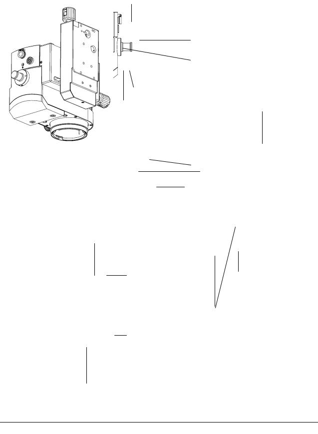
Overview optics carrier M525
Handgrip interface
M525 only: Iris reset
Drive illumination diaphragm (M525: Iris override)
LED WD lock indication |
|
WD lock button |
A/B slide |
Service & CAN res
CAN interface
Fiber optics interface
Dovetail interface
Manual drive zoom
Interface for protective glass
Laser interface
Manual drive WD
Display WD (M520/M525)

Service manual M500 N, M520, M525 |
|
Description |
Doc Code 10 665 751 |
1-3 |
08/2007 Gahe |
Electrical accessories
-All Leica handand footswitches fit to the control unit M500 N / M520 (restriction for 16 function switch – it is handled as a 12 function switch only)
-CAN handle
-DI C500
-Autofocus device
-Fluorescence devices (available for some stand systems only)
Optical/mechanical accessories
-All optical equipment with dovetail interface fit to the optics carrier. Refer to appropriate stand user manual for allowed loads and configurations
-Interface for protective glass 10 446 058
-Interface for universal Laser adapter 10 448 079 (M520 & M525)
-Interface for universal Laser adapter 10 446 615 (M500 N)
-Sterilisable knobs
-Interface for right handgrip
-Interface for fiber optic

Description |
1-4 |
Service manual M500 N, M520, M525 |
08/2007 Gahe |
Doc Code 10 665 751 |
Current configurations Leica M525 (state 08/2007)
10448237 M525 optics carrier (with A/B-slide)
10448238 M525 optics carrier (no A/B slide)
M525 F40
M525
C40/CT40
10448169 control unit
M525 MC1
M525 MS3
M525 OH4
Control unit M520 not used anymore - a new controller is integrated in OH4 system
10448068 control unit
10448144 control unit
10448236 OH4 stand system

Service manual M500 N, M520, M525 |
|
Description |
Doc Code 10 665 751 |
1-5 |
08/2007 Gahe |
Product history Leica M500N - M520 - M525
|
Date / event |
Description: |
Remark |
|
|
|
|
|
|
|
1997 / Launch M500 N |
10 446 481 M500 N optics carrier |
For stand systems OHS1, MS1, |
|
|
|
10 446 489 control unit |
MC1 |
|
|
|
|
|
|
|
02/2001 / product change in optics |
10 446 757 M500 N optics carrier |
New emergency drive for zoom |
|
|
carrier |
replaces 10 446 481 |
|
|
|
|
|
|
|
|
|
10 446 757 M500 N optics carrier |
Additional for MS2 stand system |
|
|
07/2001 / Launch with MS2 |
10 446 489 control unit |
|
|
|
|
|
|
|
|
|
10 711851 control unit for OH3 |
Additional for OH3 stand system |
|
|
11/2002 / Launch with OH3 |
10 448 019 M500 N optics carrier |
|
|
|
(without A/B slide) |
|
|
|
|
|
|
|
|
|
|
|
|
|
|
04/2003 / Launch with MS3 |
10 446 757 M500 N optics carrier |
Additional for MS3 stand system |
|
|
|
10 446 489 control unit |
|
|
|
|
|
|
|
|
10/2003 / Product change in optics |
10 448 029 M520 optics carrier |
New illumination unit and new |
|
|
carrier: New M520 optics carrier |
replaces 10 446 757 for MS2, MS3, |
multifoc objective : More light |
|
|
|
OHS1; |
30%, increased working distance |
|
|
|
10 448 035 M520 optics carrier |
from 407 to 470mm, display for |
|
|
|
(without A/B slide) for OH3 |
working distance, improved |
|
|
|
replaces 10 448 019; |
illumination optics – lead free |
|
|
|
|
glass. |
|
|
|
|
Zoom unit : new diaphragm (10 712 |
|
|
|
Upgrade kit was available: |
255) for better depth of field - |
|
|
|
10 712 316, upgrade kit M500 N to |
reduced diameter to 12mm. |
|
|
|
M520 optics carrier; description 10 |
New Lemo plug instead fixed CAN |
|
|
|
665 687; |
cable – external cable required. |
|
|
|
(10 446 757 to 10 448 070; |
|
|
|
|
10 448 019 to 10448 071) |
For stand systems OH3, OHS1, |
|
|
|
|
MS3, MS2, MS1, MC1 |
|
|
|
|
|
|
|
07/2004 / Launch M520 F40 |
10 448 029 M520 optics carrier for |
Control unit without power supply |
|
|
|
F40, 10 448 068 control unit for F40 |
and with new holder |
|
|
|
|
|
|
|
03/2005 Product change of control |
10 448 144 control unit replaces |
All stand systems from 03/2005 on |
|
|
unit: removed power supply |
10 446 489 |
can provide 24V; |
|
|
|
|
|
|
|
09/2005 Product launch M520 C40 |
10 448 029 M520 optics carrier and |
Control unit compatible, but with |
|
|
and CT40 |
new control unit 10 448 169 for C40 |
new holder |
|
|
|
and CT40 |
|
|
|
|
|
|
|
|
07/2006 Product change in M520 |
10 448 029 M520 optics carrier and |
Paint on zoom lenses as a |
|
|
optics carrier |
10 448 035 M520 optics carrier |
diaphragm |
|
|
|
with new zoom unit |
|
|
|
|
|
|
|
|
|
|
|
|

Description |
1-6 |
Service manual M500 N, M520, M525 |
08/2007 Gahe |
Doc Code 10 665 751 |
09/2006 Product change to M525 |
10 448 237 M525 optics carrier |
New illumination unit, additional |
optics carrier |
replaces 10 448 029 for MC1, F40, |
AutoIris function, new motor |
|
MS3, C40, CT40 |
controller, removed illumination |
|
10 448 238 M525 optics carrier |
zoom. |
|
(without A/B slide) replaces |
|
|
10448 035 for OH4 |
For stand systems OH4, MS3, MC1, |
|
|
F40, C40, CT40 |
|
Upgrade kit available for limited |
|
|
time: |
|
|
10 714 461 Upgrade kit M520 to |
|
|
M525; description 10 665 743 |
|
|
(10 448 029 to 10 448 246; |
|
|
10 448 035 to 10 448 247) |
|
|
|
|
Service manual M500 N, M520, M525 |
|
Description |
Doc Code 10 665 751 |
1-7 |
08/2007 Gahe |
Electrical description
General
The optics carrier is a high performance operating microscope with adjustable working height and integrated zoom, with M525 also an integrated autoIris. The zoomand the focus functions, for M525 also the Iris functions, are microprocessor controlled in order to give the user the maximum comfort. The electronics in the optics-carrier consists of only one board, with the microprocessor, memory, motorcontrollers and interfaces on it.
A control unit is needed to store the settings, to read hand/footswitches and to control the opticscarrier, manage CAN bus activities and to display the status/settings. It consists of one controller board, called control module, a LCD module and a switch panel. Former control units contain a power supply as well.
Overview of system: |
|
|
|
|
|
|
|
|
|
|
CAN-Bus |
|
|
*Possible options on |
Optics-carrier |
|
|
|
|
|
|
|
|
|
|
||
CAN bus: |
Zoom |
|
P2 |
|
|
|
|
|
P4 |
|
P7 |
Option* |
|
- |
CAN handle |
Iris |
P8 |
|
|
|
|
|
P1 |
CAN-Res. |
|||
- |
DI C500 |
|
P5 |
|
||
Multifoc |
|
P3 |
Service |
|||
- |
Autofocus |
|
|
|
|
|
|
P6 |
P9 |
P10 |
CAN-Bus |
||
- |
Swing carrier |
|
MF off |
Iris control |
|
|
- |
Fluorescence |
|
|
|||
|
|
|
|
|
||
|
|
|
|
Iris function (P8, P9, P10): only in M525 |
||
|
|
Control unit |
|
|
|
|
|
|
|
|
|
|
|
|
|
|
|
|
|
|
|
|
|
|
|
|
|
|
|
|
|
|
|
|
|
|
|
|
|
|
|
|
|
|
|
|
|
|
|
|
|
|
|
|
|
|
|
|
|
|
|
|
|
|
|
|
|
|
|
|
|
|
|
|
|
|
|
|
|
|
|
|
|
|
|
|
|
|
|
|
|
|
|
|
|
|
|
|
|
|
|
|
|
|
|
|
|
|
|
|
|
|
|
|
|
|
|
|
|
P7 |
|
J8 |
|
J9 |
|
J5 |
J6 |
|
|
|
|
|
|
|
|
|
|
|
|
|
|
|
|
|
|
|
|
|
|
|
RS-232 |
Add. |
|
|
|
|
|
|
CAN |
|
||||||
Service |
Funktion |
|
|
|
|
|
|
|
|
|
|||||
CAN-Bus
CAN CAN
Hand/Footswitch |
External. CAN |
modul |
CAN |
Leica Stand |
|
+24V |
DC |
max 240VAC |
|
AC

Description |
1-8 |
Service manual M500 N, M520, M525 |
08/2007 Gahe |
Doc Code 10 665 751 |
CAN bus
CAN-bus principle
The CAN-bus (Controller Area Network) is a bi-directional, two-wire bus. It is used to handle the communication between the control unit, the optics-carrier, the stand and other CAN devices. The CAN-bus uses a protocol which largely suppresses transmission errors.
The CAN bus in the M500 N/M520/M525 system is operated in the configuration “standard – CAN”.
Data transfer
The bus is looped through each of the controllers. Data is transferred serially, bit by bit, with differential signals. The data transfer is rated at with 50kBit/s.
The data can be exchanged between each of the controllers. A data transfer consists of:
•Start bit,
•Identification, enabling the priority to be determined,
•The data itself, and
•CRC (Cyclic Redundancy Check).
Each controller recognizes the data related to its task. If a controller wants to send data, it has to wait until the bus is free. The feature of setting the priority of commands is not applied in the M500 N/M520/M525 system; all commands have the same priority.
Command interpretation by control unit
The control unit reads CAN commands from CAN handles and from other CAN members. It interprets the received commands and releases appropriate commands to the CAN bus. The concerning CAN device will then release a required action.
Safety concept - brake watch dog
The control unit must periodically (100ms) send a brake state message. If no periodic brake state message is received by the connected stand/brake controller, all brakes will lock.
Terminating impedance
In control unit: the end of the CAN-bus is terminated with an impedance of 120Ω. The controller detects if it is at the end of the bus or if another device is connected (CAN cable is coded: Pin 4 is bridged to pin 8 in the connector housing).
In optics carrier: the controller of the optics carrier is always terminated by 120Ω; other devices, connected to the bus at the optics carrier are not terminated.
Service manual M500 N, M520, M525 |
|
Description |
Doc Code 10 665 751 |
1-9 |
08/2007 Gahe |
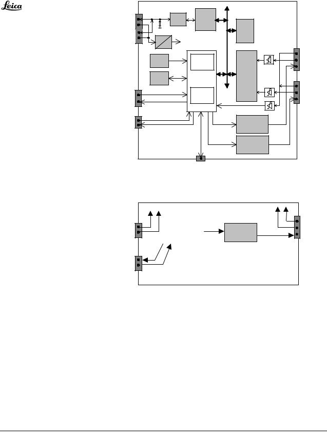
Optics carrier
Blockdiagram motorcontroller M500 N, M520
P2 |
|
|
CAN- |
CAN- |
|
|
|
|
|
|
|
||
CAN |
|
|
Controller |
|
|
|
|
|
Trans. |
|
|
||
120E |
82527 |
EPROM |
|
|||
|
|
|
|
|
|
|
CAN-Res. |
|
|
|
|
128Kx8 |
|
24V |
|
|
|
|
|
|
P3 |
5V |
5V |
|
|
P4 |
|
|
|
|
|
|
||
|
|
|
|
|
|
|
|
|
|
|
On-chip |
|
Zoom |
|
Reset |
|
|
RAM |
|
|
|
|
|
|
|
||
|
|
|
|
1kx8 |
MEM3200 |
|
|
|
|
|
Prozessor |
|
|
|
EEPROM |
|
Universal |
P5 |
||
|
|
H8/532 |
||||
|
|
|
|
|
Counter |
|
P6 |
|
|
|
On-chip- |
|
Multifoc |
|
|
|
|
|
||
MF off |
|
|
|
Peripherals, |
|
|
|
|
|
|
|
||
|
|
|
Watchdog |
|
|
|
|
|
|
|
|
|
|
|
SCI |
|
|
|
P7 |
|
|
+24V |
|
Option |
PWM |
Zoom- |
||
|
||||
|
|
Motor Driver |
||
|
PWM |
Multifoc- +24V |
||
|
|
Motor Driver |
||
|
P1 Service |
|
motcontr.ds4 |
|
|
|
|
||
Addition for motorcontroller M525:
|
|
|
P8 |
PWM |
Iris |
+24V |
Iris |
|
|
|
|
|
Motor Driver |
|
|
P10
CAN
P9
Iris control
Powering
The optics-carrier is powered via the CAN-bus cable with +24VDC. Power consumption is appr.
50mA in wait state,
150mA when one motor is running;
500mA when both motors, focus and zoom are blocked.
A DC/DC converter on the motorcontroller delivers +5V for logic supply. The +24VDC is measured on the controller board with the microprocessor analog input. It can be asked in the diagnostic menu of the control unit.

Description |
1-10 |
Service manual M500 N, M520, M525 |
08/2007 Gahe |
Doc Code 10 665 751 |
Processor
A watch-dog is integrated in the H8-processor. It observes the running of the main program. Diagnosis LED’s might help with trouble shooting, refer to chapter 4 – fault finding / diagnosis LED’s.
The PWM outputs are driven with the optimum frequency of 20kHz (above the noise-limit, below magnetization problems).
Motor driver
The zoom- , focus and Iris motors are powered with a +24V PWM-signal. A one-chip controller receives enable-, directionand the puls-rate-information from the processor and drives the motors accordingly. All motors have an encoder mounted directly on the motor axis. The encoder pulses are received by a counter, where the A/B-signals (direction) are decoded and the actual position transferred further to the processor. A current limitation for the motors becomes active for current > 0,3A.
Range
The initializing of the microscope sets the lower limit to 1000 encoder-pulses. The actual upper limit is determine with counting the encoder-pulses (constants are stored for these values; deviations of the displayed values are possible due to mechanical tolerances).
F ocus 2 07m m |
U P |
|
|
D O W N |
Focus 4 07m m or 470mm (M520, M525) |
||||||
|
|
||||||||||
Zoo m O U T |
D O W N |
|
|
UP |
Zoo m IN |
|
Zoom: 28500 |
||||
|
|
||||||||||
|
|
|
|
|
|
|
|
|
|
|
|
|
|
|
|
|
|
|
|
|
|
|
|
|
|
|
|
|
|
|
|
|
|
|
|
800 1000 |
|
|
|
|
u p p e r lim it |
||||||
|
|
|
|
|
Focus: 23800 |
||||||
|
|
|
|
|
|||||||
w orking range
ra ng e .ds 4
RS232
A serial interface for service purposes is available. It is directly wired to the Optics-carrier processor - and has therefore other signal level for TxD than RS232 standard.
Recognition of optics carrier type
Since the increase of the working distance from 407 to 470mm (M500 N to M520) a recognition of the optics carrier type is required. A bridge on P6 (pin1-pin4) is installed in optics carrier M520 and M525. A status command, requested from control unit at system start , delivers the information if the bridge is installed or not.
Additional functionality on motorcontroller for M525
The AutoIrsis function in the M525 required an additional motor and a redesign of the motorcontroller. All existing functions were taken over (backwards compatible) and additional circuits for Iris motor drive and Iris control were integrated. The movement of the Iris motor is completely handled by the motorcontroller, no direct access via the CAN bus is possible.
Software history
Software |
Release date |
HW motorcontroller |
Compatibility |
Remark |
version |
|
|
|
|
1.4 |
02/98 |
10 661 250 |
M500 N |
|
2.3 |
04/99 |
-“- |
M500 N |
|
2.4 |
05/01 |
-“- |
M500 N, M520 |
|
4.4 |
xx/06 |
10 714 356 |
M500 N, M520, M525 |
|
Software compatibility in respect of control unit see chapter inspection / step 2.13.
Service manual M500 N, M520, M525 |
|
Description |
Doc Code 10 665 751 |
1-11 |
08/2007 Gahe |
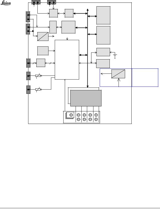
Control unit
Blockdiagram
Hand-/Footswitch 1 and 2 |
|
|
|
|||
|
|
J5 |
J6 |
|
|
|
J2 |
5V |
|
5V |
|
|
|
|
|
RS232 |
|
RAM |
|
|
CAN- |
|
|
DUART |
|
||
|
|
256kByte |
|
|||
|
|
|
|
|
||
Bus |
|
|
|
|
|
|
CAN- |
|
|
CAN- |
CAN- |
|
|
|
|
Controller |
|
|
||
Bus |
|
|
Trans. |
82527 |
|
|
|
|
|
Flash- |
|
||
J3 |
|
24V |
|
|
|
|
|
5V |
40MHz |
EPROM |
|
||
|
|
5V |
256KByte |
|
||
|
|
|
|
|
||
|
|
|
|
|
|
|
|
|
|
|
CLK2 |
|
|
|
|
Watchdog |
Processor |
Power-off |
|
|
|
|
Timer |
|
|
Timer |
"Gold"- |
|
|
|
|
|
||
P7 |
|
|
|
386EX CPU, |
|
capacitor |
Service, |
2 |
|
2 |
|
|
|
RS232 |
PLD Glue Logic, |
EEPROM |
|
|||
Download |
|
Bus Transceivers |
4 kByte |
|
||
|
|
|
||||
J8 |
|
|
|
|
+24V |
DC |
Relay |
|
|
|
|
||
|
|
|
J10 |
|
AC |
|
contact |
|
|
|
|
||
|
|
|
|
|
||
J9 |
|
|
|
J11 |
max 230V AC |
|
|
|
|
|
|
||
|
|
|
|
|
|
|
Relay |
|
|
|
LCD - Graphic Controller |
|
|
contact |
|
|
|
LCD - Display |
|
|
|
|
|
|
|
|
|
|
|
|
|
240 x 128 Dots |
|
|
|
|
|
|
with VF-backlight |
|
|
Function |
keys |
steuerge.ds4
Power supply removed since 03/2005
Powering
Control units before 03/2005 had a power inlet for 230VAC ad the built-in power supply could feed the system with +24VDC. This was required in stand systems having no own power supply like the MC1.
Since 03/2005 all stand systems have their own power supply. So the power supply was removed from control unit, now it is supplied via the CAN bus cable with 24VDC.
Processor
An Intel 386EX Processor is used. It is clocked with 20MHz. The memory consists of 256kByte RAM, 256kByte FlashEPROM and 4kByte EEPROM. The software can be updated/downloaded through the RS232 service-interface.
A watch-dog is integrated, it observes the running of the main program. Diagnosis LED’s might help with trouble shooting, refer to chapter 4 – fault finding / diagnosis LED’s.

Description |
1-12 |
Service manual M500 N, M520, M525 |
08/2007 Gahe |
Doc Code 10 665 751 |
Display / Keyboard
The communication with the user is done with help of an high-contrast display and a keyboard with nine keys. The display is a LCD Matrix (240x128 dots) with integrated Graphic controller and backlight.
Can-bus
The CAN-bus has two go-through-input/outputs with two identical parallel connectors.
Hand/Footswitch
There are two RS232 interface-connectors available for all available hand / footswitches. They are wired to the DUART-interface and are clocked with 4800 Baud. The control unit periodically (60ms) sends a request to the connected footswitch. It sends back a status code (2 Byte), indicating which key is pressed/not pressed.
Service interface
A double RS232 interface is provided for service purposes. They are both wired directly to the Processor (RXD0/TXD0, RXD1/TXD1) The connector P7 is used for both of them. COM1 (RXD0/TXD0) is programmed for a service-terminal, for example for downloading new software version into the Flash-EPROM.
Additional function
There are two relay-contacts on the control unit connector panel for additional functions. The maximum permissible loading for one contact is 1 A/24 V DC. The relay-contacts can be programmed to switchor toggle mode.
Software history
Software |
Release date |
HW control module |
Compatibility |
Remark |
version |
|
|
|
|
1.4 |
02/98 |
10 661 330 |
M500 N |
|
1.54 |
01/00 |
-“- |
M500 N |
|
1.76 |
04/02 |
-“- |
M500 N |
Supports Can handles, DI C500 |
1.81 |
|
-“- |
M500 N |
Supports OH3 |
1.84 |
|
-“- |
M500 N |
Supports MS3, CAN handle can |
|
|
|
|
be configured separate |
1.87 |
|
-“- |
M500 N, M520, M525 |
Supports M520, M525 |
Software compatibility in respect of optics carrier see chapter inspection / step 2.13.

Service manual M500 N, M520, M525 |
|
Description |
Doc Code 10 665 751 |
1-13 |
08/2007 Gahe |
Technical data
Optics carrier M525 |
|
Stock n° |
10448237 M525 optics carrier |
|
10448238 M525 optics carrier OH4 |
Zoom |
6:1 zoom, motorized |
Magnification |
Total magnification with 10x eyepiece 1,2 x to 12,8 |
Working distance |
207-470 mm, variable through motorized multi-focal lens, continuously adjustable; |
|
manually adjustable by emergency knob |
Display |
Analog display of working distance |
Field of view (diameter) |
16,5mm to 180 mm with 10x eyepiece |
Objective |
Multi-focal lens 207-470 mm variable working distance |
Illumination |
Continually adjustable illumination field diameter with gauss-shaped light distribution |
AutoIrisTM |
Built-in automatic zoom-synchronized illumination filed diameter with manual override and |
|
reset feature |
Outlet interface |
Dovetail ring |
Control unit M500 N/M520 |
|
Stock n° |
10448169 (M525 C40/CT40) |
|
10448068 (M525 F40) |
|
10448144 (MC1, MS3) |
Display |
LCD display |
Adjustment of |
Speed for zoom and focus, brightness and backlight intensity of display, WD and zoom |
Interfaces |
RS232 for service |
|
2x RS232 for foot/handswitch |
|
2x additional function (programmable relay contact) |
CAN port |
Two CAN-ports, 24V max 50W |

Description |
1-14 |
Service manual M500 N, M520, M525 |
08/2007 Gahe |
Doc Code 10 665 751 |

Service manual Leica M500 N, M520, M525 |
2-I |
Wiring |
Doc Code 10 665 751 |
07/2007 Gahe |
2. Wiring and locations Leica M500 N, M520, M525
Table of content
Chapter |
Page |
Optics carrier |
2-1 |
Control unit |
2-4 |
Overview of connectors |
2-6 |
Wiring diagrams |
2-8 |
Wiring diagram M525 719072 |
2-9 |
Wiring diagram M500 N / M520 707276 |
2-11 |

Wiring |
2-II |
Service manual M500 N, M520, M525 |
07/2007 Gahe |
Doc Code 10 665 751 |
Service manual M500 N, M520, M525 |
|
Wiring |
Doc Code 10 665 751 |
2-1 |
07/2007 Gahe |
Wiring and locations Leica M500 N, M520, M525
Optics carrier
Zoom/multifoc motor controller 10714356

Wiring |
2-2 |
Service manual M500 N, M520, M525 |
07/2007 Gahe |
Doc Code 10 665 751 |
Zoom/multifoc motor controller 10661250 (M500 N/M520 only)
Bridge for M520/M525 only;
Removed when used in M500 N
Switch board
J6 |
View from |
|
wiring side: |
||
|

Service manual M500 N, M520, M525 |
|
Wiring |
Doc Code 10 665 751 |
2-3 |
07/2007 Gahe |
Iris switch assembly
Wiring |
2-4 |
Service manual M500 N, M520, M525 |
07/2007 Gahe |
Doc Code 10 665 751 |
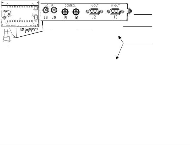
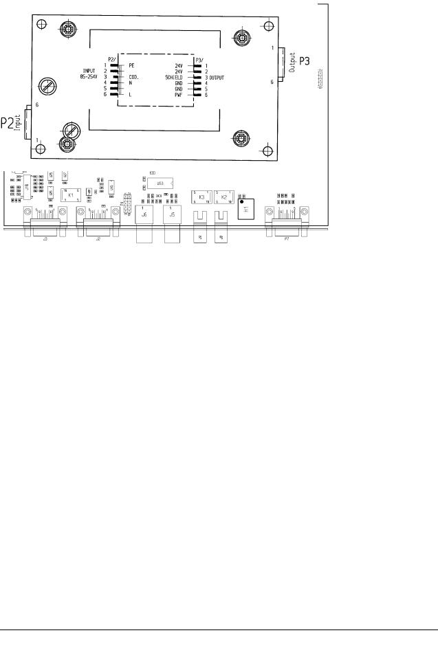
Control unit
Control module
Power supply (only in control units till March 2005)
Service manual M500 N, M520, M525 |
|
Wiring |
Doc Code 10 665 751 |
2-5 |
07/2007 Gahe |
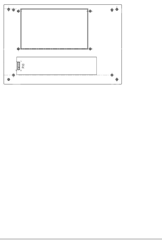
LCD module
P11
J12
Switch panel

|
Wiring |
|
|
2-6 |
Service manual M500 N, M520, M525 |
||
|
07/2007 Gahe |
|
|
|
Doc Code 10 665 751 |
||
|
Overview of connectors |
|
|
|
|||
|
|
|
|
|
|
|
|
|
Connector |
|
Page |
|
Module / connecting to |
|
|
|
|
|
|
|
|
|
|
|
Optics Carrier |
|
|
|
|
|
|
|
|
|
|
|
|
|
|
|
P1 |
|
2-1, 2-2 |
|
Motor controller / service port |
|
|
|
|
|
|
|
|
|
|
|
P2 |
|
2-1, 2-2 |
|
Motor controller / CAN |
|
|
|
|
|
|
|
|
|
|
|
P3 |
|
2-1, 2-2 |
|
Motor controller / CAN res. |
|
|
|
|
|
|
|
|
|
|
|
P4 |
|
2-1, 2-2 |
|
Motor controller / zoom motor |
|
|
|
|
|
|
|
|
|
|
|
P5 |
|
2-1, 2-2 |
|
Motor controller / focus motor |
|
|
|
|
|
|
|
|
|
|
|
P6 |
|
2-1, 2-2 |
|
Motor controller / switch board |
|
|
|
|
|
|
|
|
|
|
|
J6 |
|
2-2 |
|
Switch board |
|
|
|
|
|
|
|
|
|
|
|
P7 |
|
2-1, 2-2 |
|
Motor controller / Res. |
|
|
|
|
|
|
|
|
|
|
|
J7 |
|
- |
|
Optics carrier / Service/CAN res. (Lemo with cap) |
|
|
|
|
|
|
|
|
|
|
|
P8 |
|
2-1 |
|
Motor controller / Iris motor |
|
|
|
|
|
|
|
|
|
|
|
P9 |
|
2-1 |
|
Motor controller / Iris switch assembly |
|
|
|
|
|
|
|
|
|
|
|
J9 |
|
2-3 |
|
Iris switch assembly |
|
|
|
|
|
|
|
|
|
|
|
P10 |
|
2-1 |
|
Motor controller / CAN (to stand system) |
|
|
|
|
|
|
|
|
|
|
|
Control unit |
|
|
|
|
|
|
|
|
|
|
|
|
|
|
|
P1 |
|
2-4 |
|
Control module / test port (not used) |
|
|
|
|
|
|
|
|
|
|
|
P2 |
|
2-4 |
|
Power supply / input power |
|
|
|
|
|
|
|
|
|
|
|
J2 |
|
2-4 |
|
Control module / CAN1 |
|
|
|
|
|
|
|
|
|
|
|
P3 |
|
2-4 |
|
Power supply / output power |
|
|
|
|
|
|
|
|
|
|
|
J3 |
|
2-4 |
|
Control module / CAN2 |
|
|
|
|
|
|
|
|
|
|
|
P4 |
|
2-4 |
|
Control module / not used |
|
|
|
|
|
|
|
|
|
|
|
J5 |
|
2-4 |
|
Control module / remote 1 |
|
|
|
|
|
|
|
|
|
|
|
J6 |
|
2-4 |
|
Control module / remote 2 |
|
|
|
|
|
|
|
|
|
|
|
P7 |
|
2-4 |
|
Control module / service RS232 |
|
|
|
|
|
|
|
|
|
|
|
J8 |
|
2-4 |
|
Control module / add. function 1 |
|
|
|
|
|
|
|
|
|
|
|
J9 |
|
2-4 |
|
Control module / add. function 2 |
|
|
|
|
|
|
|
|
|
|
|
J10 |
|
2-4 |
|
Control module / switch panel |
|
|
|
|
|
|
|
|
|
|
|
P10 |
|
2-5 |
|
Switch panel / control module |
|
|
|
|
|
|
|
|
|
|
|
P11 |
|
2-5 |
|
LCD module / control module |
|
|
|
|
|
|
|
|
|
|
|
J11 |
|
2-4 |
|
Control module / LCD module |
|
|
|
|
|
|
|
|
|
|
|
|
|
|
|
|
|
|

|
Service manual M500 N, M520, M525 |
Wiring |
||
|
Doc Code 10 665 751 |
2-7 |
07/2007 Gahe |
|
|
|
|
|
|
|
P12 |
2-4 |
Control module / LCD module backlight |
|
|
|
|
|
|
|
J12 |
2-5 |
LCD module /control module |
|
|
|
|
|
|
|
P13 |
2-4 |
Control module / input from power module |
|
|
|
|
|
|

Wiring |
2-8 |
Service manual M500 N, M520, M525 |
07/2007 Gahe |
Doc Code 10 665 751 |
Wiring diagrams in A3 format
Wiring diagram M525 10719072 on page 2-9
Wiring diagram M500 N/M520: 707276 A on page 2-11
 Loading...