


DMI3000 B
Leica DMI3000B,
DMI4000B, DMI6000B
Instructions · Bedienungsanleitung · Mode d’emploi

Published August 2010 by:
Herausgegeben August 2010 von:
Edité en août 2010 par :
Leica Microsystems CMS GmbH
Ernst-Leitz-Straße 17-37
D-35578 Wetzlar (Germany)
Responsible for contents:
Verantwortlich für den Inhalt:
Responsable du contenu rédactionnel :
Bernard Kleine
(Marketing CMS, Life Science Research Microscopy, Product
Management)
(Marketing CMS, Life Science Research Microscopy, Produkt-
management)
(Marketing CMS, Life Science Research Microscopy,
chef de produit)
Dietmar Gnass
(R&D Manager)
In case of questions, please contact the hotline:
Bei Fragen wenden Sie sich bitte an die Hotline:
Pour toute question, contacter notre service d’assistance
téléphonique :
Phone: +49 (0) 64 41 - 29 42 53
Fax: +49 (0) 64 41 - 29 22 55
E-Mail: MQM-Hotline@leica-microsystems.com

3
Leica DMI3000B,
DMI4000B, DMI6000B
Instructions

4
Copyrights
Copyrights
All rights to this documentation are held by Lei-
ca Microsystems CMS GmbH. Reproduction of
text or illustrations (in whole or in part) by print,
photocopy, microfi lm or other method (including
electronic systems) is not allowed without ex-
press written permission from Leica Microsys-
tems CMS GmbH.
The term „Windows“ may appear in the following
text without further identifi cation. It is, however,
a registered trademark of Microsoft Corpora-
tion. The names of companies and products used
herein may be trademarks of their respective
owners.
The instructions contained in the following docu-
mentation refl ect state-of-the-art technology
standards. We have compiled the texts and illus-
trations as accurately as possible. Nevertheless,
no liability of any kind may be assumed for the
accuracy of this manual’s contents. Still, we are
always grateful for comments and suggestions
regarding potential mistakes within this docu-
mentation.
The information in this manual is subject to modi-
fi cation at any time and without notifi cation.

5
Contents
6.10 Installation and Replacement of the
transmitted Light Lamps:
107 or 107/2 Lamp Housing........................ 45
6.11 Installing the Lamp Housing Mount
and Mirror Housing) ................................... 46
6.12 Installation and Replacement of
Incident Light Lamps .................................. 48
6.13 Equipping the Incident Light
Turret Disk .................................................... 52
6.14 Inserting the Front Module Slider ............ 55
6.15 Installation of the Polarizer
and Analyzer................................................ 55
6.16 Optional Accessories................................. 57
6.17 Connection to the Electronics Box .......... 58
6.18 Connection to the Computer ..................... 59
6.19 Connection to the Power Supply ............. 59
7. Start-up ........................................................ 60
7.1 Functional Principle .................................. 60
7.2 Switching on the Microscope .................. 64
7.3 The LeicaDisplay ........................................ 65
7.4 The Function Buttons on the Stand ......... 66
7.5 The SmartMove
Remote Control Module ............................ 69
7.6 Illumination .................................................. 69
7.6.1 Transmitted light .............................. 69
7.6.2 Incident Light - Fluorescence ........ 73
7.7 Checking Phase Contrast Rings ............... 74
7.8 Checking modulation contrast
slit diaphragms............................................ 77
7.9 Setting the Motorized Polarizer ............... 77
7.10 Adjusting the Light Sources ..................... 78
Contents
1. Important Notes about this Manual ........ 7
2. Intended Purpose of the Microscope ..... 8
3. Safety Notes ................................................ 9
3.1 General Safety Notes ................................ 9
3.2 Electrical Safety.......................................... 10
3.3 Safety Instructions
for Handling the Light Sources ................ 12
3.4 Notes on handling laser devices ............. 12
3.5 Safety Instructions
for Handling Acids and Bases .................. 12
3.6 Disposal........................................................ 13
4. Overview of the Leica DMI Series .......... 14
5. Unpacking the Microscope ..................... 27
6. Assembling the Microscope .................... 30
6.1 Assembly Tools ........................................... 30
6.2 Installation of the Transmitted Light
Illumination Carrier (TL) ............................. 31
6.3 Installation of the DIC Module
and DIC Objective Prisms ......................... 32
6.4 Installation of Specimen Stages .............. 33
6.5 Installation of Condensers ........................ 38
6.6 Installation of Eyepieces ........................... 43
6.7 Installation of Objectives .......................... 43
6.8 Installation of Filters
in the Illumination Arm............................... 44
6.9 Installing the transmitted Light
Lamp Housing ............................................. 44

6
Contents
8. Operation ..................................................... 81
8.1 Switching on................................................ 81
8.2 Contrast Methods ....................................... 83
8.2.1 Bright Field (TL) ................................ 83
8.2.2 Phase Contrast (TL) ....................... 85
8.2.3 Dark Field (TL) .................................. 86
8.2.4 Polarization (TL) ............................... 87
8.2.5 Differential
Interference Contrast (TL) ............. 88
8.2.6 Integrated Phase Contrast (TL) ..... 89
8.2.7 Integrated
Modulation Contrast (TL) ................ 90
8.3 Fluorescence............................................... 91
8.4 Combination Methods ............................... 93
8.5 Focusing ....................................................... 94
8.6 Tubes ............................................................ 96
8.7 Port selection ............................................. 96
8.8 Eyepieces..................................................... 97
8.9 Objectives .................................................... 98
8.10 Stages and Object Displacement ............ 101
8.11 Magnifi cation Changer .............................. 102
8.12 Light sources ............................................... 103
8.13 Aperture and Field Diaphragm ................ 104
9. Troubleshooting .......................................... 105
10. Care of the Microscope ............................ 109
10.1 Dust Cover ................................................... 109
10.2 Cleaning ....................................................... 109
10.3 Handling Acids and Bases ........................ 110
11. Major Consumable
and Replacement Parts ............................. 111
12. Dimensions.................................................. 112
13. Abbreviations and Pictograms ................ 113
14. Index ............................................................ 115
15. EU Declaration of Conformity .................. 117
7
1. Important Notes about this Manual
(1.2)
→ p. 20
!
*
Numbers in parentheses, such as „(1.2)“, corre-
spond to illustrations (in the example, Figure 1,
Item 2).
Numbers with pointer arrows (for example
→ p. 20), point to a certain page of this manual.
Caution!
Special safety instructions within this manual
are indicated with the triangle symbol shown
here, and have a gray background.
Caution! The microscope and accessories can
be damaged when operated incorrectly.
Notes on the disposal of the microscope, ac-
cessories and consumable materials.
Explanatory note.
Item not contained in all confi gurations.
Text symbols, pictograms and their meanings:
Caution!
This operating manual is an essential com-
ponent of the microscope, and must be read
carefully before the microscope is assem-
bled, put into operation or used.
1. Important Notes about this Manual
This operating manual contains important in-
structions and information for the operational
safety and maintenance of the microscope and
accessories. It must therefore be kept safely for
future reference.
A separate manual is available on CD-ROM cov-
ering the operation of the Leica Application Suite
(LAS).
8
2. Intended Purpose of the Microscope
2. Intended Purpose of the Microscope
The Leica DMI Series microscopes covered in
this manual are designed for biological, routine,
and research applications. This includes the ex-
amination of samples taken from the human body
in order to provide information on physiological
or pathological states or congenital abnormali-
ties; to determine the safety and compatibility
with potential recipients; or to monitor therapeu-
tic measures.
The Leica DMI Series is an additional develop-
ment of Leica’s proven inverted research mi-
croscopes, designed for cellular and tissue
examination, micromanipulation and microinjec-
tion techniques, microdissection, and confocal
microscopy. The Leica DMI Series is suitable
for universal deployment. All contrast methods
such as dark fi eld, bright fi eld, phase contrast,
DIC, fl uorescence, and modulation contrast are
integral to the microscope and can be adapted
or changed quickly and easily. Variable illumi-
nation and imaging beam paths, as well as HCS
optics, modular accessories, and a comprehen-
sive range of peripherals complement the Leica
Microsystems inverted research stand.
The above-named microscope series complies
with the Council Directive 98/79/EEC concern-
ing in vitro diagnostics. They also conform to the
Council Directives 73/23/EEC concerning electri-
cal apparatus and 89/336 /EEC concerning elec-
tromagnetic compatibility for use in an industrial
environment.
Caution!
The manufacturer assumes no liability for
damage caused by, or any risks arising from,
using the microscopes for purposes other
than those for which they are intended or not
using them within the specifi cations of Leica
Microsystems CMS GmbH.
In such cases the declaration of conformity
shall cease to be valid.
Caution!
These (IVD) devices are not intended for use
in the patient environment defi ned by DIN
VDE 0100-710. Neither are they intended for
combining with medical instruments accord-
ing to EN 60601-1. If a microscope is electri-
cally connected to a medical instrument
according to EN 60601-1, the requirements
defi ned in EN 60601-1-1 shall apply.
8
9
3. Safety Notes
3. Safety Notes
3.1 General Safety Notes
This safety class 1 device is constructed and
tested in accordance with
EN 61010-2-101:2002,
EN 61010-1:2001,
IEC 61010-1:2001,
Safety regulations for electrical measuring, con-
trol, and laboratory devices.
Caution!
In order to maintain this condition and to en-
sure safe operation, the user must follow the
instructions and warnings contained in this
operating manual.
Caution!
The devices and accessories described in
this operating manual have been tested for
safety and potential hazards.
The responsible Leica affi liate or the main
plant in Wetzlar must be consulted whenever
the device is altered, modifi ed or used in con-
junction with non-Leica components that are
outside of the scope of this manual.
Unauthorized alterations to the device or
noncompliant use shall void all rights to any
warranty claims!
9

10
3. Safety Notes
3.2 Electrical Safety
General Specifi cations
Leica CTR4000, CTR5000, CTR5500, CTR6000,
CTR6500, CTR7000, CTR6500 HS, CTR7000 HS
Electronics Boxes
For indoor use only.
Supply voltage:
Frequency:
Power input:
Fuses:
Ambient temperature:
Relative humidity:
Over voltage category:
Pollution degree:
Microscope
For indoor use only.
Supply voltage:
Frequency:
Power input:
Fuses:
Ambient temperature:
Relative humidity:
Over voltage category:
Pollution degree:
90–250 V~
50–60 Hz
max. 290 VA
T6.3 A
(IEC 60127-2/3)
15–35°C
max. 80% to 30°C
II
2
90–250 V~
50–60 Hz
see CTR4000–7000
see CTR4000–7000
15–35°C
max. 80% to 30°C
II
2
ebq 100 supply unit*
For indoor use only.
Supply voltage:
Frequency:
Power input:
Fuses:
Ambient temperature:
Relative humidity:
Over voltage category:
Pollution degree:
(see enclosed manual)
Leica EL6000*
For indoor use only.
Supply voltage:
Frequency:
Power input:
Fuses:
Ambient temperature:
Relative humidity:
Overvoltage category:
Pollution degree:
(see enclosed manual)
100–240 VAC
50–60 Hz
max. 200 VA
5x20, 2.5 A, slow,
breaking capacity H
0°–40°C
10–90%
non-condensing
II
2
90–250 V~
50–60 Hz
See CTR4000–7000 HS
See CTR4000–7000 HS
15–35°C
max. 80% to 30°C
II
2
11
3. Safety Notes
Caution!
The microscope’s electrical accessory com-
ponents are not protected against water. Wa-
ter can cause electric shock.
Caution!
Protect the microscope from excessive tem-
perature fl uctuations. Such fl uctuations can
lead to the accumulation of condensation,
which can damage the electrical and optical
components.
Ambient temperature: 15–35°C.
Caution!
Before exchanging the fuses or lamps, be ab-
solutely certain to switch off the main power
switch and remove the power cable.
Caution!
Power plugs may only be plugged into an out-
let equipped with a grounding contact.
Do not interfere with the grounding function
by using an extension cord without a ground
wire. Any interruption of the ground wire in-
side or outside of the device, or release of
the ground wire connection, can cause the
device to become hazardous. Intentional
ground interruption is not permitted!
Caution!
Peripheral devices with their own or sepa-
rate power supplies that are connected to
the microscope can have the same protec-
tive conductor potential by connecting them
to the ground screw on the back of the Leica
CTR4000, CTR6000, CTR6500 and CTR7000
electronics boxes. For connections without
a ground connector, Leica Service must be
consulted.
Caution!
Never use any fuses as replacements other
than those of the types and the current rat-
ings listed here. Using patched fuses or
bridging the fuse holder is not permitted. The
use of incorrect fuses may result in a fi re haz-
ard.

12
3. Safety Notes
3.3 Safety Instructions
for Handling the Light Sources
Caution!
Light sources pose a potential irradiation risk
(glare, UV-radiation, IR-radiation). Therefore,
lamps have to be operated in closed hous-
ings.
Never look directly into the beam path (blind-
ing hazard).
Connect the light guide to the microscope
fi rst to prevent exposing the user to the high-
energy light output of the Leica EL6000 com-
pact light source.
Never look directly into the light emitted by
the light guide.
3.4 Notes on handling laser devices
The microscope is not suitable for coupling laser
devices into the camera ports (refer to Chapter
4), as this creates a danger to the user from laser
radiation.
For use of the microscope with lasers, Leica
Microsystems offers special microscopes with
additional safety devices.
For further information, please contact your au-
thorized Leica Microsystems representative.
Caution!
Follow safety instructions for immersion oil!
3.5 Safety Instructions
for Handling Acids and Bases
For examinations using acids or other aggressive
chemicals, particular caution must be taken.
Caution!
Be absolutely certain to prevent coming into
contact with these chemicals.

13
3. Safety Notes
3.6 Disposal
To dispose of the product at the end of its service
life, please contact Leica Service or Sales.
Please observe national laws and regulations,
such as those implementing and enforcing the
WEEE EU Directive.
Note!
Like other electronic devices, the micro-
scope, its accessories and consumable ma-
terials must not be disposed of as regular
household waste.

14
4. Overview of the Instruments
4.1 Specifi cations
4. Overview of the Leica DMI Series
Contrast Methods
Transmitted Light Axis
Leica DMI Series
• transmitted light (TL): BF, DF, PH, DIC, Pol
• intermediate pupil:
IMC (integrated modulation contrast)
IPH (Integrated phase contrast)
• incident light (IL): Fluo
Leica DMI4000 B and DMI6000 B
• combination (TL/IL): Fluo/DIC, Fluo/PH
Leica DMI Series
• Manual and coded transmitted light illumination arm with inte-
grated mechanical tilt mechanism to provide adequate space for
specimens and micromanipulators, integrated fi eld dia phragm,
fi lter magazine for 2 replaceable fi lters, condenser quick-chang-
er
•
Illumination Manager (aperture diaphragm, fi eld diaphragm, light in-
tensity)
• manual shutter
• lamp housing mount for interchangeable lamp housings.
• with integrated cable channel
Leica DMI4000 B and Leica DMI6000 B
• Motorized or manual/coded transmitted light illumination arm
with integrated mechanical tilt mechanism to provide adequate
space for specimens and micromanipulators, integrated motor-
ized fi eld diaphragm, motorized fi lter magazine for 2 replace able
fi lters, condenser quick-changer
• with integrated cable channel
• automatic Illumination Manager
(aperture, fi eld diaphragm, intensity, process switching)
• manual or motorized shutter
• lamp housing mount for interchangeable lamp housings.
• automatic, electronic condenser identifi cation

15
4. Overview of the Instruments
Leica DMI3000 B
• manual shutter
• lamp housing mount for up to 3 interchangeable light sources
• manual 5-place fi lter turret
• Fluorescence Intensity Manager (FIM)
(reduction of incident illumination intensity)
Leica DMI4000 B and Leica DMI6000 B
• automatic Illumination Manager
(aperture, fi eld diaphragm*, intensity, process switching)
• motorized shutter (switching speed < 50 ms)
• lamp housing mount for up to 3 interchangeable light sources
• motorized 6-place fi lter turret
• Fluorescence Intensity Manager (FIM)
(reduction of incident illumination intensity)
• Optional: Interface for structured illumination
• Leica DMI6000 B:
mechanical booster lens for central boosting of
fl uorescence or uniform distribution
• motorized Excitation Manager* to monitor fl uorescence emission
when using double and triple fi lter cubes
• ultra fast fi lter wheel for 3 excitation wavelengths
(switching speed < 50 ms)
Leica DMI Series
• ergonomic with or without camera port at left
• 2 switching positions: 100%VIS and 50%VIS / 50%CAM or
• 2 switching positions: 100%VIS and 0%VIS / 100%CAM
• optional Bertrand lens
• eye spacing adjustment
• height and angle adjustment (30° - 45°)
Leica DMI4000 B and Leica DMI6000 B
• motorized
• 3 switching positions
(choice of magnifi cations: 1x; 1.5x; 1.6x or 2.0x)
• effective on all camera ports and eyepieces
or Leica DMI Series
• manual
• 2 switching positions
(choice of magnifi cations: 1x; 1.5x; 1.6x or 2.0x)
• effective on tube port and eyepieces
Incident Light Axis
Tube
Magnifi cation Changer
* not in combination with structured Illumination

16
4. Overview of the Instruments
Leica DMI6000 B
• motorized and coded
• 6x for objectives with M25 thread and 45 mm parfocal distance
• for DIC: motorized or manual/coded Wollaston prism carousel
• anti-vibration locking
Leica DMI4000 B
• manual and coded
• 6x for objectives with M25 thread and 45 mm parfocal distance
• for DIC: motorized or manual/coded Wollaston prism carousel
Leica DMI3000 B
• manual
• 6x for objectives with M25 thread and 45 mm parfocal distance
• for DIC: manual Wollaston prism carousel
Leica DMI Series
Fixed regular stages
• Ceramic-coated stage plate (248 mm x 204 mm)
• heating stage plate (3°C above room temperature to 60°C)
(248 x 212 mm)
• temperature-controlled stage plate (0°C to 60°C)
(248 mm x 212 mm)
• fi xed micromanipulation stages
• ceramic-coated stage plate (248 mm x 204/122 mm)
• heated stage plate (from 3°C above room temperature
to 60°C) (248 mm x 204/122 mm)
• temperature-controlled stage plate (0°C to 60°C)
(248 mm x 204/122 mm)
• regular manual and motorized 3-plate cross-stage
• positioning range: 83 mm x 127 mm
• 20 optional inserts (standard, heating, cooling) for a variety
of applications, size of inserts:160 mm x 110 mm
(compatible with scanning stages)
• narrow manual and motorized micromanipulation
3-plate cross-stage
• positioning range: 40 mm x 40 mm
• 3 optional inserts for a variety of applications
• Scanning stage 120 x 100 (motors on bottom)
• 1 mm, 2 mm, 4 mm spindle pitch
(higher resolution vs. higher speed)
• 20 optional inserts (standard, heating, cooling) for a variety
of applications, size of inserts:160 mm x 110 mm
Objective Turret
Stages

17
4. Overview of the Instruments
Condensers
Z Focus
Observation Ports
Leica DMI4000 B and Leica DMI6000 B
(identical for Leica DMI3000 B, but manual)
• motorized and coded or manual and coded
• motorized or manual aperture diaphragm
• contrast methods: BF, DF, PH, DIC, Pol, IMC, IPH
• automatic method switching
• condenser turret with 7 positions for contrast methods
• 2 condenser housings (S1-S28 and S40,S70)
• condenser heads: S1/1.4 oil, S1/0.9 dry, S23/0.53, S28/0.55
• condenser heads can be swung out
• condenser S40/S70 with additional lens for low magnifi cations
• all condensers suitable for magnifi cations from 1.25x to 100x
• with or without motorized or manual polarizer
• with or without motorized or coded Wollaston prism disk
Leica DMI6000 B
• motorized and coded
• 9 mm travel (1 mm below, 8 mm above the stage)
• maximum travel speed: 5 mm/s
• 5 focus steps: 0.05 µm; 0.1 µm; 0.7 µm; 1.5 µm; 5.0 µm
• electronic focus repositioning
• automatic lowering prior to objective change
• electronic parfocality
• Optional: Adaptive Focus Control (AFC)
Leica DMI3000 B and Leica DMI4000 B
• manual
• 9 mm travel (1 mm below, 8 mm above the stage)
Leica DMI6000 B
• motorized and coded
• left side ports (100%, 80% or 50% transmission)
• left side port dichroic splitting at 680 nm
• right side ports (100%, 80% or 50% transmission)
• bottom port
optional
• top port with 2 switching positions
• 100% to eyepieces
• 50% to eyepieces/ 50% to port
Leica DMI4000 B
left side port, manual (100% or 80% transmission)

18
4. Overview of the Instruments
Observation Ports
Controls
Electronics Box
Leica DMI3000 B
(a manual side port is a standard feature of the Leica DMI3000 B stand)
• manual
• left side port (80% or 100% transmission)
Leica DMI4000 B and Leica DMI6000 B
• 7 fi xed control buttons for illumination and apertures
• 7 variable function buttons behind the focus controls
• 3 fi xed control buttons for focus stops (Leica DMI6000 B only)
• 2 focus hand wheels
• 7 buttons for fl uorescence cubes and shutters
• 4 buttons for magnifi cation changer and ports
• SmartMove: ergonomic remote control module for x,y,z control
and four additional variable function buttons
• STP6000
Leica DMI3000 B
• 2 focus hand wheels
• 1 illumination hand wheel
• 2 turning knobs for fi eld diaphragm and FIM adjustment
• 1 On/Off switch
• separate control unit for all motorized and electronic elements of
the microscope such as:
For CTR6500 (HS)/CTR7000 (HS) only
• scanning stages
For CTR6000 only
• motorized 3-plate cross-stages
For CTR6000/7000
• objective turret
• focus
• ports
• magnifi cation changer
• fl uorescence
• condenser
• power supply for SmartMove
For all CTR boxes
with
• power supply for 100W halogen lamps

19
4. Overview of the Instruments
Leica DMI4000 B and Leica DMI6000 B
• 2 x RS232C
• 2 x USB
• 4 x external/internal peripherals
• CTR boxes
• SmartMove
• STP6000
Leica DMI4000 B and Leica DMI6000 B
• Leica Application Suite (LAS) for Windows
TM
with plug-ins for:
• microscope and camera confi guration
• microscope and camera control
• image acquisition
Interfaces
Software Tools
20
4. Overview of the Instruments
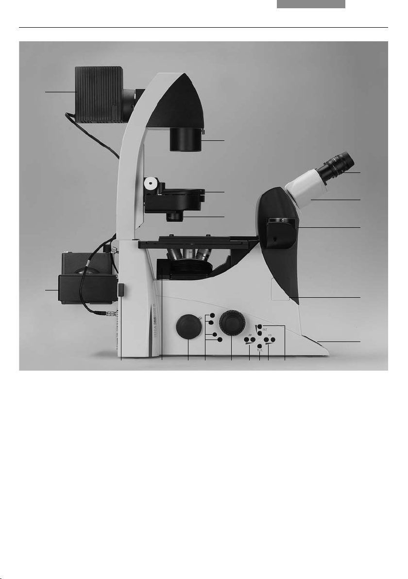
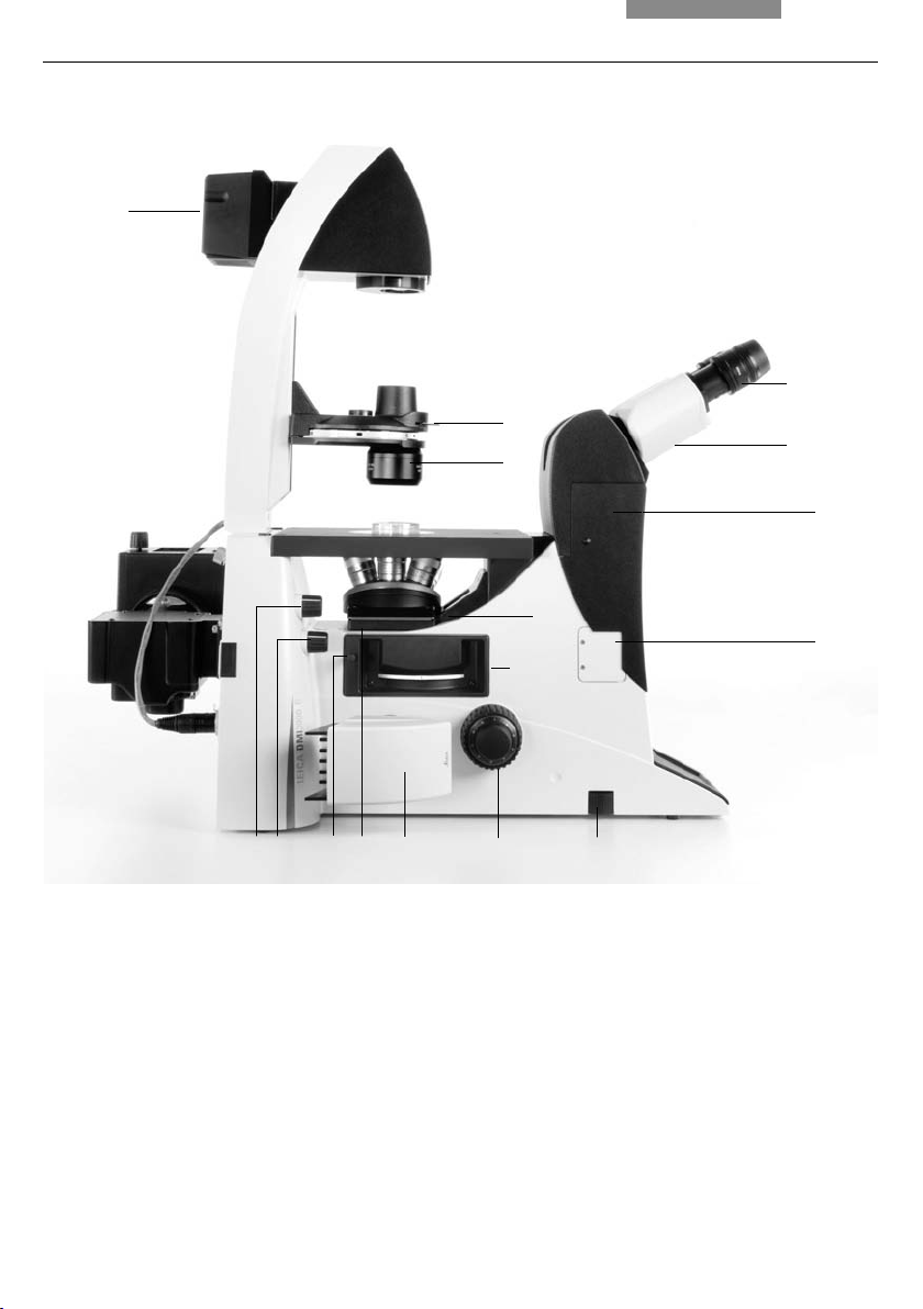
Fig. 1 Left side, Leica DMI4000 B and DMI6000 B
1 Eyepiece
2 Eyepiece tube
3 Top port
4 Intermediate pupil interface
5 LeicaScreen
6 Light intensity
7 Field diaphragm
8 TL/IL switching
9 Aperture diaphragm
10 Focus wheel (motorized Leica DMI6000 B,
manual (fi ne and coarse) Leica DMI4000 B)
11 Variable function buttons
12 Left side port
13 Booster lens
(Leica DMI6000 B fl uorescence microscopes only)
14 Lamp mount (fl uorescence microscopes only)
15 Condenser head
16 Condenser base
17 Field diaphragm
18 Transmitted light lamp housing
19 DIC objective prism disk
1
2
3
4
5
678910111213
14
15
17
16
18
19
21
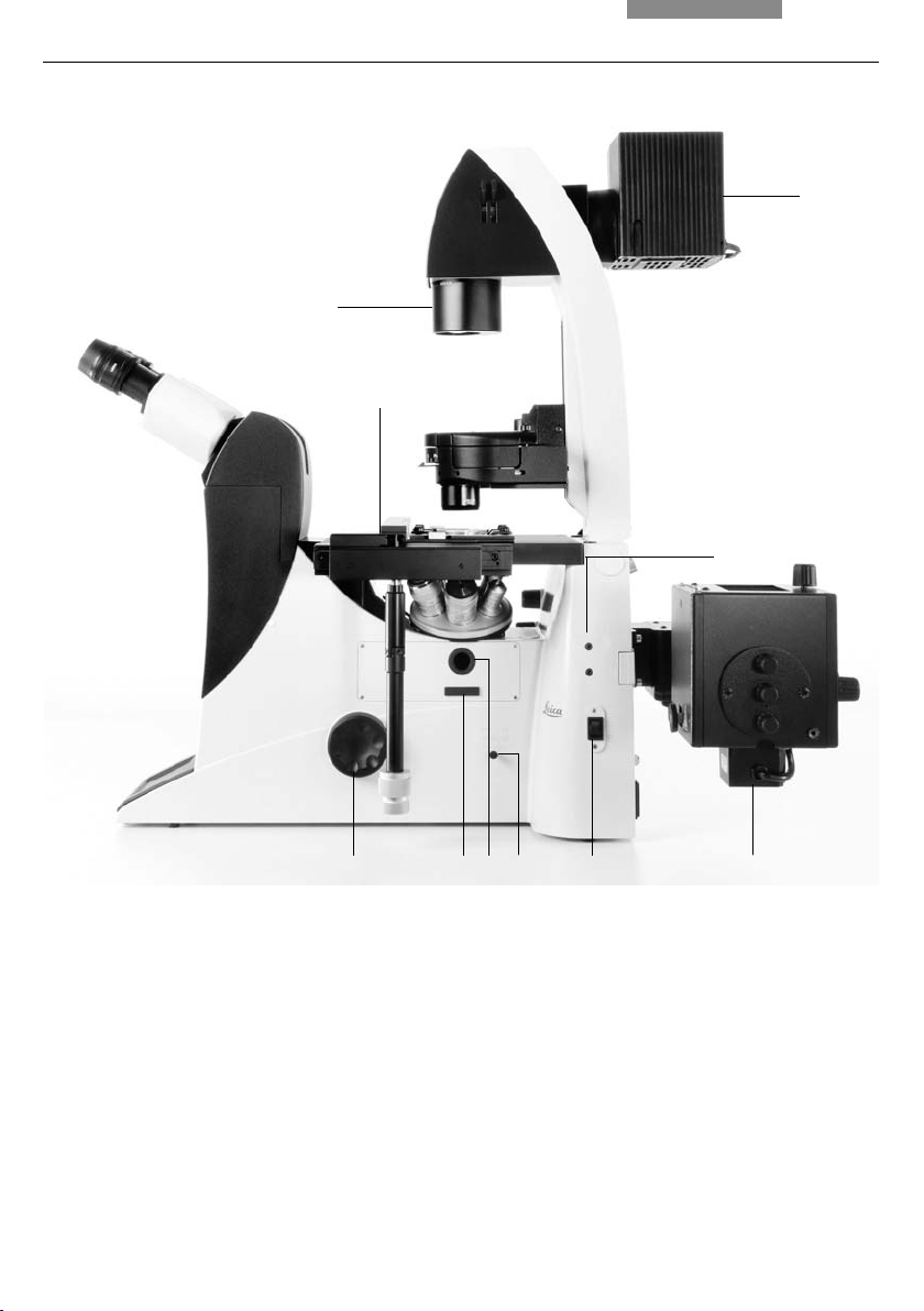
4. Overview of the Instruments
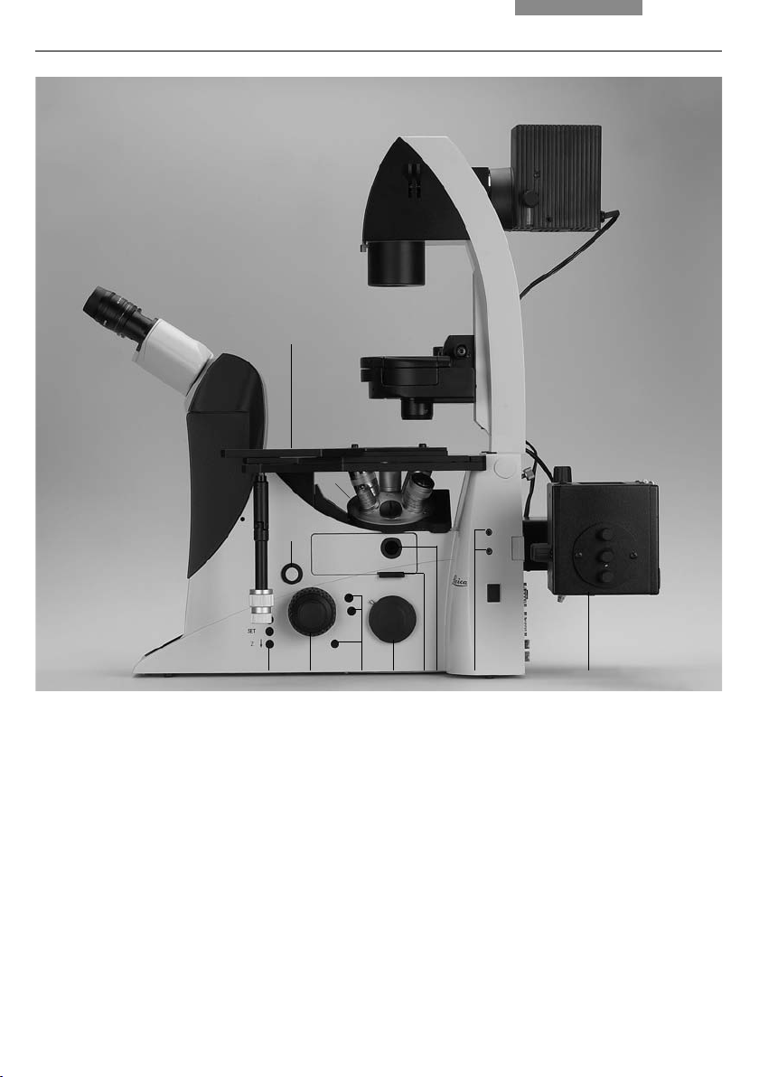
Fig. 2 R
ight side Leica DMI4000 B and DMI6000 B
1 E-Focus buttons (Leica DMI6000 B only)
2 Focus wheel (motorized Leica DMI6000 B,
manual (fi ne) Leica DMI4000 B)
3 Variable function buttons
4 Opener for drawer (fl uorescence microscopes only)
5 Drawer (fl uorescence microscopes only)
6 Right side port
7 Analyzer slot
8 Centering window (fl uorescence microscopes only)
9 Field diaphragm centering
(fl uorescence microscopes only)
10
Incident light lamp housing (fl uorescence microscopes
only)
11 Objective turret
12 Stage with attachable mechanical stage
12 3
4
5
6 78
12
9 10
11
22
4. Overview of the Instruments
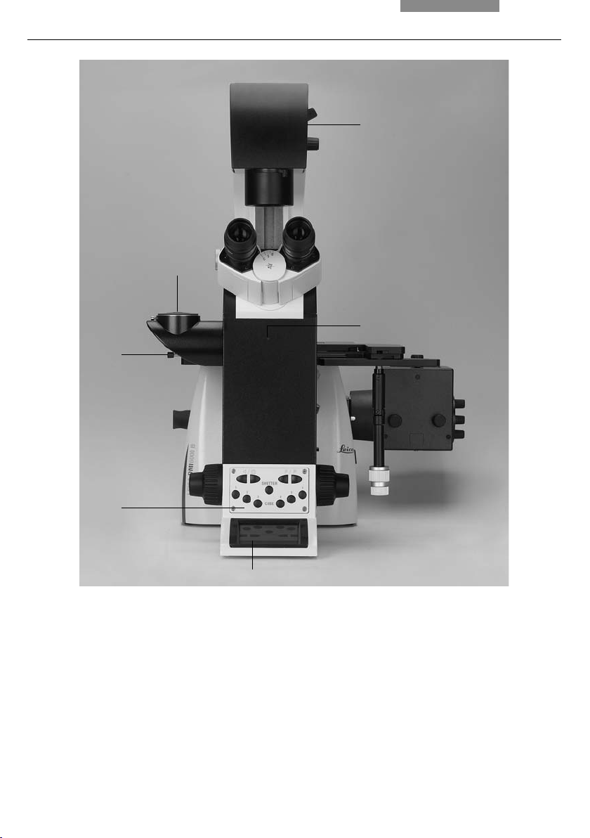
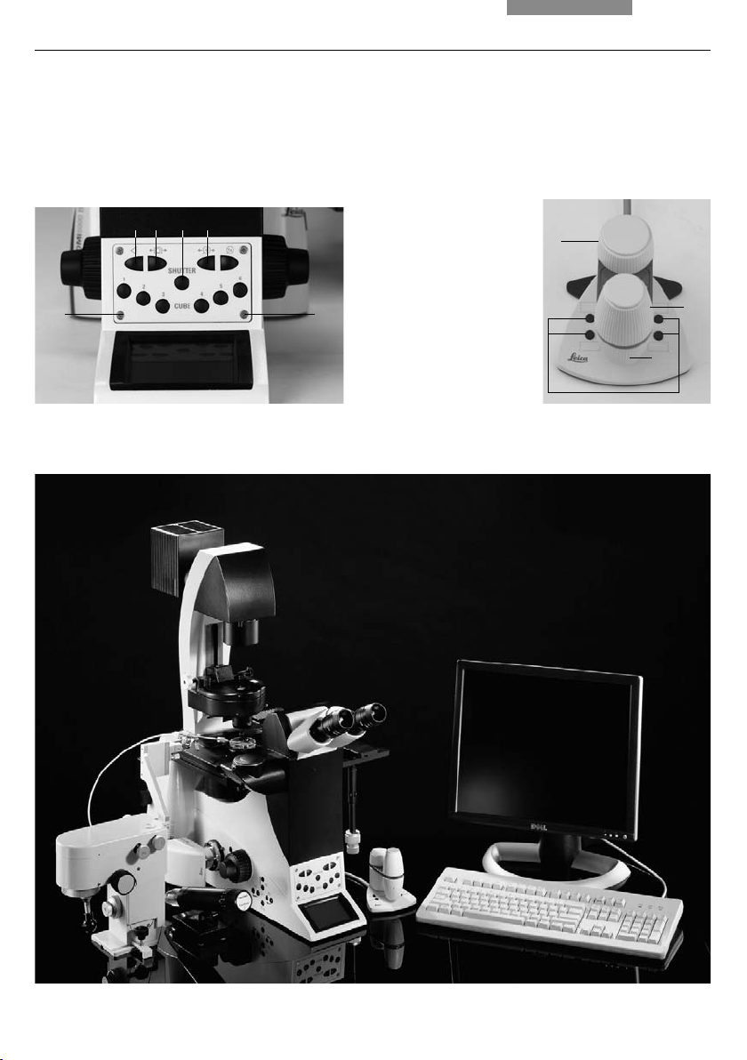
Fig. 3 Front view Leica DMI4000 B and Leica DMI6000 B
1 LeicaScreen
2 Front control panel
3 Port switching
4 Top port
5 Manual transmitted light fi lters
6 Bertrand lens centering
1
2
3
4
6
5
23
4. Overview of the Instruments
Fig. 4 General view Leica DMI4000 B and Leica DMI6000 B with SmartMove remote control module
Fig. 3b SmartMove remote control module
1 Travel in x
2 Travel in y
3 Focus
4 Variable function buttons
(pre assigned at factory)
1
2
3
4
Fig. 3a Front control panel
1 Fluorescence cube
2 Shutter
3 100% light to all eyepieces
4 Port selection
5 Magnifi cation selection
6 1x tube lens
11
2
543
24
4. Overview of the Instruments
1
2
3
4
567
14
15
16
8
12
13
91011
Fig. 5a Leica DMI3000 B left view
1 Eyepiece
2 Eyepiece tube
3 Top port
4 Intermediate pupil interface
5 Light intensity
6 Focus wheel
7 Left side port with camera
8 Objective turret
9 Filter slider
10 Adjustment FIM
11 Adjustment fi eld diaphragm
12 Drawer (fl uorescence microscopes only)
13 DIC objective prism disk
14 Condenser head
15 Condenser base
16 Integrated 30W transmitted light lamp housing
25
4. Overview of the Instruments
1
2
10
35
8
6
9
7
4
Fig. 5b
Leica DMI3000 B right view
1 Focus wheel
2 Analyzer slot
3 Centering window (fl uorescence microscopes only)
4 Port switching
5 On/Off switch
6 Incident light lamp housing (fl uorescence microscopes only)
7 Field diaphragm centering
8 Transmitted light lamp housing
9 Field diaphragm
10 Stage with attachable mechanical stage
26
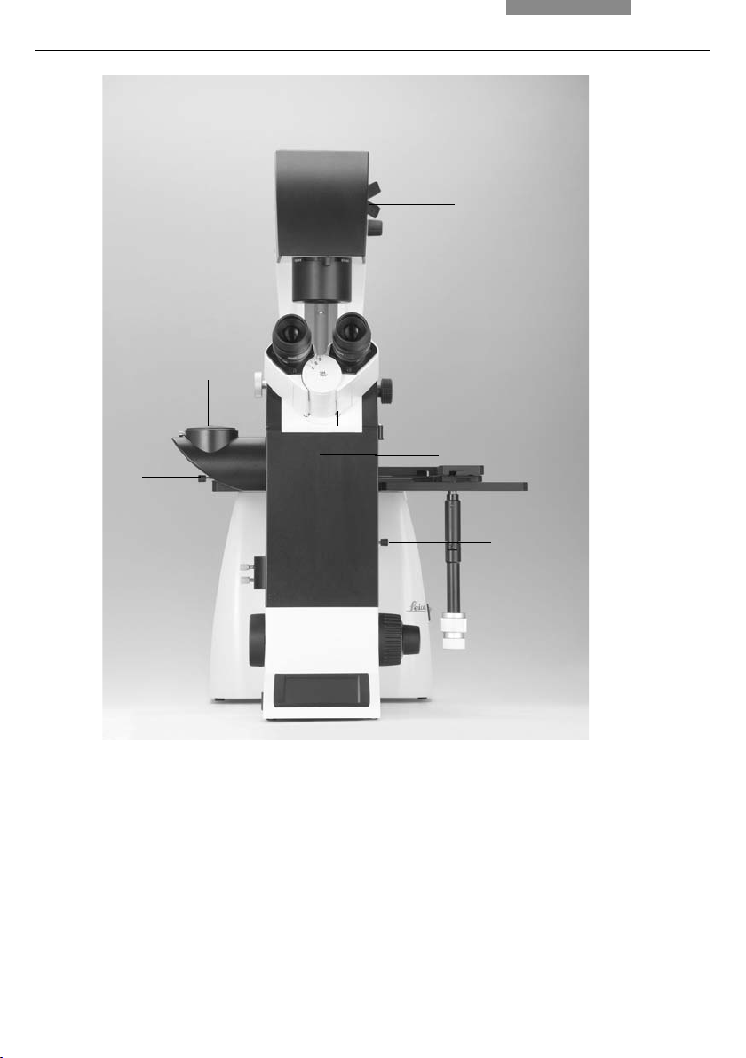
4. Overview of the Instruments
Fig. 6 Leica DMI3000 B front view
1 Port switching and Bertrand lens
2 Top port
3 Manual transmitted light fi lters
4 Bertrand lens centering
5 Manual magnifi cation changer
1
2
4
3
5

27
5. Unpacking the Microscope
The microscope is delivered in several pack-
ages.
The stand package contains the following com-
ponents:
• Stand with integrated incident light axis,
objective turret, and tube
• Illumination arm
• Specimen stage
• CD with Leica Application Suite (LAS) software
package
• Instructions and list of microscope presets
(identifi cation sheet)
The system package contains the microscope‘s
accessories:
• Eyepieces
• Objectives
• Condenser
• Lamp housings with accessories
• Assembly tools
• Additional accessories such as fi lter cubes,
etc. depending on feature set
The Leica CTR4000, CTR5000, CTR5500, CTR6000,
CTR6500, CTR7000, CTR6500 HS, CTR7000 HS
electronics box, the SmartMove, STP6000 remote
control module,
movable stages, stage acces-
sories,
the external ebq 100 supply unit and the
compact light source Leica EL6000 are provided
in separate packages.
5. Unpacking the Microscope
28
5. Unpacking the Microscope
Please carefully compare the contents of the de-
livery to the packing slip, delivery note or invoice.
We strongly recommend storing a copy of these
documents with the manual to ensure that you
have information on the date and scope of deliv-
ery handy for subsequent orders or service work.
Please ensure that no small parts remain in the
packing material. Parts of the packing material
are marked by symbols to simplify recycling.
First, carefully remove all components from the
transportation and packaging materials.
Caution!
Do not put the instrument into operation in the
event of visible damage to the components or
packing material.
Note:
If at all possible, avoid touching the lens surfaces
of the objectives. If fi ngerprints do appear on the
glass surfaces, remove them with a soft leather
or linen cloth. Even small traces of fi nger perspi-
ration can damage the surfaces in a short time.
See the chapter „Care of the Microscope“ → p.
109, for additional instructions.
Caution!
Do not connect the microscope or peripher-
als to an AC power source at this time under
any circumstances!
Installation Location
Work with the microscope should be performed
in a dust-free room, which is free of oil vapor and
other chemical vapor, as well as extreme humid-
ity. At the workplace, large temperature fl uc-
tuations, direct sunlight, and vibration should be
avoided. These may adversely affect measure-
ments and long-term observations.
Allowable ambient conditions
Temperature 15–35°C
Relative humidity maximum 80% up to 30°C
Microscopes in warm and warm-damp climatic
zones require special care in order to prevent the
build up of fungus.
See the chapter „Care of the Microscope“
→ p. 109, for additional instructions.
Caution!
Electrical components must be placed at
least 10 cm from the wall and away from
fl ammable substances.

29
5. Unpacking the Microscope
Transport
For shipping or transporting the microscope and
its accessory components, the original packag-
ing should be used.
As a precaution to prevent damage from vibra-
tions, the following components should be disas-
sembled and packaged separately:
• Unscrew the objectives.
• Remove the eyepieces.
• Remove the condenser.
• Remove the specimen stage.
• Remove the transmitted-light arm.
• Remove the lamp housings.
• Remove the lamp housing mount.
• Disassemble the burner of 106 z lamp housing.
• Remove the fi lter cube.
• Remove all moving or loose parts.

30
6. Assembly
6. Assembling the Microscope
The microscope components* are logically as-
sembled in this order:
• Transmitted light illumination carrier
• DIC module and DIC objective prisms
• Condenser with condenser head
• Eyepieces
• Objectives
• Transmitted light lamps
• Lamp housing mount (mirror housings)
• Incident light lamps
• Assembly of incident light turret disk
• Specimen stage
• Polarizer and analyzer
The order may be vary when using
climate cham-
bers or other systems and optical accessories.
In this case, read Chapter
„6.16 Optional Accessories“ → p. 57.
6.1 Assembly Tools
If possible, the microscope should be assembled
and set up with the assistance of Leica sales or
service personnel.
A small number of universal screwdrivers which
are included in the scope of delivery are required
for assembly (Fig. 7).
Fig. 7 Assembly tools
1 Phillips screwdriver*
2
3 mm Allen key
3 1.5 mm centering key*
4 2 mm centering key*
5 3 mm hex key*
6 2.5 mm hex key* (short type)
7 2.5 mm hex key*
1
2
5
6
2
3
4
7
* depending on scope of delivery
 Loading...