


 Loading...
LEICA SPRINTER
User Manual
Version 1.2
English

|
|
SPRINTER 100/100M/200/200M |
2 |
|
|
|
|
|
|
Introduction |
|
|
|
|
|
|
|
|
|
Purchase |
Congratulations on the purchase of a new Leica Geosystems Digital Level. |
|
||
Product |
SPRINTER 100/100M/200/200M is the new high quality electronic digital level produced |
|||
|
|
by Leica Geosystems. It is designed to make levelling easier and quicker in any construc- |
||
|
|
tion site. It employs techniques that electronically read the special bar-coded staff and the |
||
|
|
gathered data is displayed on the screen almost instantly. Its innovative technology makes |
||
|
|
the daily surveying jobs easier. |
|
|
|
|
This manual contains important safety directions as well as instructions for setting up the |
||
|
|
|||
|
|
product and operating it. Refer to "11 Safety Directions" for further information. |
|
|
|
|
Read carefully through the User Manual before you switch on the product. |
|
|
Product |
The model and the serial number of your product are indicated on the type plate. |
|
||
identification |
Enter the model and serial number in your manual and always refer to this information |
|
||
|
|
when you need to contact your agency or Leica Geosystems authorized service work- |
|
|
|
|
shop. |
|
|
|
|
Type: |
_______________ |
|
|
|
Serial No.: |
_______________ |
|
|
|
Software-Version: |
_______________ |
|
|
|
|
|
|

Symbols |
The symbols used in this manual have the following meanings: |
||
|
Type |
Description |
|
|
|
Danger |
Indicates an imminently hazardous situation which, if not avoided, |
|
|
will result in death or serious injury. |
|
|
|
Warning |
Indicates a potentially hazardous situation or an unintended use |
|
|
which, if not avoided, could result in death or serious injury. |
|
|
|
Caution |
Indicates a potentially hazardous situation or an unintended use |
|
|
which, if not avoided, may result in minor or moderate injury and/or |
|
|
|
|
appreciable material, financial and environmental damage. |
|
) |
Important paragraphs which must be adhered to in practice as they |
|
|
enable the product to be used in a technically correct and efficient |
||
|
|
|
manner. |
|
|
|
|
Trademarks |
All trademarks are the property of their respective owners. |
||
|
|
|
|
SPRINTER 100/100M/200/200M |
3 |

|
|
SPRINTER 100/100M/200/200M |
4 |
|
|
|
|
Table of Contents |
|
||
|
|
|
|
In this manual |
Chapter |
Page |
|
|
|
|
|
|
1 |
How to Use this Manual |
5 |
|
|
|
|
|
2 |
Description of the System |
7 |
|
|
|
|
|
3 |
Measurement Preparation |
10 |
|
|
|
|
|
4 |
User Interface |
14 |
|
|
|
|
|
5 |
Operation |
32 |
|
|
|
|
|
6 |
Data and Memory Management (only SPRINTER 100M/200M) |
44 |
|
|
|
|
|
7 |
Check & Adjust |
47 |
|
|
|
|
|
8 |
Messages |
54 |
|
|
|
|
|
9 |
Settings |
59 |
|
|
|
|
|
10 |
Care and Transport |
61 |
|
|
|
|
|
11 |
Safety Directions |
63 |
|
|
|
|
|
12 |
Technical Data |
75 |
|
|
|
|
|
Index |
|
80 |
|
|
|
|

1 How to Use this Manual
)It is recommended to set-up the product while reading through this manual.
Path |
Main Menu: Data Manager\ View Data stands for this working sequence: |
|
From the Main Menu select Data Manager…. and then select View Data. |
Screen |
CONFIGURE General Menu describes the name of the screen. |
Page |
Screens can have more than one page. Units page describes a specific page of a screen. |
|
For example: ’...in CONFIGURE Units & Formats, Units page...’. |
Index |
The index is at the back of the manual. |
)Keys, fields and options on the screens which are considered as self-explanatory are not explained.
Validity of this |
This manual is valid for both SPRINTER 100/200 and SPRINTER 100M/200M. Sections |
manual |
only valid for SPRINTER 100M/200M are marked accordingly. |
How to Use this Manual |
SPRINTER 100/100M/200/200M |
5 |

How to Use this Manual |
SPRINTER 100/100M/200/200M |
6 |
Available documentation
Name of |
Description |
documentation |
|
SPRINTER |
All instructions required in order to operate the instrument at its |
100/100M/200/200M |
basic level are contained in this User Manual. Provides an over- |
User Manual |
view of the system together with technical data and safety |
|
directions. |
SPRINTER |
2 pages of short description on operating the instrument. |
100/100M/200/200M |
|
Quick-guide |
|
|
|
2 Description of the System
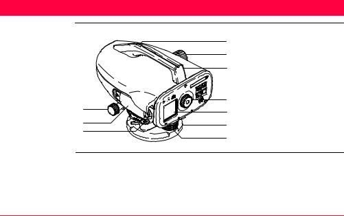
Instrument components
a
b
c
Sprinter_01
d
e
fa) Horizontal fine motion screw
b)Battery compartment
c)Circular level
d)Gunsight
g |
e) |
Focusing knob |
h |
f) |
Handle |
|
g) |
Eyepiece |
i |
h) |
LCD display |
j |
i) |
Base plate |
|
j) |
Levelling footscrew |
Description of the System |
SPRINTER 100/100M/200/200M |
7 |
Description of the System |
SPRINTER 100/100M/200/200M |
8 |
|
|
|
|
|
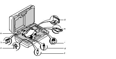
Container Contents
a) SPRINTER b) Batteries (4x) c) Allen key
d) Manual, CD-ROM e) Strap
f) Sunshade (optional)
g) Plumb adapter (optional) h) Plumb bob (optional)

Accessories |
• |
Tripod |
|
|
• |
Aluminum Staff (Region dependant) |
|
|
• |
Rain cover (Optional) |
|
|
• |
Sunshade (Optional) |
|
|
• |
Power supply |
|
|
|
• 4 AA alkaline dry - cells |
|
|
|
• 4 Rechargeable batteries and charger (Optional) |
|
|
• Data Transfer / Recording to external device |
||
|
|
• Computer cable - serial interface (Optional) |
|
|
• |
Computer software |
|
|
|
• Leica Geo Office Tools for data downloading to PC |
|
|
• |
Documentation |
|
|
|
• |
User Manual |
|
|
• |
Quick-guide |
|
|
|
|
Description of the System |
SPRINTER 100/100M/200/200M |
9 |
Measurement Preparation |
SPRINTER 100/100M/200/200M |
10 |
|
|
|
|
|
3 Measurement Preparation |
|
||
|
|
|
|
In this chapter |
Topic |
|
Page |
|
|
|
|
|
3.1 |
Battery |
10 |
|
|
|
|
|
3.2 |
Set-up instrument |
11 |
|
|
|
|
3.1Battery
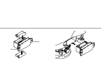
Change battery step- by-step
a
a
Sprinter_02
Sprinter_03
Step Description
1.Simultaneously depress the locking clips (a) on the battery cover and remove it.
2.Insert the 4 AA dry cells the right way round according to the positive and nega-
tive signs as indicated on the cover.
) Always replace with a complete battery set! ) • Do not use old and new batteries together.
•Do not use batteries from different manufacturers or batteries of
different types.
•For type of battery, refer to Technical Data.
3.Place the compartment back and push until a click is heard.
3.2Set-up instrument
Levelling |
Step |
Description |
|
1.Set up the tripod. Extend the legs to a suitable length and ensure that the tripod head is approximately level. Tread the tripod shoes firmly into the ground to ensure stability.
2.Mount the instrument on the tripod by screwing the tripod screw onto the base of the instrument.
Measurement Preparation |
SPRINTER 100/100M/200/200M |
11 |
Measurement Preparation |
SPRINTER 100/100M/200/200M |
12 |
Step Description
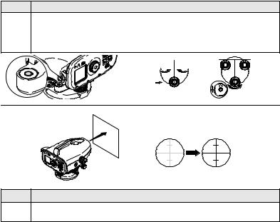
3.Use the three levelling foot screws to center the circular bubble in order to level the instrument. Turn the telescope of the instrument perpendicular to foot screws A and B. Turn foot screws A and B simultaneously in opposite direction until the bubble is in the center of the imaginary "T". Finally turn the foot screw C until the bubble is shifted to the center of the circular vial.
A B
B
 C
C
Eyepiece Adjustment
Sprinter_05
Step Description
4.Point the telescope to a uniform light surface such as a wall or a piece of paper. Turn the eyepiece until the cross hairs are sharp or distinct.
Target Image
Focusing
Power ON
)
Step Description
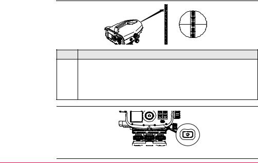
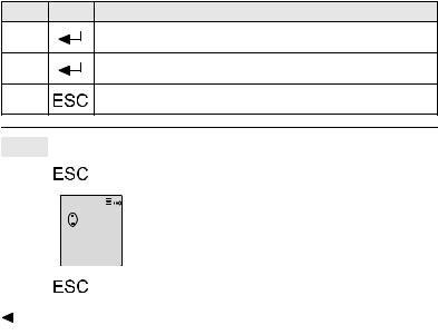
5.Use the gunsight to aim the objective lens at the staff. Turn the horizontal fine motion screw until the staff is nearly centered in the field of view and then turn the focusing knob to focus on the staff. Looking through the telescope, shift your eyes slightly up and down and if the staff and the reticle does not show any deviation or displacement against one another, then the instrument is ready for
usage. Otherwise, both steps 3 and 4 should be repeated.
) Use only SPRINTER staff produced by Leica Geosystems
ESC
Sprinter_07
The instrument is ready to measure.
Measurement Preparation |
SPRINTER 100/100M/200/200M |
13 |

User Interface |
|
SPRINTER 100/100M/200/200M |
14 |
|
|
|
|
4 User Interface |
|
|
|
|
|
|
|
In this chapter |
Topic |
|
Page |
|
|
|
|
|
4.1 |
Screen Display |
15 |
|
|
|
|
|
4.2 |
Operating Keys and Functions |
15 |
|
|
|
|
|
4.3 |
Modes |
17 |
|
|
|
|
|
4.4 |
Icons |
17 |
|
|
|
|
|
4.5 |
Menu Navigation |
18 |
|
|
|
|
|
4.6 |
Menu Setting |
19 |
|
|
|
|
|
4.7 |
Set of Characters |
22 |
|
|
|
|
|
4.7.1 |
Entering Numeric Values |
22 |
|
|
|
|
|
4.7.2 |
Entering Alphanumeric Values |
27 |
|
|
|
|
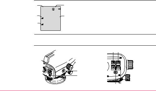
4.1Screen Display
a |
|
|
|
|
|
|
|
|
|
b |
|
|
|
MEAS |
|
|
|
|
|
|
a) |
Mode |
|||
|
|
|
|
|
|
|
|
|
|
|
||
e |
|
|
|
|
1.235m |
c |
||||||
|
|
|
: |
b) |
Icons |
|||||||
|
|
|||||||||||
d |
|
|
: |
5.68m |
|
c) |
Measurement units |
|||||
|
|
|
d) |
Distance symbol |
||||||||
|
|
|
|
|||||||||
|
|
|
||||||||||
|
|
|
|
|
|
|
|
|
|
|
e) |
Height symbol |
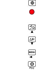
4.2Operating Keys and Functions
b
a
Sprinter_08
c |
|
f |
|
|
ESC |
Sprinter_09 |
d |
e |
User Interface |
SPRINTER 100/100M/200/200M |
15 |
User Interface |
SPRINTER 100/100M/200/200M |
16 |
|||||||
|
|
|
|
|
|
|
|
|
|
|
Pos. |
Key |
Symbol |
1st level functions |
2nd level functions |
||||
|
a) |
On/Off |
|
|
|
|
|
Power On or Off switch |
NONE |
|
|
|
|
|
|
|
|
|
|
|
b) |
MEAS |
|
|
|
|
|
Measuring trigger key for |
2nd function (Continuous |
|
|
|
|
|
|
|
|
measuring height and |
measurement) with |
|
|
|
|
|
|
|
|
distance |
prolonged key press of 2 |
|
|
|
|
|
|
|
|
|
seconds |
|
c) |
Height / |
|
|
|
|
|
Alternating between Height |
Cursor up (when in Menu |
|
|
Distance |
|
|
|
|
|
and Distance display |
mode) |
|
|
|
|
|
|
|
|
|
|
|
d) |
dH |
|
|
|
|
|
Height Difference measure- |
Cursor down (when in Menu |
|
|
|
|
|
|
|
|
ment and RL computation |
mode) |
|
|
|
|
|
|
|
|
|
|
|
e) |
MENU |
|
|
|
|
|
Activation and Selection of |
ENTER key for confirmation |
|
|
|
|
|
|
|
|
settings |
purpose (when in Menu |
|
|
|
|
|
|
|
|
|
mode) |
|
|
|
|
|
|
|
|
|
|
|
f) |
Backlight |
|
|
|
|
|
LCD backlight illumination |
ESC key for termination of |
|
|
|
|
|
|
|
|
|
program or setting (when in |
|
|
|
|
|
|
|
|
|
Menu mode) |
|
|
|
|
|
|
|
|
|
|

4.3Modes
Modes |
|
|
|
|
|
Symbol |
Mode |
||
|
|
|||
|
|
|
|
Measurement Mode |
|
|
MEAS |
|
|
|
|
|
|
|
|
|
|
|
|
|
|
|
|
MENU selection Mode |
|
|
MENU |
|
|
|
|
|
|
|
|
|
|
|
|
|
|
|
|
Adjustment Mode |
|
|
ADJ |
|
|
|
|
|
|
|
|
|
|
|
|
|
|
|
|
Tracking Mode |
|
|
TRK |
|
|
|
|
|
|
|
|
|
|
|
|
|
|
|
|
|
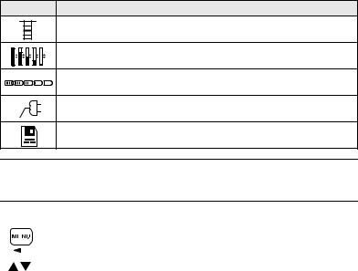
4.4Icons
Description |
Icons show the current status information of the instrument. |
|||||
|
|
|
|
|
|
|
|
Icon |
Description |
||||
|
|
|
|
|
|
LCD backlight on |
|
|
|
|
|
|
|
|
|
|
|
|
|
Staff upright measuring mode |
|
|
|
|
|
|
|
|
|
|
|
|
|
|
|
|
|
|
|
|
|
|
|
|
|
|
|
|
User Interface |
SPRINTER 100/100M/200/200M |
17 |
User Interface |
SPRINTER 100/100M/200/200M |
18 |
Icon Description
Inverted Staff measuring mode
Different levels of LCD contrast display (10% change per step)
Battery icon at various capacities (0%, 25%, 50%, 75%, 100%)
External power utilized (applicable to SPRINTER 100M/200M)
Data stored to internal memory (applicable to SPRINTER 100M/200M)
4.5Menu Navigation
Icon |
Description |
|||
|
|
|
|
To access the MENU, press MENU key. |
|
|
|
|
|
|
|
|
|
|
|
|
|
|
Press to scroll the cursor up or down. |
|
|
|
|
|
Icon Description
Press to select highlighted MENU item and submenu is displayed.
Press to select highlighted submenu item, a "Setting…" message prompted; and display return to last measurement application.
To exit from submenu, press key once will go to menu; press key again and display will return to last measuring application.
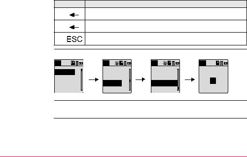
Example
Selecting BEEP to ON:
MENU |
MENU |
MENU |
MENU |
1.Input PtID
2.Input RL
3.Data Manager
4.Recording
5. Adjustment |
9.Auto Off |
BEEP |
|
6. Inverse Staff |
10.Rounding |
On |
|
7. Contrast |
11. Beep |
||
Off |
|||
8. Units |
12.Baudrate |
||
|
4.6Menu Setting
No. |
Sub Menus |
Selections |
Descriptions |
1. |
Input PtID |
|
To input user point ID (Applicable to |
|
|
|
SPRINTER 100M/200M) |
User Interface |
SPRINTER 100/100M/200/200M |
19 |
User Interface |
SPRINTER 100/100M/200/200M |
20 |
|||
|
|
|
|
|
|
|
No. |
Sub Menus |
Selections |
Descriptions |
|
|
2. |
Input Reduced |
|
Input for Benchmark value / Reference |
|
|
|
Level (RL) |
|
Reduced Level |
|
|
3. |
Data Manager |
View, |
Viewing of individual recorded data / |
|
|
|
|
Delete, |
deleting of specific measured target data |
|
|
|
|
Download |
Deleting of all measuring data |
|
|
|
|
|
Transferring of data via PC software (applicable |
|
|
|
|
|
to SPRINTER 100M/200M) |
|
|
4. |
Recording |
Memory, |
Data can be recorded in the internal memory of |
|
|
|
|
OFF, |
the instrument or externally to the external |
|
|
|
|
External |
device such as data collectors.(applicable to |
|
|
|
|
|
SPRINTER 100M/200M). If the recording is set |
|
|
|
|
|
OFF, then the captured data will not be stored. |
|
|
5. |
Adjustment |
None |
Adjustment program |
|
|
6. |
Inverse Staff |
ON = |
Setting of measurement to Inverted Staff. By |
|
|
|
|
Inverted |
default or on power on, the mode is always set |
|
|
|
|
mode |
to OFF. |
|
|
|
|
OFF = |
|
|
|
|
|
Upright |
|
|
|
|
|
mode |
|
|
|
7. |
Contrast |
10 levels of |
Optimum contrast setting for LCD display. |
|
|
|
|
selections |
Contrast is set to 50% ex factory. |
|
|
8. |
Unit |
M, INT ft, |
Display Unit setting in meters, international feet, |
|
|
|
|
US ft, Ft in |
US feet, and ft in 1/8in |
|
|
|
|
1/8in |
|
|
No. |
Sub Menus |
Selections |
Descriptions |
9. |
AutoOFF |
ON 15 min / |
Power saving function. If set to ON 15 min, the |
|
|
OFF |
instrument will switch off about 15 minutes after |
|
|
|
the last key press. |
|
|
|
In the case of OFF, the instrument will be |
|
|
|
permanently switched on |
10. |
Rounding |
Precise/ |
Setting of minimum display reading: |
|
|
Standard |
In metric: Standard = 0.001m for height and |
|
|
|
0.01m for distance. |
|
|
|
Precise = 0.0001 m for height and 0.001m for |
|
|
|
distance |
|
|
|
In Ft: Standard (Int. and US ft) = 0.01 ft and |
|
|
|
distance = 0.1 ft |
|
|
|
Precise = 0.001 ft for height and 0.01 ft for |
|
|
|
distance. |
|
|
|
In Ft in 1/8 inch: Precise & Standard = |
|
|
|
ft-inch-1/8 inch for height and distance |
11. |
Beep |
ON/OFF |
Acoustic signal trigger key ON or OFF |
12. |
RS232 (appli- |
Baudrate |
1200, 2400, 4800, 9600, 19200, 38400 |
|
cable to |
Parity |
None, Odd, Even |
|
SPRINTER |
||
|
100M/200M) |
Stop Bit |
1, 2 |
|
|
||
|
|
Data Bit |
7, 8 |
User Interface |
SPRINTER 100/100M/200/200M |
21 |
User Interface |
SPRINTER 100/100M/200/200M |
22 |
4.7Set of Characters
Reduced level (RL) Reduced level (RL) numeric input consists of 0 ~ 9, space, decimal, Ft in 1/8 inch separator, the "+" and "-" signs.
Point ID (PtID) |
Point ID (PtID) alphanumeric input consists of a ~ z, 0 ~ 9 and space. |
4.7.1Entering Numeric Values
Description |
Numeric fields can only contain numeric values, positive / negative signs, Ft in 1/8 inch |
|
separator and decimal points. Numeric fields are e.g.: reference level. |
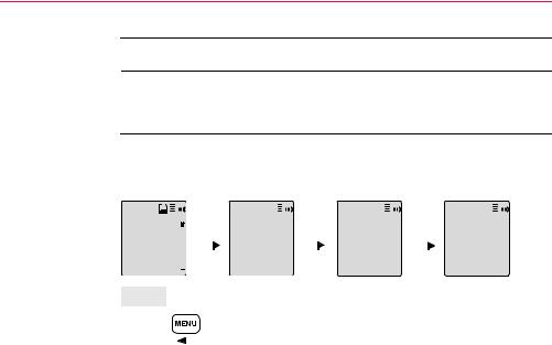
Initializing the numeric REFERENCE reduced level (RL) input:
|
MENU |
|
|
|
|
|
|
|
|
|
|
|
|
|
MENU |
|
|
|
|
|
|
|
MENU |
|
|
|
|
|
|
|
|
|
|
|
||||||
|
|
|
|
|
|
|
|
|
|
|
|
|
|
|
|
|
|
|
|
|
|
|
|
|
|
|
|
|
|
|
|
|
|
|
|
|
|
|
|
|
|
1. Input PtID |
|
|
|
|
|
|
|
|
|
Enter Ref. RL (m) |
|
|
Enter Ref. RL (m) |
RL: 100.038m |
|||||||||||||||||||||||||
|
|
|
|
|
|
|
|
|
||||||||||||||||||||||||||||||||
|
2. Input RL |
|
|
|
|
|
|
|
|
|
|
RL: |
|
|
|
|
|
|
|
|
RL: 100.03 |
|
|
|
|
|
|
|
|
|
Meas. Reference |
|||||||||
|
3. Data Manager |
|
|
|
|
|
|
|
|
8 |
|
|
|
|
|
To change RLgoto |
||||||||||||||||||||||||
|
|
|
|
|
|
|
|
|
|
|
|
|
|
|
|
|||||||||||||||||||||||||
|
4. Recording |
|
|
|
|
|
|
|
|
|
|
|
|
|
|
|
|
|
|
|
|
|
|
|
|
|
|
|
|
|
menu |
|||||||||
|
|
|
|
|
|
|
|
|
|
|
|
|
|
|
|
|
|
|
|
|
|
|
|
|
|
|
|
|
|
|
|
|
|
|
|
|||||
|
|
|
|
|
|
|
|
|
|
|
|
|
|
|
|
|
|
|
|
|
|
|
|
|
|
|
|
|
|
|
|
|
|
|
|
|
|
|
|
|
|
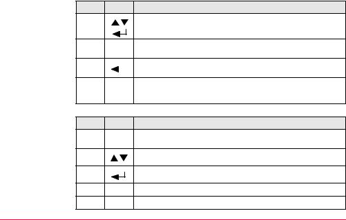
Step |
|
Key |
Description |
|
|
|
|
|
|
|
|
|
|
|
|
|
|
|
|
|
|
|
|||||||||||||||||
|
1. |
|
|
|
|
|
|
|
|
|
|
|
Press Menu key to start menu for selection. |
|
|
|
|
|
|
|||||||||||||||||||||
|
|
|
|
|
|
|
|
|
|
|
|
|
|
|
|
|
|
|
|
|
|
|
|
|
|
|
|
|
|
|
|
|
|
|
|
|
|
|
|
|
|
|
|
|
|
|
|
|
|
|
|
|
|
|
|
|
|
|
|
|
|
|
|
|
|
|
|
|
|
|
|
|
|
|
|
|
|
|
|
|
|
Entering a new Reduced Level (RL) value
Step Key Description
2.Use navigation keys to highlight the INPUT RL, then press ENTER key.
3.Input field for Reference reduced level is displayed and ready for input / editing.
4. |
|
|
Press ENTER key to confirm / accept the REFERENCE Reduced |
|
|
|
level. |
5.Reduced level function is initialized and measurement is taken according to section "5.3.2 Height Difference, Reduced Level, Height and Distance Measurement (internal Memory not active)".
Replace displayed value with a new value:
Step Key Description
1.The cursor is always at the first character in standby manner for editing.
2.Use scrolling keys to highlight the desired character in the entry field.
3.Acknowledge the character entry by pressing the ENTER key.
4.The next entry field (to the right) is highlighted for further editing.
5.Repeat step 2 and 3 until a complete value has been entered.
User Interface |
SPRINTER 100/100M/200/200M |
23 |
User Interface |
SPRINTER 100/100M/200/200M |
24 |
Step Key Description
6.To accept the new value, simply press the ENTER key with "space"
character in the entry field at the end of the value string.
7.A "Change RL. Are You Sure?" message is prompted, press ENTER
key to confirm change.
8.Press key to restore old value.
Edit displayed value Edit a few digits of displayed value:
Step Key Description
1.The cursor is always at the first character in standby manner for editing, showing the last entered reduced level.
2.If there is no change for any particular character in the existing entry
field, press ENTER key to accept the old entry.
3.Highlight the desired character to be changed in entry field with the scrolling keys.
4.Acknowledge the character entry by pressing the ENTER key.
5.The next entry field (to the right) is highlighted for further editing.
6.Repeat step 2 to 4 until a complete value has been entered.
Step Key Description
7.To accept the new value, simply press the ENTER key with "space"
character in the entry field at the end of the value string.
8.A "Change RL. Are You Sure?" message is prompted, press ENTER
key to confirm change.
9.Press key to restore old value.
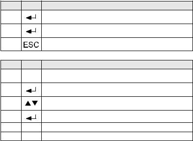
To discard entry and |
|
|
|
|
|
|
|
|
|
|
|
|
|
|
|
|
|
Step |
|
Key/Screen |
Description |
|
|||||||||||||
invalid data entry |
|
|
|||||||||||||||
1. |
|
|
|
|
|
|
|
|
|
|
|
|
|
Press key to discard entry and restore old value. |
|
||
|
|
|
|
|
|
|
|
|
|
|
|
|
|
|
|||
|
|
|
|
|
|
|
|
|
|
|
|
|
|
|
|
|
|
|
2. |
|
|
|
|
|
|
|
|
|
|
|
|
|
When an "INVALID" data is being input, an "Invalid Entry" |
|
|
|
|
|
|
|
|
|
E105 |
|
message is prompted. |
|
|||||||
|
|
|
|
|
|
|
|
|
|||||||||
|
|
|
|
|
|
|
|
|
|||||||||
|
|
|
|
|
|
Invalid Entry ! |
|
|
|||||||||
|
|
|
|
|
|
|
|
|
|
|
|
|
|
|
|
|
|
|
3. |
|
|
|
|
|
|
|
|
|
|
|
|
|
Press key to continue. |
|
|
|
|
|
|
|
|
|
|
|
|
|
|
|
|
|
|
|
|
Accepting character |
|
|
|
If there is no change for any particular character in the existing entry field, press |
|||||||||||||
|
|
|
|||||||||||||||
in the existing value |
|
|
|
ENTER key to accept the old entry. |
|
||||||||||||
|
|
|
|
|
|
|
|
|
|
|
|
|
|
|
|
|
|
User Interface |
|
|
|
|
|
|
SPRINTER 100/100M/200/200M |
25 |
|||||||||

User Interface |
SPRINTER 100/100M/200/200M |
26 |
Clearing all the existing entry field
Default Reference
Reduced Level
Change reduced level value
Highlighting the first entry field with "SPACE" and press ENTER key to clear the entire last reduced level input value.
•If no Reference reduced level is input; the default value equals to zero, i.e. 0.000.
•The display value is to 4 and 3 decimals in meter and feet (Int and US ft) respectively for Precise setting; 3 and 2 decimals in meter and feet (Int and US ft) respectively for Standard setting. For ft in 1/8 inch, the display value will be shown in Precise setting.
•Once Reference staff measurement is measured as in section "5.3.2 Height Difference, Reduced Level, Height and Distance Measurement (internal Memory not active)", then the last input REFERENCE reduced level cannot be changed. At this stage, if any attempt to change the last input REFERENCE reduced level in menu INPUT RL, a "RL Change Not Allowed!" message will be prompted.
•To change the input REFERENCE reduced level, follow these steps:
•Discontinue the present reduced level measurement by pressing HEIGHT/DISTANCE key to exit to default measurement.
•Go to menu select INPUT RL and carry on with the steps in section 4.7.1 to edit a new REFERENCE reduced level value.
•Start reduced level measurement with NEW REFERENCE reduced level as in section "5.3.2 Height Difference, Reduced Level, Height and Distance Measurement (internal Memory not active)".
Loading...