


762767-R
Table of contents
 Loading...
Version 1.2
Roteo 20HV/25H/35/35G
Roteo 20HV/25H/35/35G
User Manual
User Manual
ABC
RRC350
1
4
2
D
8
6
7
3
6
11
10
7
8
5
9
2
3
9
5
1
4
10
1
12
4
6
8
13
10
12
4
6
13
10
12
4
6
13
Roteo 35/35G:
3
2
Roteo 25H:
3
Roteo 20HV:
3
11
5
7
9
1
7
1
7
E
F
1
2
3
4
2
1
9
6
RRC350
4
5
6
7
6
5
3
7
8
1
2
3
4
5
G
HI
J
LM
30 meters (100 feet)
30 meters (100 feet)
X-Axis Y-Axis
KN
(1)
(2)
30 meters (100 feet)
30 meters (100 feet)
(3)
(4)
D
EN
F
I
E
P
NL
DK
S
N
FIN
J
CN
ROK
PL
H
RUS
CZ
User Manual
English
Introduction
Purchase
Congratulations on the purchase of a new Rotating
Laser from Leica Geosystems.
Product
This manual contains important safety
directions as well as instructions for
setting up the product and operating it.
information.
Read carefully through the User Manual before you
switch on the product.
Product identification
The model and the serial number of your product are
indicated on the type plate.
Enter the model and serial number in your manual and
always refer to this information when you need to contact
your agency or Leica Geosystems authorized service
workshop.
Type: ____________ Serial no.: ____________
Note: There are drawings on the first and last
)
page of the user manual. Unfold these pages
while reading through the User Manual. The
letters and numbers in {} always refer to these
drawings.
Refer to "Safety Directions" for further
Symbols
The symbols used in this manual have the following
meanings:
DANGER
Indicates an imminently hazardous situation
which, if not avoided, will result in death or serious injury.
WARNING
Indicates a potentially hazardous situation or an
unintended use which, if not avoided, could result in
death or serious injury.
CAUTION
Indicates a potentially hazardous situation or an
unintended use which, if not avoided, may result in minor
or moderate injury and / or appreciable material, financial and environmental damage.
Important paragraphs which must be adhered to in
)
practice as they enable the product to be used in
a technically correct and efficient manner.
Trademarks
All trademarks are the property of their respective
owners.
Introduction
1
Roteo 20HV/25H/35/35G - 1.2.0en

Contents
Introduction................................................................ 1
Features................................................................... 2
Laser Overview {A}................................................. 3
Keypad Overview {B}.............................................. 3
Carrying Case Overview {C}................................... 3
Basic Operation......................................................... 3
How to use your Roteo............................................ 3
Button Functions......................................... ............. 4
Automatic / Manual modes...................................... 4
H.I. Alert mode......................................................... 5
Rotation mode (Roteo 20HV/35/35G)...................... 5
Scanning mode (Roteo 20HV/35/35G).................... 5
Wall Mount {D} (Roteo 20HV/35/35G) .................... 6
Set-up and applications............................................ 6
Set-up for manual slopes......................................... 6
Set-up for ceiling work............................................. 8
Set-up for layout or floor work
(Roteo 20HV/35/35G).............................................. 8
Set-up for squaring or establishing 90° angles
(Roteo 20HV/35/35G).............................................. 9
Accessories ............................................................... 9
RC-350 Remote Control.......................................... 9
RRC-350 Receiver/Remote Control ........................ 9
R-250 Receiver...................................................... 10
Other accessories.................................................. 10
Batteries................................................................... 10
Low battery Indicator ............................................. 10
Replacing alkaline batteries................................... 10
Using rechargeable NiMH batteries....................... 11
Later recharging..................................................... 11
Check and Adjust .................................................... 11
Notes and Responsibilities .................................... 11
Checking level accuracy........................................ 11
Checking vertical accuracy.................................... 12
Adjusting level accuracy – The X-axis................... 12
Adjusting level accuracy – The Y-axis................... 12
Adjusting vertical accuracy – The Z-axis ............... 13
Check your work................................................... . 13
Troubleshooting...................................................... 14
Care and Transport.................................................. 16
Transport................................................................ 16
Storage .................................................................. 16
Cleaning and Drying .............................................. 17
Safety Directions ..................................................... 17
General..................................................................17
Intended Use.......................................................... 17
Limits of Use..........................................................18
Responsibilities...................................................... 18
Hazards of Use......................................................18
Laser Classification................................................21
Electromagnetic Compatibility (EMC) ....................23
FCC Statement, Applicable in U.S.........................24
Technical Data ......................................................... 26
International Limited Warranty...............................27
Features
The Roteo laser from Leica Geosystems offers the interior contractor many great features to make your work
easier and more accurate. A bright red beam; motorized
wall mount; small, ergonomic remote control; optional
receiver-remote control unit combine to provide consistent value for the professional contractor.
D
EN
F
I
E
P
NL
DK
S
N
FIN
J
CN
ROK
PL
H
RUS
CZ
Roteo 20HV/25H/35/35G - 1.2.0en
2
Introduction

D
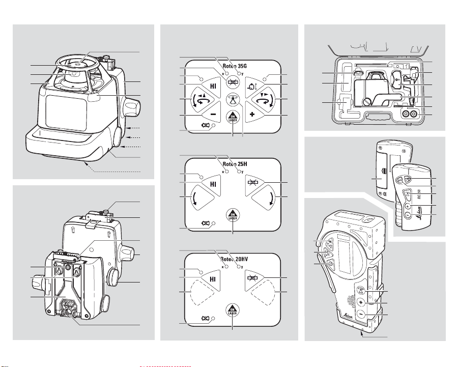
Laser Overview {A}
See the inside front cover for a diagram of the laser {A}
EN
and keypad {B} corresponding to these callouts. See
F
separate descriptions of the motorized wallmount,
remote control and detector.
I
1) Rotating head
2) Aluminum head protection with axes indications
E
3) Plumb or square beam laser beam aperture
4) Rotating laser beam aperture
P
5) Index marks for alignment and 90°
6) Motorized wall or floor mount
NL
7) Batteries
DK
8) Jack for battery charger
9) 5/8"-11 Tripod mount for horizontal setup
S
10)5/8"-11 Tripod mount for vertical setup
11)Sensors for remote control signal
N
FIN
Keypad Overview {B}
The keypad for the Roteo laser has nine buttons and five
J
LED indicators.
CN
1) Automatic / Manual Mode
ROK
RUS
2) Scan / Rotation Mode
3) On / Off
4) H.I. (Elevation) Alert
PL
5) Motorized Mount On / Off
6) CCW Scan-Stationary Beam / Manual Slope
H
7) CW Scan-Stationary Beam / Manual Slope
8) Minus – Head Speed / Scan Width / Motorized Mount
9) Plus – Head Speed / Scan Width / Motorized Mount
10)LED’s – X/Y Axis Level Indicators (2) – Green (self-
CZ
11)LED – Motorized Mount Enabled
Basic Operation
leveling), Red (manual)
12)LED – H.I. Alert
13)LED – Low Battery
Carrying Case Overview {C}
Not all items indicated are included in the standard
package. The following identifies the locations that these
items can be placed in the carrying case.
1) Spare compartment
2) RC350 Remote Control
3) Roteo
4) User Manual
5) Spare Battery Holder
6) RRC350 Receiver-Remote Control (optional)
7) Ceiling Target
8) Spare D-cell Batteries
Basic Operation
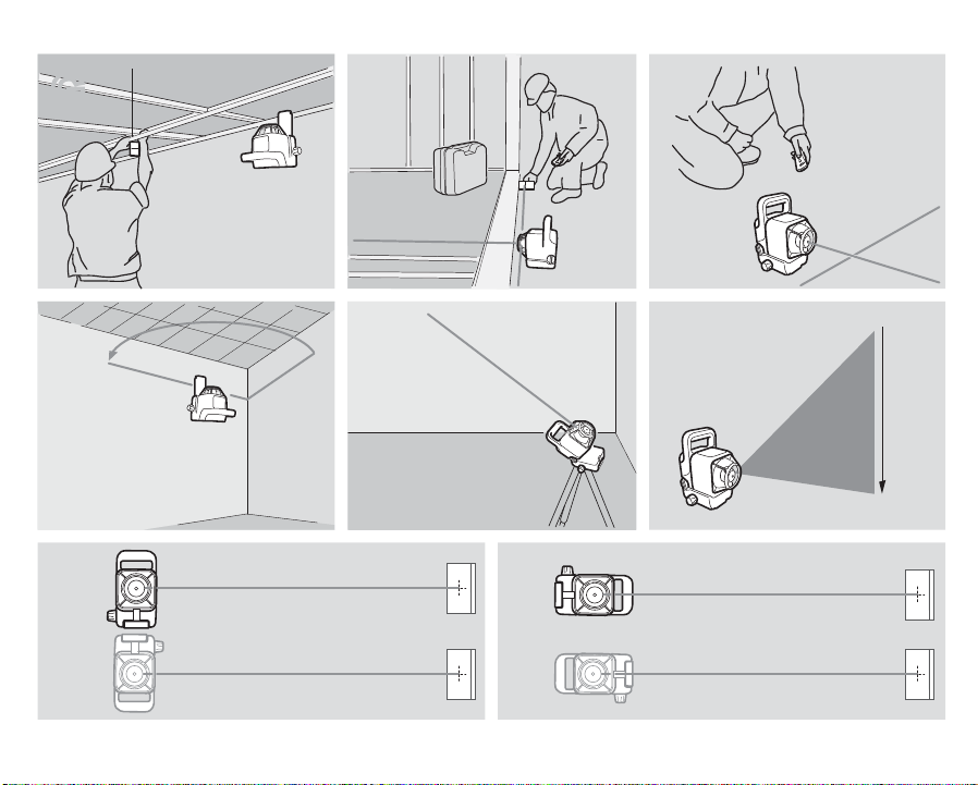
How to use your Roteo
The wall mount and the metal head protection can both
be removed from the laser, if you wish to work without
these attachments.
Horizontal Setup
The laser can be mounted on a 5/8"-11 tripod or placed
directly on a solid, stable surface. Roteo 20/35 can be
suspended from a ceiling grid using the wall mount (see
later section).
Vertical Setup
The laser can be mounted on a 5/8"-11 tripod or placed
directly on its back (opposite the handle) on a solid,
3
Roteo 20HV/25H/35/35G - 1.2.0en
stable surface. For more stability, it is recommended to
use the wall mount. Use the support plate {D-7} for
stability when in vertical mode.
Turning on the laser
Turn on the laser with the On/Off key {B-3}. It does a
self-test and the beam blinks while the laser is selfleveling. After it is leveled, the head rotates. You can
choose H.I. Alert mode or change to manual mode (see
later sections).
The laser has a wide self-leveling range; however, if the
laser is set up out of the leveling range, the laser beam
will continue to blink and the rotation will not start.
X-axis and Y-axis LED indicators
The X and Y-axis LED indicators {B-10} slowly blink
green while the axes are leveling and turn on solid when
each axis has reached a level position. They will rapidly
blink red when in manual mode and the axis can be
adjusted. They will be red and on solid when in manual,
but the axis cannot be adjusted.
Button Functions
The CCW/CW and Plus/Minus buttons on the laser and
the remote control units have multiple functions
depending on the mode of operation. Please refer to the
chart below to better understand their functionality.
Mode CCW / CW Buttons Plus / Minus
Automatic
mode - rotating
Automatic
mode - scanning
Laydown mode
- rotating
Laydown mode
- scanning
Manual mode -
rotating
Manual mode scanning
Motor mount
mode
These fully apply only on Roteo 35. Other models
feature less functions, according the following sections.
Roteo 20HV/25H do not feature all buttons {B} as Roteo
35. Refer to RC350 section later to see how to use
RC350 instead of the {B} buttons.
Moves stationary
beam – CCW/CW
Moves scanning
beam – CCW/CW
Moves vertical
plane – Left/Right
Moves scanning
beam – CCW/CW
Moves manual
slope – Inclines
plane
Moves scanning
beam – CCW/CW
No function Moves the laser
Buttons
Changes head
speed
Changes scan
width
Changes head
speed
Changes scan
width
Changes head
speed
Changes scan
width
- Up/Down
Automatic / Manual modes
The Roteo is in automatic, self-leveling mode when
turned on. Once the instrument has self-leveled, the
D
EN
F
I
E
P
NL
DK
S
N
FIN
J
CN
ROK
PL
H
RUS
CZ
Roteo 20HV/25H/35/35G - 1.2.0en
4
Basic Operation

D
EN
F
I
E
P
NL
DK
S
N
FIN
J
CN
ROK
PL
H
RUS
CZ
laser head will start rotating (Roteo 20HV/35/35G:
300 rpm, Roteo 25H: 600 rpm).
In manual mode, the laser does not self-level; this
means that the beam will rotate even if the laser is not
leveled. It can therefore be used on inclined planes such
as stairs, roofs, or when manual grade setting is
required. See later section on setting slope in manual or
semi-automatic modes.
H.I. Alert mode
The H.I. feature stops the laser automatically and
sounds an alarm if the laser is disturbed, preventing
inaccurate readings. It functions only when selected.
X To activate this safeguard feature, press the H.I. key
{B-4} after turning on the laser. The H.I. LED {B-12}
will blink rapidly while the laser is self-leveling.
X Thirty seconds after the head starts to rotate, the LED
will blink slowly, indicating the H.I. Alert function is
activated.
X If the laser is disturbed while in H.I. Alert mode, the
head will stop rotating, the beam will turn off, the LED
indicator will be on continuously, and an alarm will
sound (Roteo 35/35G).
X On Roteo 20HV and 25H models all LEDs will be on
continuously when disturbed in H.I. mode.
X Press the H.I. key to turn off the H.I. Alert function.
Check to see if the beam elevation has changed from
its original benchmark position.
X The laser is no longer in H.I. Alert mode. Press the H.I.
key to re-activate the H.I. Alert function.
Rotation mode (Roteo 20HV/35/35G)
The head rotates at four speeds: 0, 150, 300, 450, 600
rpm. The default setting is 300 rpm. The laser beam is
more visible at slower rotation speeds.
X To increase the rotation speed press the Plus key
{B-9}. Press the Minus key {B-8} to decrease speed.
Press and hold the Minus key to stop rotation.
X When the beam is stopped, the point can be moved to
the right or left using the Counter-clockwise / Clockwise (CCW/CW) rotation keys {B-6 and B-7}. You can
also move the head manually to position the beam
point. To start rotation again, press the Plus key {B-9}.
Scanning mode (Roteo 20HV/35/35G)
For interior applications, scanning mode allows you to
see the beam easier at a distance.
X To scan press the Scan / Rotation key {B-2}. The
beam will blink until the laser has self-leveled.
X To increase the scan length press the Plus key {B-9}.
Press the Minus key {B-8} to decrease the scan
length.
X The scanning beam can be moved to the right or left
using the Counter-clockwise / Clockwise (CCW/CW)
rotation keys {B-6 and B-7}.
Basic Operation
5
Roteo 20HV/25H/35/35G - 1.2.0en

Wall Mount {D} (Roteo 20HV/35/35G)
See the inside, front cover for illustrations of the Wall
Mount.
1) Attachment clamps for laser and mount
2) Clamp for ceiling grid
3) Adjustable plate
4) 5/8"-11 tripod mount (vertical setup)
5) Moves laser manually on mount
6) Holes for attaching mount to wall
7) Adjustable support for wall or ground stability
8) Screw to adjust support
9) Index notches for alignment The wall mount can be used to move the laser up or down on a ceiling grid. It can also be used when installing walls and partitions to move the laser back and forth for vertical alignment.
Motorized Wall Mount (Roteo 35/35G)
Activating the motorized wall mount
Allow the laser to self-level. Note the position or the
beam.
X Press the Motorized mount key {B-5} to activate the
mount. The motorized mount LED {B-11} will turn on
to indicate that the mount is now active (on the
Remote, press Scan/Rotation key {E-3, F-4} for 1.5
seconds).
X To raise the laser press the Plus key {B-9}. Press the
Minus key {B-8} to lower the laser.
Maximum movement
When the beam is at 0 on the adjustable plate, the laser
can be raised a maximum of 50 mm (2") and lowered a
maximum of 60 mm (2.25").
Wait until self-leveled
While the laser is moving on the mount it does not selflevel and the beam continues to rotate.
X After moving the laser, wait a few seconds in case the
laser needs to self-level. Check that it is still on the
point or level desired and make adjustments if
needed.
Automatic exit from mode
If you have not activated the wall mount for five minutes,
the laser will automatically exit from the motorized mount
mode and return to the previous mode. The Motorized
mount LED will turn off.
Troubleshooting
X If the laser does not move on the mount, check that
the knobs {D-1} are tight enough to make the power
contact for the motor. The mount can also be
detached to check that the contacts are clean where
the laser and mount.
Set-up and applications
Set-up for manual slopes
The Roteo can be used to manually create slopes for
special applications, stairways, sloped ceilings, etc.
D
EN
F
I
E
P
NL
DK
S
N
FIN
J
CN
ROK
PL
H
RUS
CZ
Roteo 20HV/25H/35/35G - 1.2.0en
6
Set-up and applications

D
EN
F
I
E
P
NL
DK
S
N
FIN
J
CN
ROK
PL
H
RUS
CZ
Two modes are available:
• Full manual mode – Both the X and Y-axes will be in
manual mode
• Semi-automatic mode – The X-axis self-levels, The Yaxis is in manual mode.
For slopes up to 10%, set up the laser in horizontal mode
and use the remote to set the slope following the instructions below.
For slopes greater than 10%, set up the laser in vertical
mode and use the inclined plane feature explained in the
following section.
Set-up for full manual mode
In full manual mode, the unit will not self-level and the
head will continue to rotate. The plane of laser light can
be tilted in either one or both planes.
To use the laser in full manual mode:
X After turning the laser on and allowing it to self-level,
press the Auto/Manual key {B-1}. The X-axis LED
{B-10} above the key will blink red rapidly, indicating
that you are in manual mode and you can set slope in
the X-axis. (The Y-axis LED will also be on and red.)
X Turn the laser so that the X on the top of the laser
faces the direction of the slope.
X Press either CCW/CW (manual slope) keys {B-6 or
B-7} to adjust the slope of the X-axis.
X To adjust the slope of the Y-axis, press the Auto/
Manual key {B-1} again. The Y-axis LED {B-10}
above the key will blink red rapidly, indicating that you
are in manual mode and you can set slope in the Yaxis. (The X-axis LED will also be on and red.)
X Turn the laser so that the Y on the top of the laser
faces the direction of the slope.
X Press either CCW/CW (manual slope) keys {B-6 or
B-7} to adjust the slope of the Y-axis.
X Press the Auto/Manual key {B-1} for 1.5 seconds to
exit manual mode and return to automatic mode. See
illustration {J} in the back, inside cover of this manual.
Set-up for semi-automatic mode
In semi-automatic mode, the unit will self-level in the Xaxis. The plane of laser light can be tilted manually in the
Y-axis.
To use the laser in semi-automatic mode:
X After turning the laser on and allow the laser to self-
level, press and hold the Auto/Manual key {Roteo 35/
35G: B-1, Roteo 20HV/25H: E-3} for three seconds.
Roteo 20HV/25H: The X-axis LED {B-10} above the
key will blink green slowly while leveling. The Y-axis
LED will blink quickly indicating that the Y-axis is in
manual mode and you can set slope in the Y-axis.
X Turn the laser so that the Y on the top of the laser
faces the direction of the slope.
X Press either CCW/CW (manual slope) keys {B-6 or
B-7} to adjust the slope of the Y-axis.
X Press the Auto/Manual key {B-1} again to exit semi-
automatic mode and return to automatic mode.
Set-up for inclined planes (Roteo 20HV/35/
35G)
The Roteo can also be tilted, for manual slope, at various
angles on the wall mount. A tripod with rotating mounting
plate will speed set-up.
Set-up and applications
7
Roteo 20HV/25H/35/35G - 1.2.0en
Loading...