

Page 1

LV 58SER40A
LV 58SER40
DIGITAL AUDIO
INSTRUCTION MANUAL
Page 2

Contents
1. INTRODUCTION.......................................................................................................... 1
1.1 Maximum Allowable Input V
1.2 Conv
1.3 T
entions.............................................................................................................................. 1
rademark Acknowledgments................................................................................................... 1
2. SPECIFICATIONS ....................................................................................................... 2
2.1 General
2.2 Features
2.3 S
pecifications............................................................................................................................ 3
2.3.1 Input and Output Signals
2.3.2 Rear BNC Connectors
2.3.3 Analog Audio Input
2.3.4 W
2.3.5 Correlation Meter
2.3.6 Meter Display
2.3.7 S
2.3.8 Loudness Display
2.3.9 Head
2.3.10 General S
..................................................................................................................................... 2
................................................................................................................................... 2
aveform Displays............................................................................................................ 3
..................................................................................................................... 4
tatus Display.................................................................................................................... 4
phone Output ............................................................................................................ 5
pecifications....................................................................................................... 5
oltage ............................................................................................ 1
................................................................................................... 3
....................................................................................................... 3
............................................................................................................ 3
............................................................................................................... 3
.............................................................................................................. 5
3. COMPONENT NAMES AND FUNCTIONS .................................................................. 6
4. MENU STRUCTURE ................................................................................................... 8
5. OPERATING PROCEDURE ...................................................................................... 12
5.1 Precautions
5.1.1 Inst
5.1.2 Multi Screen Display
5.2 Audio Signal
5.2.1 T
5.2.2 T
5.2.3 T
5.2.4 T
5.2.5 T
5.2.6 T
5.2.7 T
5.3 T
5.4 Head
ransmitting Audio Signals .....................................................................................................24
5.3.1 T
5.3.2 T
5.3.3 T
5.3.4 T
phone Output .................................................................................................................29
............................................................................................................................. 12
alling the Unit ............................................................................................................. 12
........................................................................................................ 12
Measurement..................................................................................................... 13
o Measure Audio Signals That Are Embedded in SDI Signals....................................... 17
o Measure Dolby Signals That Are Embedded in SDI Signals....................................... 18
o Measure Audio Signals That Are Embedded in DVB-ASI Signals............................... 19
o Measure Dolby Signals That Are Embedded in DVB-ASI Signals .............................. 20
o Measure Audio Signals That Are Received through the Rear Panel BNC Connectors21
o Measure Dolby Signals That Are Received through the Rear Panel BNC Connectors22
o Measure Analog Audio Signals ................................................................................... 23
o Transmit Audio Signals That Are Embedded in SDI Signals ....................................... 25
o Transmit Dolby Signals That Are Embedded in SDI Signals ....................................... 26
o Transmit Audio Signals That Are Embedded in DVB-ASI Signals............................... 27
o Transmit Dolby Signals That Are Embedded in DVB-ASI Signals............................... 28
6. MEASUREMENT DISPLAYS ..................................................................................... 30
6.1 Lissaj
6.1.1 Lissaj
ous Display.................................................................................................................... 30
ous Display Screen ................................................................................................ 30
Page 3

6.1.2 Configuring the Lissaj
6.2 Surround Display
6.2.1 Surround Display
6.2.2 Configuri
6.3 S
6.4 Meter Display
6.5 Loudness Display (LV 58SER40A only)
tatus Display......................................................................................................................... 39
6.3.1 S
6.3.2 Configuring the S
6.4.1 Meter Display
6.4.2 Configuring the Meter Display
6.5.1 Loudness Display Screen
6.5.2 Configuring the Loudness Display
tatus Display Screen .....................................................................................................39
.................................................................................................................... 36
ng the Surround Display.................................................................................... 37
.......................................................................................................................... 72
Screen ...................................................................................................... 72
ous Display.................................................................................... 32
Screen................................................................................................. 36
tatus Display......................................................................................... 43
......................................................................................... 74
.................................................................................. 77
................................................................................................ 77
................................................................................... 79
7. CONFIGURATION ..................................................................................................... 85
7.1 Selecting Measurement Channels
7.2 Configuring the Head
7.3 Dolby
7.4 Configuri
7.5 Sy
Setup ............................................................................................................................ 88
ng the Input Signal Settings...................................................................................... 90
stem Configuration .............................................................................................................91
phone Settings ...................................................................................... 86
.......................................................................................... 85
8. FIRMWARE REVISION HISTORY............................................................................. 93
Index
Page 4

1. INTRODUCTION
1. INTRODUCTION
1.1 Maximum Allowable Input Voltage
Table 1-1 indicates the maximum allowable voltage that can be applied to the input
connectors.
Do not apply excessive voltage, because doing so may damage the instrument.
Table 1-1 Maximum allowable input voltage
Input Connector Maximum Input Voltage
AES/EBU IN/OUT ± 5 V
1.2 Conventions
In this manual, the LV 58SER01A (SDI INPUT) is used to represent both the LV 58SER01A
(SDI INPUT) and the LV 58SER01 (SDI INPUT unit). The LV 5800 operates in the same
manner regardless of whether which unit is installed.
In this manual, the LV 58SER40(A) (DIGITAL AUDIO) is used to represent both the LV
58SER40A (DIGITAL AUDIO) and the LV 58SER40 (DIGITAL AUDIO unit). The LV 5800
operates in the same manner regardless of whether which unit is installed.
The combination of an LV 58SER01A (SDI INPUT) and this unit operates in the same manner
as the combination of an LV 58SER06 (3G-SDI INPUT) and this unit. If you have an LV
58SER06, read LV 58SER06 in this manual as LV 58SER01A.
1.3 Trademark Acknowledgments
Dolby is a trademark of Dolby Laboratories.
1
Page 5

2. SPECIFICATIONS
2.1 General
The LV 58SER40(A) (DIGITAL AUDIO) operates as an AES/EBU I/O unit when installed in an
LV 5800 input slot or the LV 7800 or as an AES/EBU output unit when installed in an LV 5800
output slot. It allows the LV 5800 to display Lissajous, surround, level meter, signal status,
1
and loudness
audio channels.
If the LV 58SER01A (SDI INPUT) is installed in the LV 5800/7800, this unit can process
AES/EBU signals that are embedded in SDI signals. If the LV 58SER04 (MPEG DECODER)
is installed, this unit can process MPEG-1 Layer 2 signals, MPEG-2 AAC signals, and LPCM
signals that are embedded in DVB-ASI signals.
*1 The LV 58SER40 does not support loudness displays and measurements of analog audio signals.
*2 All AES/EBU signals must be synchronized. This unit only supports 48-kHz sampling frequency.
*3 The standard LV 58SER40(A) provides 4 AES/EBU channel pairs (8 channels). Installing the optional
I/O expansion unit expands the I/O connectors to 8 AES/EBU channel pairs (16 channels).
2.2 Features
displays2 for data in 8 AES/EBU channel pairs (16 channels)3 and 2 analog
1
2. SPECIFICATIONS
● 8 AES/EBU I/O Pairs (16 Channels)
The LV 58SER40(A) is equipped with 4 AES/EBU channel pairs (8 channels). Installing
the optional I/O expansion unit expands the I/O connectors to 8 AES/EBU channel pairs
(16 channels). This unit operates as an AES/EBU I/O unit when installed in an LV 5800
input slot or the LV 7800 or as an AES/EBU output unit when installed in an LV 5800
output slot.
● Headphone Output
When you install this unit into an LV 5800 input slot or the LV 7800, you can listen to the
audio of the selected channel using headphones.
● Various Display Features
This unit enables the LV 5800 to display the following items on the AES/EBU input
signals.
• Single Lissajous display between any two channels
• Multi Lissajous display that simultaneously shows four or eight single Lissajous
displays of different channel pair combinations.
• Surround display
• Meter display
• Loudness display (LV 58SER40A only)
The unit also enables the LV 5800 to display the following AES/EBU signal status bits.
• Channel status bit
• User bit
• Validity bit
• Parity bit
* You cannot assign the audio measurement display to multiple areas.
● Analog Audio Input
The LV 58SER40A can measure analog audio signals on two channels.
2
Page 6

2.3 Specifications
2.3.1 Input and Output Signals
Supported Formats IEC60958, Dolby E (option), Dolby Digital (option)
Sampling Frequency 48 kHz
2.3.2 Rear BNC Connectors
Maximum Input Voltage ± 5V (DC + ACpeak)
Output Voltage 1.0 Vp-p ± 10 % (into 75 Ω)
I/O Connectors BNC connectors (eight channels in four-channel pairs)
Input/Output Impedance 75 Ω
Input and Output Switching Whether to use the connectors as audio signal input
2.3.3 Analog Audio Input
2. SPECIFICATIONS
connectors or as output connectors for audio signals that
are embedded in SDI or DVB-ASI signals is selectable
on the LV 5800/7800.
Maximum Input Voltage +18 dBm (6.2 Vrms)
Input Connector D-Sub 25-pin connector on the LV 5800/7800
Input Impedance At least 5 kΩ
* The LV 58SER40 does not support analog audio input.
2.3.4 Waveform Displays
Lissajous Display Single Lissajous display between any two channels
Surround Display
Channel Mapping L, R, C, LFE, Ls, Rs, Lt, Rt
Surround Formats NORMAL, PHANTOM C
2.3.5 Correlation Meter
Correlation Meter Displays the correlation between two channels in the
(DC-coupled balanced input)
Multi Lissajous display that simultaneously shows four or
eight single Lissajous displays of different channel pair
combinations.
range of -1 to 1
3
Page 7

2.3.6 Meter Display
Meter Display
During Multi Lissajous Display
During Single Lissajous Display
Response Mode Selection
LV 58SER40A TRUE PEAK, PPM type I, PPM type II, VU
LV 58SER40 TRUE PEAK, PPM, VU
Peak Hold Mode Selection
LV 58SER40A TRUE PEAK, PPM type I, PPM type II
LV 58SER40 TRUE PEAK, PPM
Peak Hold Time 0.0 to 5.0 s (in 0.5-s steps), HOLD
Display dynamic range
Reference Level Setting -40.0 to 0.0 dBFS
Warning Level Setting -40.0 to 0.0 dBFS
Over Level Setup -40.0 to 0.0 dBFS
*1 The LV 58SER40 PPM (Peak Program Meter) and the LV 58SER40A PPM type I are equivalent.
*2 Fixed at -60 dBFS when measuring an analog audio signal.
2.3.7 Status Display
2. SPECIFICATIONS
Displays the levels of 8 channels or 16 channels on a bar
graph
Displays the levels of 2 selected channels on a bar
graph
1
1
(when the meter response model is VU)
2
-60 dBFS, -90 dBFS
Channel Status Bit Display Dump display, text display
User Data Bit Display Dump display
Dolby E Metadata Display Text display
Dolby Digital Metadata Display Text display
Error Detection Counts the number of errors for each channel
Level Over Detection Counts the number of times the input signal level
exceeds the specified level
Detection Setting -40.0 to 0.0 dBFS
Clip Detection Detects an error when the number of maximum signal
values that are received consecutively exceeds the
specified number of samples and counts the number of
times this error occurs
Detection Setting 1 to 100 samples
Mute Detection Detects an error when the length of a received mute
signal exceeds the specified duration, and counts the
number of times this error occurs
Detection Setting 1 to 5000 ms
Parity Error Detection Counts the number of times the input signal parity bit
differs from the parity bit value that the LV 58SER40(A)
calculates
Validity Error Detection Counts the number of times the input signal validity bit is
1
4
Page 8

CRC Error Detection Counts the number of times the input signal CRC value
Code Violation Detection Counts the number of times the input signal bi-phase
2.3.8 Loudness Display
Function Displays total loudness values on a graph
Measurement time 2min, 10min, 30min, 1hour, 2hour
2.3.9 Headphone Output
Headphone Output You can transmit the audio of the selected channel
2.3.10 General Specifications
2. SPECIFICATIONS
differs from the CRC value that the LV 58SER40(A)
calculates
modulation status is in error
Values are displayed in red if they exceed the threshold
through the LV 5800/7800 headphone jack.
Environmental Conditions The same as the LV 5800/7800
Power Consumption 9 Wmax. supplied from the LV 5800/7800
Weight 0.27 kg
Accessories Instruction manual ......................................... 1
Analog audio cable (LV 58SER40A only) ...... 1
5
Page 9
3. COMPONENT NAMES AND FUNCTIONS
3. COMPONENT NAMES AND FUNCTIONS
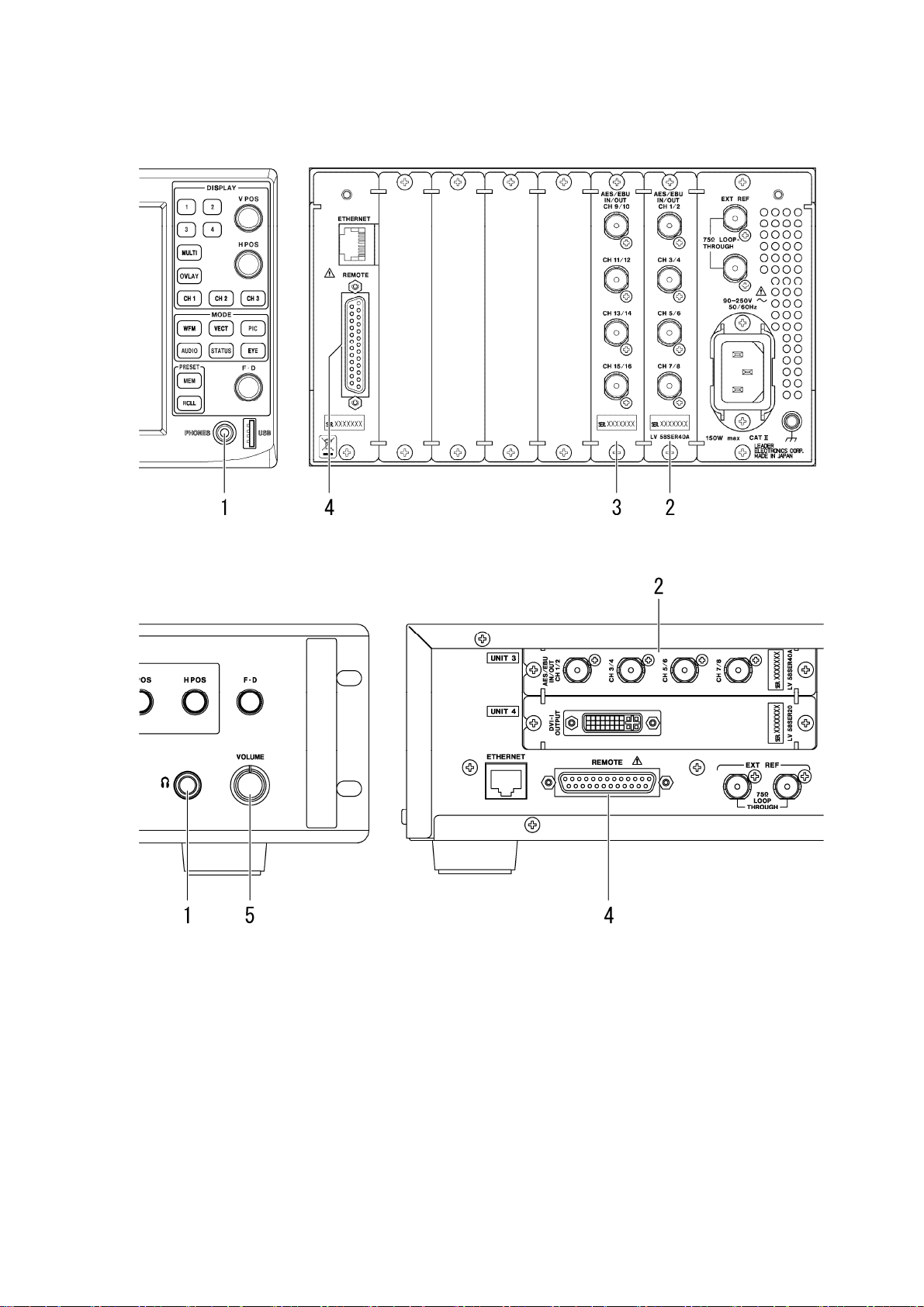
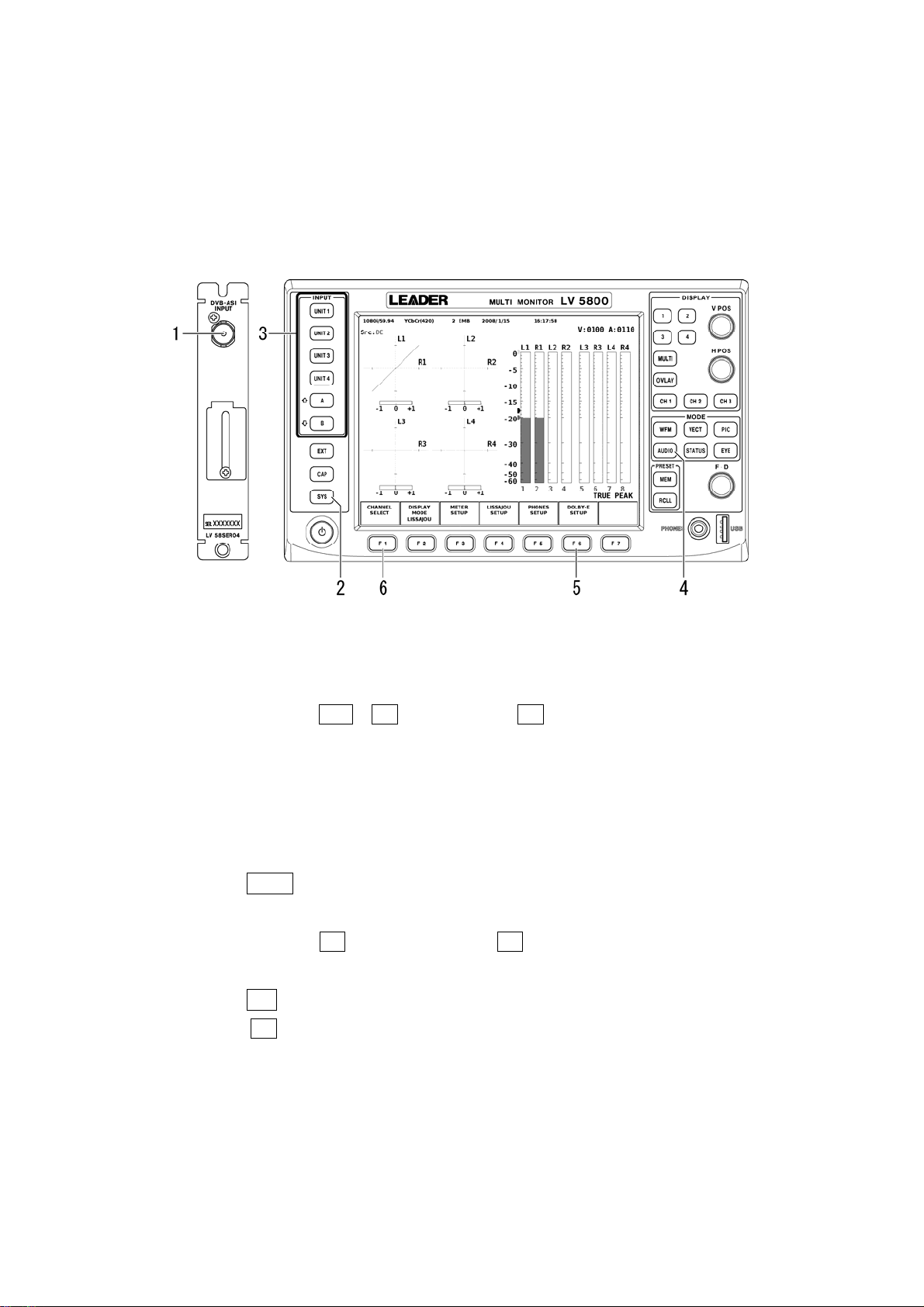
The following figures illustrate the front and rear panels of the LV 5800/7800.
Figure 3-1 LV 5800 panel diagrams
Figure 3-2 LV 7800 panel diagrams
6
Page 10

3. COMPONENT NAMES AND FUNCTIONS
1 Headphone connector (PHONES)
The LV 5800 has a 3.5 mm stereo mini jack. The LV 7800 has a 6.5 mm standard stereo
jack.
If the LV 58SER01A is installed in an LV 5800 input unit (UNIT 1 to 4) or the LV 7800, these
connectors transmit the audio signals of the selected channels.
See section 5.4, “Headphone Output” and section 7.2, “Specifying the Headphone Settings”
2 Audio Signal I/O Connectors (AES/EBU IN/OUT CH1/2 to CH7/8)
I/O connectors for digital audio signals. Eight channels of audio signals received here can
be measured.
If the LV 58SER01A is installed, these connectors can transmit audio signals
that are embedded in SDI signals. If the LV 58SER04 is installed, these connectors can transmit
audio signals that are embedded in DVB-ASI signals.
You can change the functionality of the connectors between input and output in system
setup.
See: Section 5.2.5, “To Measure Audio Signals That Are Received through the Rear Panel BNC
Connectors”
Section 5.3.1, “To Transmit Audio Signals That Are Embedded in SDI Signals”
Section 5.3.3, “To Transmit Audio Signals That
Section 7.5, “System Setup”
Are Embedded in DVB-ASI Signals”
3 Optional Audio Signal I/O Connectors (AES/EBU IN/OUT CH9/10 to CH15/16)
The optional I/O expansion unit. These optional connectors enable you to measure 16
channels of audio signals in combination with the LV 58SER40A. If the LV 58SER01A is
installed, these connectors can transmit audio signals that are embedded in SDI signals. If
the LV 58SER04 is installed, these connectors can transmit audio signals that are
embedded in DVB-ASI signals.
You can change the functionality of the connectors between input and output in system
setup.
See: Section 5.2.5, “To Measure Audio Signals That Are Received through the Rear Panel BNC
Connectors”
Section 5.3.1, “To Transmit Audio Signals That Are Embedded in SDI Signals”
Section 5.3.3, “To Transmit Audio Signals That
Section 7.5, “System Setup”
Are Embedded in DVB-ASI Signals”
4 Remote Connector (REMOTE)
The remote connector is used to receive analog audio signals and to start and stop
loudness measurements. The LV 58SER40A is required in both situations.
See: Section 5.2.7, “To Measure Analog Audio Signals”
Section 6.5, “Loudness Display (LV 58SER40A only)”
Section 7.4, “Input Signal Setup”
5 Volume Knob (VOLUME)
Adjusts the headphone volume.
There is no volume knob on the LV 5800. You can adjust the headphone volume from a
menu.
7
Page 11

4. MENU STRUCTURE
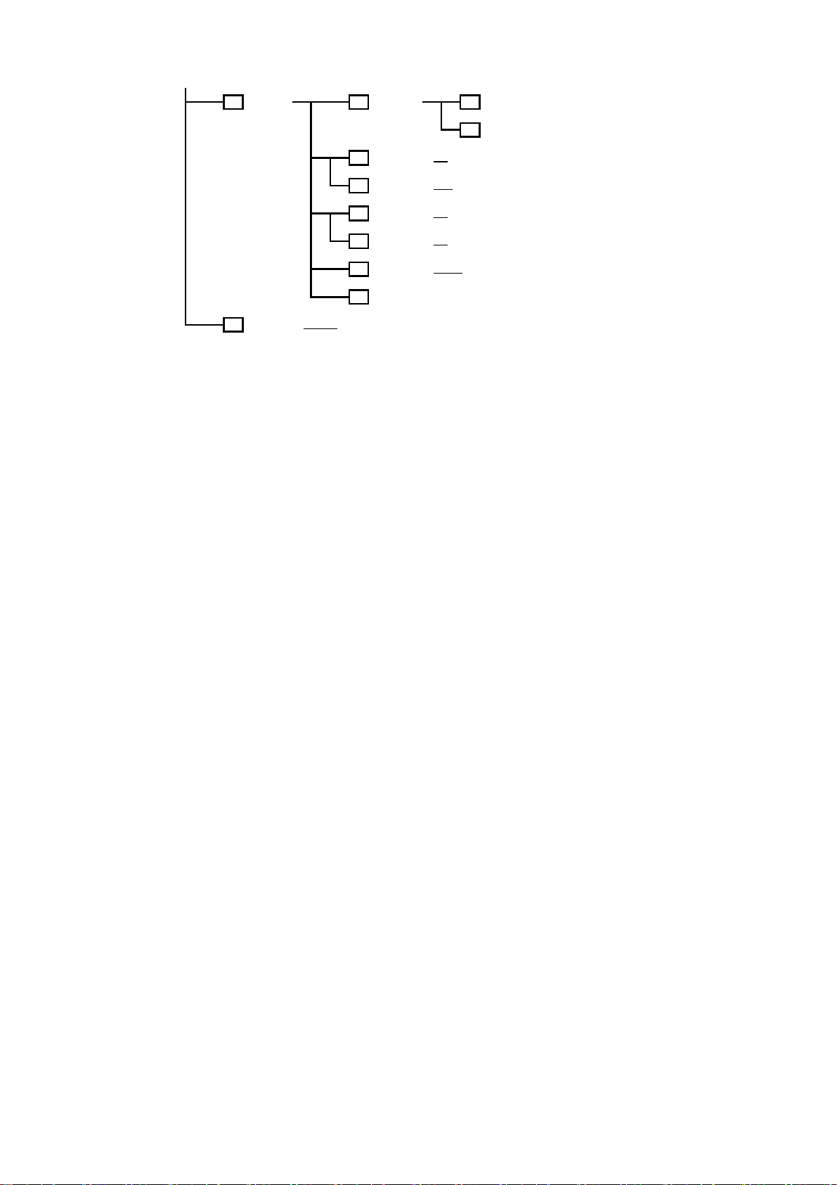
The following figure shows the menu structure for the AUDIO key. Underlined values are default
values.
The menus that are displayed and the available options vary depending on the current settings.
AUDIO F1
CHANNEL
SELECT
DISPLAY
F2
MODE
METER
F3
SETUP
LISSAJOU
F4 F1
SETUP
( LISSAJOU
4. MENU STRUCTURE
No. of
F1
CHANNELS
DISPLAY
F2
CHANNELS
F3
MIX MODE
up
F7
menu
/ SURROUND / STATUS / METER / LOUDNESS )
DYNAMIC
F1
RANGE
F2
RESPONSE
PEAK
F3
HOLD
METER
F6
SETTING
up
F7
menu
LISSAJOU
INTEN
SCALE
F2
INTEN
F3
DISPLAY
( 8ch
/ 16ch )
/ 9-16ch )
( 1-8ch
/ ON )
( OFF
( -60dBFS
( TRUE PEAK
VU+PPM(II) / PPM / VU+TRUE / VU+PPM )
( 0.0 - 0.5
( -128 - 0
( -8 - 4
( SINGLE / MULTI
/ -90dBFS / M A G )
/ PPM(I) / PPM(II) / VU+TRUE / VU+PPM(I) /
- 5.0 / HOLD )
F1
COMPLETE
F7
CANCEL
- 127 )
- 7 )
)
SURROUND
F4 F1
SETUP
F4
F5
F6
F7
F2
F3
F5
F6
F7
FORM
AUTO
GAIN
CHANNEL
MAPPING
up
menu
SURROUND
INTEN
SCALE
INTEN
SURROUND
5.1
AUTO
GAIN
CHANNEL
MAPPING
up
menu
( X-Y
/ MATRIX )
/ OFF )
( ON
F1
F2
F3
F7
( -128 - 100
- 7 )
( -8 - 4
/ PHANTOM C )
( NORMAL
/ OFF )
( ON
F1
F7
COMPLETE
PREV
TAB
NEXT
TAB
CANCEL
- 127 )
COMPLETE
CANCEL
8
Page 12

4. MENU STRUCTURE
STATUS
F4
SETUP
DOLBY E
F1
METADATA
DOLBY D
F1
METADATA
EBI
F2
METADATA
CHANNEL
F3
STATUS
USER
F4
BIT
EVENT
F5 F2
LOG
F1
F7
F7
F1
F7
F1
F2
F7
F1
F2
F7
F3
F4
F6
DOLBY
PROGRAM
up
menu
up
menu
DISPLAY
PROGRAM
up
menu
DISPLAY
CHANNEL
ALIGN
up
menu
DISPLAY
CHANNEL
ALIGN
up
menu
LOG
CLEAR
LOG
MODE
USB
MEMORY
/ PRM2 / PRM3 / PRM4 /
( PRM1
PRM5 / PRM6 / PRM7 / PRM8 )
( PRM1
/ PRM2 / PRM3 / PRM4 /
PRM5 / PRM6 / PRM7 / PRM8 )
/ 2 / 3 / 4 / 5 / 6 / 7 / 8 /
( 1
9 / 10 / 11 / 12 / 13 / 14 / 15 / 16 )
( LSB 1st
( 1
9 / 10 / 11 / 12 / 13 / 14 / 15 / 16 )
( LSB 1st / MSB 1st )
( START / STOP
( OVER WR
/ MSB 1st )
/ 2 / 3 / 4 / 5 / 6 / 7 / 8 /
)
/ STOP )
NAME
F1
INPUT
CLEAR
F1
ALL
F2
DELETE
F3
INSERT
F4
<=
F5
=>
CHAR
F6
SET
up
F7
menu
OVER WR
( ON / OFF
F1
F3
F1
F3
)
YES
OVER WR
NO
DELETE
YES
DELETE
NO
F2
STORE
FILE
F4
DELETE
FILENAME
F5
AUTO INC
up
F7
menu
up
F7
menu
ERROR
F6
RESET
up
F7
m
enu
9
Page 13

4. MENU STRUCTURE
F4
F5
LOUDNESS
SETUP
PHONES
SETUP
F1
F2
F3
F4
F5
F6
F7
F1
F2
F5
F6
F7
PERIOD
CHART
CLEAR
MEASURE
TARGET
LV MAG
LOUDNESS
SETTING
USB
MEMORY
up
menu
PHONES
VOLUME
PHONES
L/Rch
AUX CH
AUX CH
DRC
up
menu
( 2min
/ 10min / 30min / 1hour / 2hour )
/ START )
( STOP
/ ON )
( OFF
F1
COMPLETE
PREV
F2
TAB
NEXT
F3
TAB
F7
CANCEL
NAME
F1 F1
INPUT
F2
STORE
FILE
F4
DELETE
FILENAME
F5
AUTO INC
up
F7
menu
( -128 - 64
( 1/2
D1/D2 / D3/D4 / D5/D6 / D7/D8 / DAUX1/DAUX2 / L/R )
( LtRt
( LINE
- 127 )
/ 3/4 / 5/6 / 7/8 / 9/10 / 11/12 / 13/14 / 15/16 / Lt/Rt
/ LoRo / MONO / MUTE )
/ RF )
( ON / OFF
F2
F3
F4
F5
F6
F7
F1
F3
F1
F3
)
CLEAR
ALL
DELETE
INSERT
<=
=>
CHAR
SET
up
menu
OVER WR
YES
OVER WR
NO
DELETE
YES
DELETE
NO
10
Page 14
4. MENU STRUCTURE
DOLBY-E
F6 F1
SETUP
INPUT
F7
SELECT
( DIGITAL
CHANNEL
SETTING
DOLBY E
F2
DIALNORM
DOLBY D
F2
LISTENING
DOLBY E
F3
PULLDOWN
DOLBY D
F3
PROLOGIC
DOLBY D
F4
DRC
up
F7
menu
/ ANALOG )
F1
COMPLETE
F7
CANCEL
/ ON )
( OFF
( FULL
/ EX / 3stereo / PHANTOM / STEREO / MONO )
( OFF
/ ON )
( OFF
/ ON )
( BYPASS
/ LINE / RF )
Figure 4-1 Menu structure
11
Page 15

5. OPERATING PROCEDURE
5. OPERATING PROCEDURE
5.1 Precautions
5.1.1 Installing the Unit
The following table indicates how you can install the unit in the LV 5800 and the
corresponding features that will be available. For the installation procedure, see the LV
5800 Instruction Manual.
You can only install one LV 58SER40(A) in the LV 7800. The features that are available for
the LV 7800 are those listed in the “1” row in the table below.
For the LV 7800, the LV 58SER40 is a factory option.
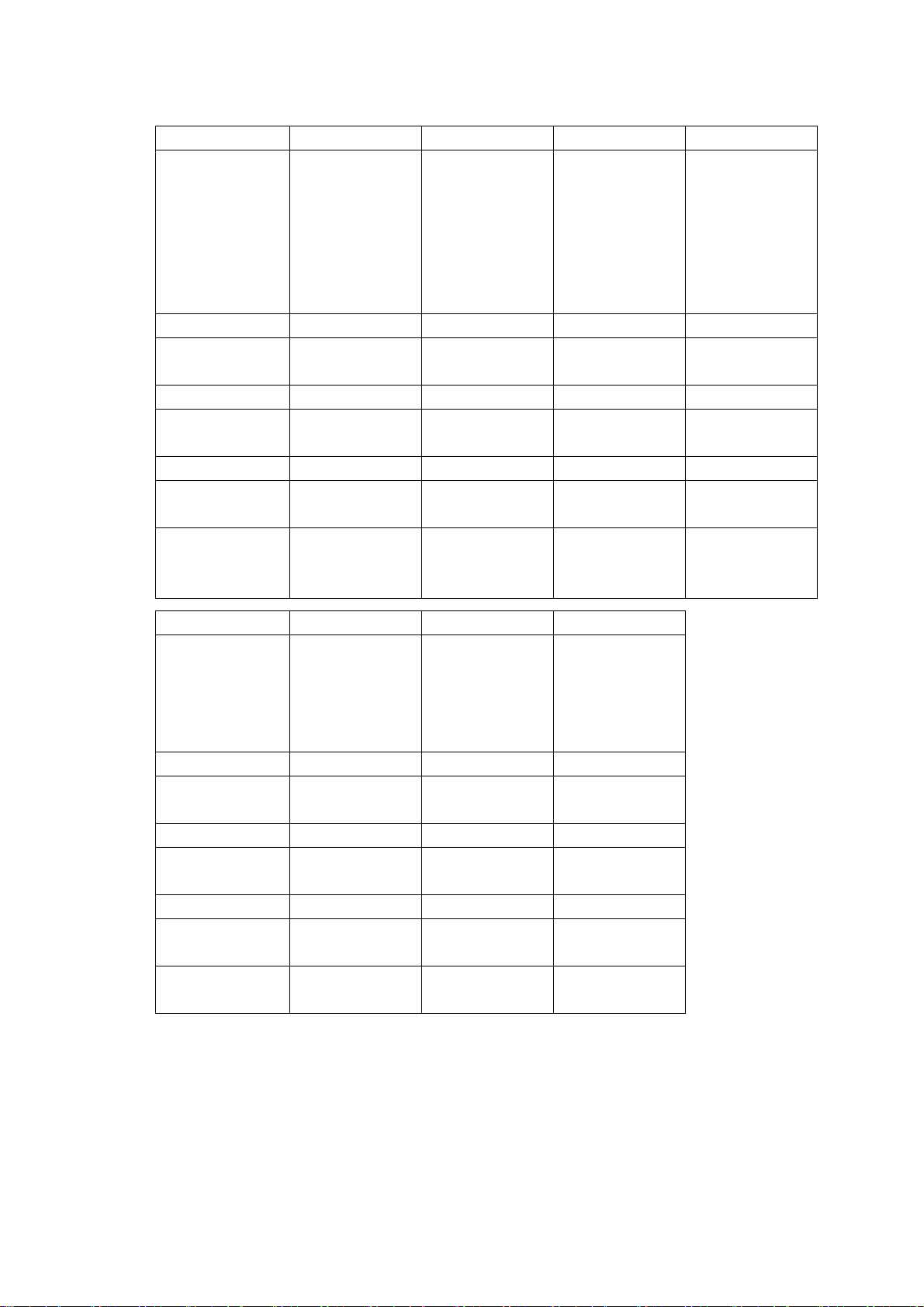
Table 5-1 Unit installation slots and corresponding features
Number
of Units
12 Slots 1 to 4 Yes Yes - Yes
23
33
4 or more Not allowed
Installation
Slots
1 Slots 1 to 4 Yes -
2 Slot 5 or 6
1 Slots 1 to 4 Yes -
2 Slot 5 Yes Yes
3 Slot 6
1 A feature that transmits audio signals received from BNC connectors on an input slot (from UNIT 1 to
UNIT 4) to BNC connectors on an output slot (UNIT 5 or UNIT 6).
2 Audio signals are not transmitted if this unit is installed only to an output slot (UNIT 5 or UNIT 6).
3 If both the LV 58SER40 and the LV 58SER40A are available, install the LV 58SER40A into an input
slot (from UNIT 1 to UNIT 4). You cannot install two or more of this unit into input slots (from UNIT 1
to UNIT 4).
5.1.2 Multi Screen Display
Audio Signal
Measurement
Yes
Yes
Transmission of
Audio Signals
Embedded in
SDI or DVB-ASI
signals
Yes Yes
Yes Yes
Transmission of
Audio Signals
Received through
a Rear BNC
1
Connector
Headphone
Output
Yes
Yes
You cannot assign the audio measurement screen to multiple areas when using the
2-screen or 4-screen multi display. If you specify the audio screen in another area when
there is already an area displaying the audio measurement screen, the original screen
displaying the audio measurement screen will automatically switch to the WFM screen or
will display an error message.
12
Page 16

5. OPERATING PROCEDURE
Measurement of audio signals embedded in Measurement of audio signals received
SDI signals through a rear BNC connector
Figure 5-1 Multi display of the audio measurement screen
5.2 Audio Signal Measurement
The following signals can be measured when this unit is installed in an input slot (from UNIT 1
to UNIT 4).
a Audio signals that are embedded in SDI signals See section 5.2.1
Dolby signals that are embedded in SDI signals See section 5.2.2
b
Audio signals that are embedded in DVB-ASI signals See section 5.2.3
c
Dolby signals that are embedded in DVB-ASI signals See section 5.2.4
d
Audio signals that are received through the rear panel BNC connectors
e
See section 5.2.5
Dolby signals that are received through the rear panel BNC connectors
f
See section 5.2.6
Analog audio signals (LV 58SER40A only) See section 5.2.7
g
ou must configure the LV 5800 appropriately to measure these input signals. This section
Y
explains the relevant settings and displays. For detailed setup procedures, see the
subsequent chapters.
The setting explanations in this section are for the LV 5800, but the same settings can be
performed on the LV 7800.
13
Page 17

5. OPERATING PROCEDURE
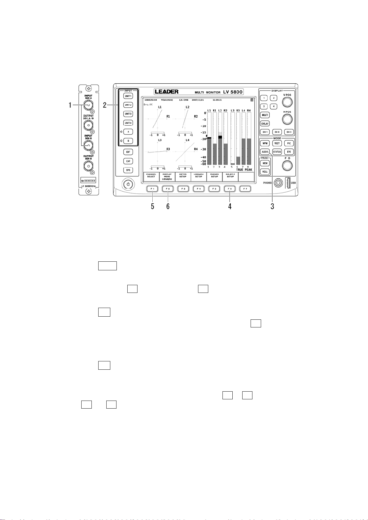
Figure 5-2 Audio signal measurement
1 INPUT
Select the slot (from UNIT 1 to UNIT 4) where the unit receiving the audio signal is
installed and the channel receiving the SDI signal (LV 58SER01A only) or the PID that
you want to decode (LV 58SER04 only). To measure analog audio signals, select the slot
number in which the LV 58SER40A is installed.
2 SYS
If this unit is installed in an input slot (from UNIT 1 to UNIT 4), the functionality of its BNC
connectors can be switched between input and output. To do so, press: SYS > F•1 UNIT
SETUP > F•# UNIT#* SETUP. Then, set External BNC in the UNIT SETUP screen to
INPUT or OUTPUT.
To measure audio signals that are received through the rear panel BNC connector, select
INPUT. You can select either INPUT or OUTPUT to measure audio signals or analog
audio signals that are embedded in SDI or DVB-ASI signals.
See section 7.5, “System Setup”
* Select the unit number in which the LV 58SER40(A) is installed.
3 DOLBY-E SETUP
This menu appears when the Dolby E option is installed.
Press F•6 DOLBY-E SETUP > F•1 CHANNEL SETTING to display the DOLBY-E setup
screen. Set DECODE MODE to OFF, DOLBY-E, DOLBY-DIGITAL according to the input
signal.
See section 7.3, “Dolby Setup”
4 INPUT SELECT
This menu appears when you select a slot number in which the LV 58SER40A is
installed in “1 INPUT.” Select DIGITAL or ANALOG according to the input signal.
See section 7.4, “Input Signal Setup”
14
Page 18

5. OPERATING PROCEDURE
5 Input signal indication
The signal that is currently being measured is displayed at the top section of the screen
as follows:
• EMB If you select a slot number in which the LV 58SER01A or LV 58SER04 is
installed in “1 INPUT.”
• BNC If you select a slot number in which the LV 58SER40(A) is installed in “1
INPUT.”
• ANA If you select ANALOG in “4 INPUT SELECT.”
6 Src indication
The type of signal that is currently being measured is displayed at the top of the screen
as follows (signal indications may be combined, as in “AES/DE”):
• AES If you select OFF in “3 DOLBY-E SETUP” or if the Dolby E option is not
installed.
• DE If you select DOLBY-E in “3 DOLBY-E SETUP”
• DD If you select DOLBY-DIGITAL in “3 DOLBY-E SETUP”
• Ana If you select ANALOG in “4 INPUT SELECT.”
Settings and displays related to the following measurements are given in the table below.
a Audio signals that are embedded in SDI signals See section 5.2.1
Dolby signal that are embedded in SDI signals See section 5.2.2
b
Audio signals that are embedded in DVB-ASI signals See section 5.2.3
c
Dolby signals that are embedded in DVB-ASI signals See section 5.2.4
d
Audio signals that are received through the rear panel BNC connectors
e
See section 5.2.5
Dolby signals that are received through the rear panel BNC connectors
f
See section 5.2.6
Analog audio signals (LV 58SER40A only) See section 5.2.7
g
15
Page 19
5. OPERATING PROCEDURE
Table 5-2 Settings and displays related to audio signal measurement
Setting a b c d
1 INPUT Select the slot
number in which
the LV 58SER01A
is installed and the
channels
receiving the SDI
signal.
2 SYS INPUT/OUTPUT INPUT/OUTPUT INPUT/OUTPUT INPUT/OUTPUT
3 DOLBY-E
SETUP
4 INPUT SELECT - - - -
5 Input signal
indication
6 Src indication AES DE or DD AES DE or DD
Audio signal input
destination
Units required for
measurement
OFF DOLBY-E or
EMB EMB EMB EMB
LV 58SER01A
BNC connector
LV 58SER40(A)
LV 58SER01A
Select the slot
number in which
the LV 58SER01A
is installed and the
channels
receiving the SDI
signal.
DOBY-DIGITAL
LV 58SER01A
BNC connector
LV 58SER40(A)
LV 58SER01A
Dolby E(Op.)
Select the slot
number in which
the LV 58SER04
is installed and the
PID that you want
to decode.
OFF DOLBY-E or
LV 58SER04 BNC
connector
LV 58SER40(A)
LV 58SER04
Select the slot
number in which
the LV 58SER04
is installed and the
PID that you want
to decode.
DOBY-DIGITAL
LV 58SER04 BNC
connector
LV 58SER40(A)
LV 58SER04
Dolby E(Op.)
Setting e f g
1 INPUT Select the slot
number in which
the LV
58SER40(A) is
installed.
2 SYS INPUT INPUT INPUT/OUTPUT
3 DOLBY-E
SETUP
4 INPUT SELECT DIGITAL DIGITAL ANALOG
5 Input signal
indication
6 Src indication AES DE or DD Ana
Audio signal input
destination
Units required for
measurement
OFF DOLBY-E or
BNC BNC ANA
LV 58SER40(A)
BNC connector
LV 58SER40(A) LV 58SER40(A)
Select the slot
number in which
the LV
58SER40(A) is
installed.
DOLBY-DIGITAL
LV 58SER40(A)
BNC connector
Dolby E(Op.)
Select the slot
number in which
the LV 58SER40A
is installed.
-
Remote connector
LV 58SER40A
16
Page 20

5. OPERATING PROCEDURE
5.2.1 To Measure Audio Signals That Are Embedded in SDI Signals
This unit can measure 16 channels of audio signals that are embedded in SDI signals. To
do so, configure the LV 5800 as described below.
This measurement requires the LV 58SER01A (SDI INPUT).
Figure 5-3 Measuring audio signals that are embedded in SDI signals
1. Apply SDI signals to the LV 58SER01A BNC connectors.
2. Select the slot number in which the LV 58SER01A receiving the SDI signals is installed
and the channels receiving the SDI signals.
3. Press AUDIO.
4. If the Dolby E option is installed, set DECODE MODE to OFF.
To do so, press F•6 DOLBY-E SETUP > F•1 CHANNEL SETTING.
See section 7.3, “Dolby Setup”
5. Press F•1 CHANNEL SELECT to select the measurement channels.
You can set the measurement channels to 1-8ch, 9-16ch, or 1-16ch. (You cannot
select 1-16ch when the 2-screen display is enabled.)
See section 7.1, “Selecting Measurement Channels”
6. Press F•2 DISPLAY MODE to select the measurement display.
You can select the measurement display from Lissajous, surround, status, meter, and
loudness (LV 58SER40A only). (If the measurement channels are set to 1-16ch,
surround and loudness cannot be displayed.)
To configure these measurement displays, press F•3 or F•4. The setup screens for
F•3 and F•4 vary depending on the selected measurement display.
See chapter 6, “Measurement Displays”
17
Page 21
5. OPERATING PROCEDURE
5.2.2 To Measure Dolby Signals That Are Embedded in SDI Signals
This unit can measure Dolby E and Dolby Digital signals that are embedded in SDI signals.
To do so, configure the LV 5800 as described below.
This measurement requires the LV 58SER01A (SDI INPUT) and the Dolby E option.
Figure 5-4 Measuring Dolby signals that are embedded in SDI signals
1. Apply SDI signals to the BNC connectors on the LV 58SER01A.
2. Select the slot number in which the LV 58SER01A receiving the SDI signals is installed
and the channels receiving the SDI signals.
3. Press AUDIO.
4. Set DECODE MODE to DOLBY-E or DOLBY-DIGITAL, and select the input channels.
To do so, press F•6 DOLBY-E SETUP > F•1 CHANNEL SETTING.
See section 7.3, “Dolby Setup”
5. Press F•1 CHANNEL SELECT to set the measurement channels.
The number of channels is automatically set to 8. If you set F•3 MIX MODE to ON, you
can measure the Dolby signal and the audio signal at the same time. (You cannot
select ON when the 2-screen display is enabled or when the LV 58SER40 is installed.)
See section 7.1, “Selecting Measurement Channels”
6. Press F•2 DISPLAY MODE to select the measurement screen.
You can select the measurement display from Lissajous, surround, status, meter and
loudness (LV 58SER40A only).
To configure these measurement displays, press F•3 or F•4. The setup screens for
F•3 and F•4 vary depending on the selected measurement display.
See chapter 6, “Measurement Displays”
18
Page 22

5. OPERATING PROCEDURE
5.2.3 To Measure Audio Signals That Are Embedded in DVB-ASI Signals
This unit can measure 8 channels of audio signals that are embedded in DVB-ASI signals.
To do so, configure the LV 5800 as described below.
This measurement requires the LV 58SER04 (MPEG DECODER).
Figure 5-5 Measuring audio signals that are embedded in DVB-ASI signals
1. Apply DVB-ASI signals to the LV 58SER04 BNC connectors.
2. Select the slot (from UNIT 1 to UNIT 4) where the LV 58SER04 receiving the audio signal
is installed and the PID that you want to decode.
The PID that you select appears at the upper right of the screen.
3. Press AUDIO.
4. If the Dolby E option is installed, set DECODE MODE to OFF.
To do so, press F•6 DOLBY-E SETUP > F•1 CHANNEL SETTING.
See section 7.3, “Dolby Setup”
5. Press F•1 CHANNEL SELECT to set the measurement channels to 1-8ch.
See section 7.1, “Selecting Measurement Channels”
6. Press F•2 DISPLAY MODE to select the measurement screen.
You can select the measurement display from Lissajous, surround, status, meter, and
loudness (LV 58SER40A only).
To configure these measurement displays, press F•3 or F•4. The setup screens for
F•3 and F•4 vary depending on the selected measurement display.
See chapter 6, “Measurement Displays”
19
Page 23

5. OPERATING PROCEDURE
5.2.4 To Measure Dolby Signals That Are Embedded in DVB-ASI Signals
This unit can measure Dolby E and Dolby Digital signals that are embedded in DVB-ASI
signals. To do so, configure the LV 5800 as described below.
This measurement requires the LV 58SER04 (MPEG DECODER) and the Dolby E option.
Figure 5-6 Measuring Dolby signals that are embedded in DVB-ASI signals
1. Apply DVB-ASI signals to the LV 58SER04 BNC connectors.
2. Select the slot (from UNIT 1 to UNIT 4) where the LV 58SER04 receiving the audio signal
is installed and the PID that you want to decode.
The PID that you select appears at the upper right of the screen.
3. Press AUDIO.
4. Set DECODE MODE to DOLBY-E or DOLBY-DIGITAL, and select the input channels.
To do so, press F•6 DOLBY-E SETUP > F•1 CHANNEL SETTING.
See section 7.3, “Dolby Setup”
5. Press F•1 CHANNEL SELECT to set the measurement channels.
The number of channels is automatically set to 8. If you set F•3 MIX MODE to ON, you
can measure the Dolby signal and the audio signal at the same time. (You cannot
select ON when the 2-screen display is enabled or when the LV 58SER40 is installed.)
See section 7.1, “Selecting Measurement Channels”
6. Press F•2 DISPLAY MODE to select the measurement screen.
You can select the measurement display from Lissajous, surround, status, meter, and
loudness (LV 58SER40A only).
To configure these measurement displays, press F•3 or F•4. The setup screens for
F•3 and F•4 vary depending on the selected measurement display.
See chapter 6, “Measurement Displays”
20
Page 24

5. OPERATING PROCEDURE
5.2.5 To Measure Audio Signals That Are Received through the Rear Panel BNC Connectors
The LV 5800 can measure eight channels of audio signals that are received through the
1
unit’s BNC connectors.
To do so, configure the LV 5800 as described below.
Figure 5-7 Measuring audio signals that are received through the rear panel BNC connectors
1. Set External BNC to INPUT.
2
To do so, press SYS > F•1 UNIT SETUP > F•# UNIT#
See section 7.5, “System Setup”
SETUP.
2. Apply audio signals to the LV 58SER40(A) BNC connectors.
3. Select the unit number in which the LV 58SER40(A) receiving the signals is installed.
The display mode is automatically set to AUDIO.
4. Press F•7 INPUT SELECT to select DIGITAL.
5. If the Dolby E option is installed, set DECODE MODE to OFF.
To do so, press F•6 DOLBY-E SETUP > F•1 CHANNEL SETTING.
See section 7.3, “Dolby Setup”
6. Press F•1 CHANNEL SELECT to select the measurement channels.
You can set the measurement channels to 1-8ch, 9-16ch,3 or 1-16ch.3 (You cannot
select 1-16ch when the 2-screen display is enabled.)
See section 7.1, “Selecting Measurement Channels”
7. Press F•2 DISPLAY MODE to select the measurement screen.
You can select the measurement display from Lissajous, surround, status, meter, and
loudness (LV 58SER40A only). (If the measurement channels are set to 1-16ch,
surround and loudness cannot be displayed.)
To configure these measurement displays, press F•3 or F•4. The setup screens for
F•3 and F•4 vary depending on the selected measurement display.
See chapter 6, “Measurement Displays”
*1 The LV 5800 can measure 16 channels if the optional I/O expansion unit is installed.
*2 Select the unit number in which the LV 58SER40(A) is installed.
*3 If the optional I/O expansion unit is not installed, signals from channels 9 to 16 cannot be measured.
21
Page 25

5. OPERATING PROCEDURE
5.2.6 To Measure Dolby Signals That Are Received through the Rear Panel BNC Connectors
The LV 5800 can measure Dolby E or Dolby Digital signals that are received through the
unit's BNC connectors. To do so, configure the LV 5800 as described below.
This measurement requires the Dolby E option.
Figure 5-8 Measuring Dolby signals that are received through the rear panel BNC connectors
1. Set External BNC to INPUT.
To do so, press SYS > F•1 UNIT SETUP > F•# UNIT#
See section 7.5, “System Setup”
* SETUP.
2. Apply Dolby signals to the LV 58SER40(A) BNC connectors.
3. Select the unit number in which the LV 58SER40(A) receiving the signals is installed.
The display mode is automatically set to AUDIO.
4. Press F•7 INPUT SELECT to select DIGITAL.
5. Set DECODE MODE to DOLBY-E or DOLBY-DIGITAL, and select the input channels.
To do so, press F•6 DOLBY-E SETUP > F•1 CHANNEL SETTING.
See section 7.3, “Dolby Setup”
6. Press F•1 CHANNEL SELECT to set the measurement channels.
The number of channels is automatically set to 8. If you set F•3 MIX MODE to ON, you
can measure the Dolby signal and the audio signal at the same time. (You cannot
select ON when the 2-screen display is enabled or when the LV 58SER40 is installed.)
See section 7.1, “Selecting Measurement Channels”
7. Press F•2 DISPLAY MODE to select the measurement screen.
You can select the measurement display from Lissajous, surround, status, meter, and
loudness (LV 58SER40A only).
To configure these measurement displays, press F•3 or F•4. The setup screens for
F•3 and F•4 vary depending on the selected measurement display.
See chapter 6, “Measurement Displays”
* Select the unit number in which the LV 58SER40(A) is installed.
22
Page 26

5. OPERATING PROCEDURE
5.2.7 To Measure Analog Audio Signals
This unit can measure two channels of analog audio signals. To do so, configure the LV
5800 as described below.
This measurement requires the LV 58SER40A. This feature is not available on the LV
58SER40.
Figure 5-9 Measuring analog audio signals that are received through the remote connector
1. Apply analog audio signals to the rear panel remote connector.
Apply the signals to the remote connector’s pins 10 to 13. For details, see Figure 7-6,
“Remote con
See section 7.4, “Input Signal Setup”
nector diagram” and Table 7-2, “Remote connector pin arra
ngement.”
2. Select the unit number in which the LV 58SER40A is installed.
The display mode is automatically set to AUDIO.
3. Press F•7 INPUT SELECT to select ANALOG.
The measurement channel is automatically set to LR (two channels).
See section 7.4, “Input Signal Setup”
4. If the 2-screen display is enabled, press F•2 DISPLAY MODE to select the measurement
display.
If the 2-screen display is enabled, you can set the measurement display to Lissajous
or meter. If the 1- or 4-screen display is enabled, the Lissajous and meter displays
appear simultaneously.
To configure these measurement displays, press F•3 or F•4. The setup screens for
F•3 and F•4 vary depending on the selected measurement display.
See chapter 6, “Measurement Displays”
23
Page 27

5.3 Transmitting Audio Signals
The following signals can be transmitted from this unit’s BNC connectors when this unit is
installed in an LV 5800 input slot (from UNIT 1 to UNIT 4) or the LV 7800.
a Audio signals that are embedded in SDI signals See section 5.3.1
Dolby signals that are embedded in SDI signals (LV 58SER40A only)
b
See section 5.3.2
Audio signals that are embedded in DVB-ASI signals See section 5.3.3
c
Dolby signals that are embedded in DVB-ASI signals (LV 58SER40A only)
d
See section 5.3.4
this unit is installed in an input slot (from UNIT 1 to UNIT 4) and an output slot (UNIT 5 or
If
UNIT 6), the following signals can be transmitted from BNC connectors of the output unit. The
audio signal that is currently being measured is transmitted from the BNC connectors of the
output unit (LV 5800 only).
a Audio signals that are embedded in SDI signals
b Dolby signals that are embedded in SDI signals*
c Audio signals that are embedded in DVB-ASI signals
d Dolby signals that are embedded in DVB-ASI signals*
e Audio signals that are received through the rear panel BNC connectors*
f Dolby signals that are received through the rear panel BNC connectors*
If this unit is installed only in an output slot (UNIT 5 or UNIT 6), audio signals cannot be
transmitted from this unit’s BNC connectors.
* The LV 58SER40A must be installed in an input slot.
5. OPERATING PROCEDURE
24
Page 28

5. OPERATING PROCEDURE
5.3.1 To Transmit Audio Signals That Are Embedded in SDI Signals
This unit’s BNC connectors can transmit eight channels of audio signals1 that are
embedded in SDI signals. To do so, configure the LV 5800 as described below.
This feature requires the LV 58SER01A (SDI INPUT).
Figure 5-10 Transmitting audio signals that are embedded in SDI signals
1. Apply SDI signals to the BNC connectors on the LV 58SER01A.
2. Set External BNC to OUTPUT.
2
To do so, press SYS > F•1 UNIT SETUP > F•# UNIT#
SETUP. If there are signals
being applied to the LV 58SER40(A) BNC connectors, remove the cables first.
See section 7.5, “System Setup”
3. Select the slot number in which the LV 58SER01A receiving the SDI signals is installed
and the channels receiving the SDI signals.
4. Press AUDIO.
5. If the Dolby E option is installed, set DECODE MODE to OFF.
To do so, press F•6 DOLBY-E SETUP > F•1 CHANNEL SETTING.
See section 7.3, “Dolby Setup”
6. Press F•1 CHANNEL SELECT to select the output channels.
You can set the output channels to 1-8ch, 9-16ch,3 or 1-16ch.4 (You cannot select
1-16ch when the 2-screen display is enabled.)
See section 7.1, “Selecting Measurement Channels”
1 The LV 5800 can transmit 16 channels if the optional I/O expansion unit is installed.
2 Select the unit number in which the LV 58SER40(A) is installed.
3 If you select 9-16ch when the optional I/O expansion unit is not installed, the signals from CH9 to
CH16 will be transmitted from AES/EBU CH1 to CH8.
4 If you select 1-16ch when the optional I/O expansion unit is not installed, the signals from CH9 to
CH16 will not be transmitted.
25
Page 29

5. OPERATING PROCEDURE
5.3.2 To Transmit Dolby Signals That Are Embedded in SDI Signals
Dolby E and Dolby Digital signals that are embedded in SDI signals can be converted to
PCM audio signals and transmitted from this unit’s BNC connectors in AES/EBU format. To
do so, configure the LV 5800 as described below.
This feature requires the LV 58SER01A (SDI INPUT), the LV 58SER40A, and the Dolby E
option. The signals will not be converted to PCM audio signals if you are using the LV
58SER40.
Figure 5-11 Transmitting Dolby signals that are embedded in SDI signals
1. Apply SDI signals to the BNC connectors on the LV 58SER01A.
2. Set External BNC to OUTPUT.
To do so, press SYS > F•1 UNIT SETUP > F•# UNIT#* SETUP. If there are signals
being applied to the LV 58SER40A BNC connectors, remove the cables first.
See section 7.5, “System Setup”
3. Select the slot number in which the LV 58SER01A receiving the SDI signals is installed
and the channels receiving the SDI signals.
4. Press AUDIO.
5. Set DECODE MODE to DOLBY-E or DOLBY-DIGITAL, and select the input channels.
To do so, press F•6 DOLBY-E SETUP > F•1 CHANNEL SETTING.
See section 7.3, “Dolby Setup”
6. Press F•1 CHANNEL SELECT to set the output channels.
When F•3 MIX MODE is set to ON, the audio signal is transmitted from AES/EBU CH1
to CH8 and the Dolby signal is transmitted from AES/EBU CH9 to CH16. (You cannot
select ON when the 2-screen display is enabled.) The Dolby signal is only transmitted
if the optional I/O expansion unit is installed.
See section 7.1, “Selecting Measurement Channels”
* Select the unit number in which the LV 58SER40A is installed.
26
Page 30

5. OPERATING PROCEDURE
5.3.3 To Transmit Audio Signals That Are Embedded in DVB-ASI Signals
This unit’s BNC connectors can transmit eight channels of audio signals that are
embedded in DVB-ASI signals. To do so, configure the LV 5800 as described below.
This feature requires the LV 58SER04 (MPEG DECODER).
Figure 5-12 Transmitting audio signals that are embedded in DVB-ASI signals
1. Apply DVB-ASI signals to the LV 58SER04 BNC connectors.
2. Set External BNC to OUTPUT.
To do so, press SYS > F•1 UNIT SETUP > F•# UNIT#* SETUP. If there are signals
being applied to the LV 58SER40(A) BNC connectors, remove the cables first.
See section 7.5, “System Setup”
3. Select the slot (from UNIT 1 to UNIT 4) where the LV 58SER04 receiving the audio signal
is installed and the PID that you want to decode.
The PID that you select appears at the upper right of the screen.
4. Press AUDIO.
5. If the Dolby E option is installed, set DECODE MODE to OFF.
To do so, press F•6 DOLBY-E SETUP > F•1 CHANNEL SETTING.
See section 7.3, “Dolby Setup”
6. Press F•1 CHANNEL SELECT to set the output channels to 1-8ch.
See section 7.1, “Selecting Measurement Channels”
* Select the unit number in which the LV 58SER40(A) is installed.
27
Page 31
5. OPERATING PROCEDURE
5.3.4 To Transmit Dolby Signals That Are Embedded in DVB-ASI Signals
Dolby E and Dolby Digital signals that are embedded in DVB-ASI signals can be converted
to PCM audio signals and transmitted from this unit’s BNC connectors in AES/EBU format.
To do so, configure the LV 5800 as described below.
This feature requires the LV 58SER04 (MPEG DECODER), the LV 58SER40A, and the
Dolby E option. The signals will not be converted to PCM audio signals if you are using the
LV 58SER40.
Figure 5-13 Transmitting Dolby signals that are embedded in DVB-ASI signals
1. Apply DVB-ASI signals to the LV 58SER04 BNC connectors.
2. Set External BNC to OUTPUT.
To do so, press SYS > F•1 UNIT SETUP > F•# UNIT#* SETUP. If there are signals
being applied to the LV 58SER40A BNC connectors, remove the cables first.
See section 7.5, “System Setup”
3. Select the slot (from UNIT 1 to UNIT 4) where the LV 58SER04 receiving the audio signal
is installed and the PID that you want to decode.
The PID that you select appears at the upper right of the screen.
4. Press AUDIO.
5. Set DECODE MODE to DOLBY-E or DOLBY-DIGITAL, and select the input channels.
To do so, press F•6 DOLBY-E SETUP > F•1 CHANNEL SETTING.
See section 7.3, “Dolby Setup”
6. Press F•1 CHANNEL SELECT to set the output channels.
When F•3 MIX MODE is set to ON, the audio signal is transmitted from AES/EBU CH1
to CH8 and the Dolby signal is transmitted from AES/EBU CH9 to CH16. (You cannot
select ON when the 2-screen display is enabled.) The Dolby signal is only transmitted
if the optional I/O expansion unit is installed.
See section 7.1, “Selecting Measurement Channels”
* Select the unit number in which the LV 58SER40A is installed.
28
Page 32

5.4 Headphone Output
The following signals can be transmitted from the PHONES jack on the front panel when this
unit is installed in an LV 5800 input slot (from UNIT 1 to UNIT 4) or the LV 7800.
• Audio signals that are embedded in SDI signals
• Dolby signals that are embedded in SDI signals (LV 58SER40A only)
• Audio signals that are embedded in DVB-ASI signals
• Dolby signals that are embedded in DVB-ASI signals (LV 58SER40A only)
• Audio signals that are received through the rear panel BNC connectors (LV 58SER40A only)
• Dolby signals that are received through the rear panel BNC connectors (LV 58SER40A only)
• Analog audio signals that are received through the remote connector (LV 58SER40A only)
To do so, configure the LV 5800 as described below.
5. OPERATING PROCEDURE
Figure 5-14 Audio signal output from the PHONE jack
1. Configure the LV 5800 by referring to the steps for the appropriate input signal indicated
below.
Audio Signals That Are Embedded in SDI Signals Steps 1 to 4 in section 5.2.1
Dolby Sign
Audio Signal
Dolby Sign
Audio Signal
als That Are Embedded in SDI Signals Steps 1 to 4 in section 5.2.2
s That Are Embedded in DVB-ASI Signals Steps 1 to 4 in section 5.2.3
als That Are Embedded in DVB-ASI Signals Steps 1 to 4 in section 5.2.4
s That Are Received through the Rear Panel BNC Connectors
Steps 1 to 5 in section 5.2.5
Dolby Sign
als That Are Received through the Rear Panel BNC Connectors
Steps 1 to 5 in section 5.2.6
Analog
Audio Signals Steps 1 to 3 in section 5.2.7
Press F•5 PHONES SETUP to configure the headphone settings.
2.
Press F•1 PHONES VOLUME to set the headphone volume. Press F•2 PHONES L/Rch
to select the channel pair that you want to hear.
F•1 PHONES VOLUME does not appear on the LV 7800. Use the VOLUME knob on the
front panel to set the headphone volume.
See section 7.2, “Configuring the Headphone Settings”
29
Page 33

6. MEASUREMENT DISPLAYS
6. MEASUREMENT DISPLAYS
6.1 Lissajous Display
6.1.1 Lissajous Display Screen
The Lissajous display shows the Lissajous waveform between any two signals and the
correlation meter. The correlation meter indicates the phase between two signals. A value
of +1 indicates in-phase, -1 indicates reversed phase, and 0 indicates no correlation.
To display the Lissajous waveform, press AUDIO or UNIT #*, and then press F•2 DISPLAY
MODE to select LISSAJOU.
* Select the unit number in which the LV 58SER40(A) is installed.
Audio menu
Figure 6-1 Audio menu
If the number of measurement channels is set to eight (and MIX MODE is not ON), the left
half of the screen displays Lissajous waveforms, and the right half displays meters for the
eight channels. (Meters are not displayed when the 2-screen display is enabled.)
See section 7.1, “Selecting Measurement Channels”
Figure 6-2 Lissajous display for eight channels
30
Page 34

6. MEASUREMENT DISPLAYS
If the number of measurement channels is set to 16, 16 channels of Lissajous waveforms
will be displayed.
See section 7.1, “Selecting Measurement Channels”
Figure 6-3 Lissajous display for 16 channels
If F•7 INPUT SELECT in the audio menu is set to ANALOG, the left half of the screen
displays a Lissajous waveform, and the right half displays two channels of meters. (Meters
are not displayed when the 2-screen display is enabled.)
Figure 6-4 Lissajous display for 2 channels
31
Page 35

6. MEASUREMENT DISPLAYS
When F•3 MIX MODE in the channel selection menu is set to ON, the Lissajous waveforms
for eight audio signal channels and for eight Dolby signal channels are displayed on the left
and right sides of the screen, respectively.
In the channel mapping screen, when INPUT GROUP is a channel group from CH1/2 to
CH7/8, audio signal channels 1 to 8 are displayed; when INPUT GROUP is a channel
group from CH9/10 to CH15/16, audio signal channels 9 to 16 are displayed.
Figure 6-5 MIX MODE Lissajous display
6.1.2 Configuring the Lissajous Display
To configure the Lissajous display, press F•4 LISSAJOU SETUP in the audio menu. F•4
LISSAJOU SETUP appears when the Lissajous display is showing.
Audio menu
Lissajous setup menu
Figure 6-6 Lissajous setup menu
32
Page 36

6. MEASUREMENT DISPLAYS
The items in the Lissajous setup menu are described below.
● F•1 LISSAJOU INTEN
Turn F•D to set the Lissajous waveform intensity. The selectable range is from -128 to
127 (256 levels). Pressing F•D resets the intensity to the default value (0).
● F•2 SCALE INTEN
Turn F•D to set the scale intensity. The selectable range is from -8 to 7 (16 levels).
Pressing F•D resets the intensity to the default value of 4.
● F•3 DISPLAY
Select the Lissajous waveform display format from the available settings below. If F•7
INPUT SELECT in the audio menu is set to ANALOG, the display format is fixed at
SINGLE.
SINGLE Single Lissajous display that shows a Lissajous waveform for two
channels.
MULTI Multi Lissajous display that shows Lissajous waveforms for 8 or 16
channels.
● F•4 FORM
Select the scale display format from the available settings below.
X-Y Assigns the L and R axes to the vertical and horizontal axes,
respectively.
MATRIX Tilts the L and R axes 45° with respect to X-Y.
X-Y MATRIX
Figure 6-7 Scale display format
● F•5 AUTO GAIN
Set the Lissajous waveform auto gain control (AGC).
ON Automatically adjusts the gain so that the amplitude of the Lissajous
waveform fits within a given range when the input signal level is from 0
to -40 dBFS.
OFF Does not automatically adjust the amplitude of the Lissajous
waveform.
33
Page 37

6. MEASUREMENT DISPLAYS
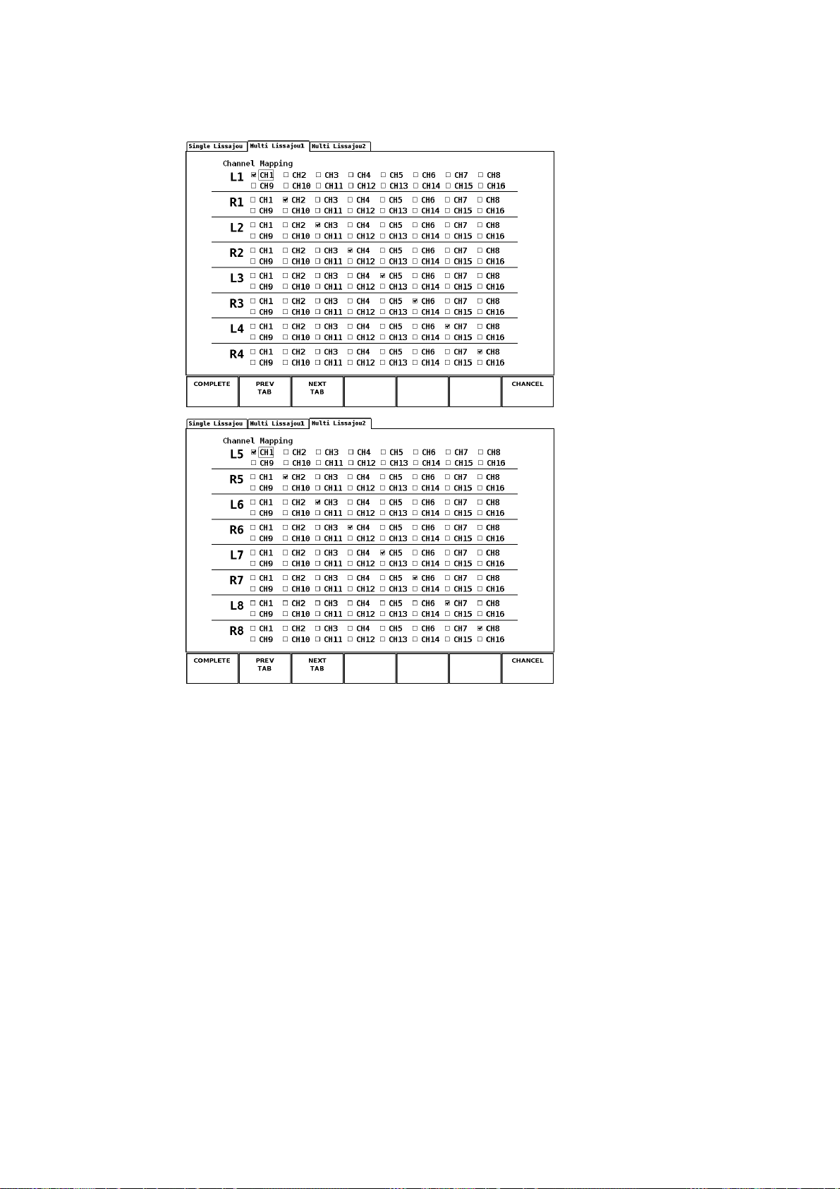
● F•6 CHANNEL MAPPING
Select the channels that you want to map to the L and R axes of the Lissajous
waveform. Turn F•D to select the channel you want to map to the L and R axes
separately, and press F•D to confirm the selection. The selected channels appear at
the bottom of the meter.
There are separate channel mapping screens for single Lissajous and multi Lissajous.
Set them accordingly.
The operations you can carry out on the channel mapping screen are as follows:
F•1 COMPLETE Applies the settings and closes the channel mapping screen.
F•2 PREV TAB Returns to the previous tab screen.
F•3 NEXT TAB Proceeds to the next tab screen.
F•7 CANCEL Closes the channel mapping screen without applying the settings.
The figure below shows the channel mapping screen for the single Lissajous
waveform when the number of measurement channels is 16.
Figure 6-8 Channel mapping screen for the single Lissajous waveform
The down mixing calculations described below is performed on Lt and Rt according to
the channels mapped using F•6 CHANNEL MAPPING in the surround setup menu.
See section 6.2.2, “Configuring the Surround Display”
Lt = 1/√2 ( L + 1/√2 * C + 1/√2 * Ls )
Rt = 1/√2 ( R + 1/√2 * C + 1/√2 * Rs )
34
Page 38
6. MEASUREMENT DISPLAYS
The following figure shows the channel mapping screens for multiple Lissajous
waveforms when the number of measurement channels is 16.
Figure 6-9 Channel mapping screens for multi Lissajous waveforms
35
Page 39

6.2 Surround Display
6.2.1 Surround Display Screen
6. MEASUREMENT DISPLAYS
The surround display shows surround waveforms of channels mapped to the axes.
To display the surround waveform, press AUDIO or UNIT #*, and then press F•2 DISPLAY
MODE to select SURROUND. (The surround waveform cannot be displayed if the number
of measurement channels is 16, if the input signal is analog, or if MIX MODE is ON.)
* Select the unit number in which the LV 58SER40(A) is installed.
Audio menu
Figure 6-10 Audio menu
The left half of the surround display shows the surround waveform, and the right half shows
meters. (Meters are not displayed when the 2-screen display is enabled.)
If adjacent channels (including Lch and Rch for PHANTOM C) are of opposite phases, the
scale between the channels is displayed in red.
Figure 6-11 Surround display
36
Page 40

6. MEASUREMENT DISPLAYS
6.2.2 Configuring the Surround Display
To configure the surround display, press F•4 SURROUND SETUP in the audio menu. F•4
SURROUND SETUP appears when the surround display is showing.
Audio menu
Surround setup menu
Figure 6-12 Surround setup menu
The items in the surround setup menu are described below.
● F•1 SURROUND INTEN
Turn F•D to set the surround waveform intensity. The selectable range is from -128 to
127 (256 levels). Pressing F•D resets the intensity to the default value (100).
● F•2 SCALE INTEN
Set the scale intensity by turning F•D. The selectable range is from -8 to 7 (16 levels).
Pressing F•D resets the intensity to the default value (4).
● F•3 SURROUND 5.1
Select the surround waveform display format from the available settings below.
NORMAL A waveform that combines Lch, Rch, Lsch, Rsch, and Cch (hard
center) is displayed.
PHANTOM C A waveform that combines Lch, Rch, Lsch, Rsch, and phantom center
and a Cch (hard center) waveform are displayed separately.
NORMAL PHANTOM C
Figure 6-13 Surround formats of surround waveforms
37
Page 41

● F•5 AUTO GAIN
6. MEASUREMENT DISPLAYS
Set the surround waveform auto gain control (AGC).
ON Automatically adjusts the gain so that the amplitude of the surround
waveform fits within a given range when the input signal level is from
-25 to 0 dBFS.
OFF Does not automatically adjust the amplitude of the surround waveform.
● F•6 CHANNEL MAPPING
Map the channels to the L, R, C, LFE, Ls, Rs, Lt, and Rt axes of the surround
waveform. Turn F•D to select the channel you want to map to each axis, and press
F•D to confirm the selection. The selected channels appear at the bottom of the meter.
This setting affects the Lt and Rt calculations that are performed when using F•6
CHANNEL MAPPING in the Lissajous setup menu.
The operations you can carry out on the channel mapping screen are as follows:
F•1 COMPLETE Applies the settings and closes the channel mapping screen.
F•7 CANCEL Closes the channel mapping screen without applying the settings.
Figure 6-14 Channel mapping screen for surround waveforms
38
Page 42

6.3 Status Display
6.3.1 Status Display Screen
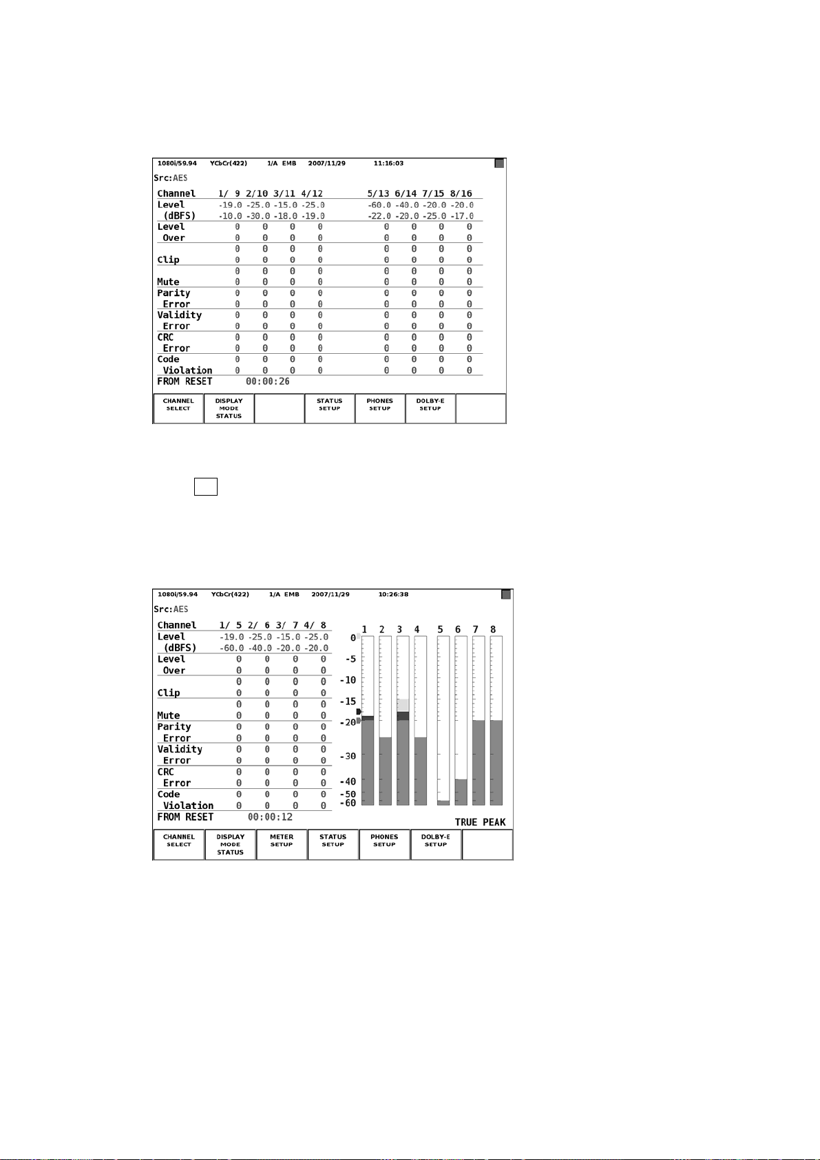
The status screen displays information such as the level, the error count, and the time from
reset for each channel. The top and bottom lines of each status item correspond to the
channel indicated to the left of the slash and that indicated to the right of the slash,
respectively.
To display the status screen, press AUDIO or UNIT #*, and then press F•2 DISPLAY
MODE to select STATUS. (The status screen cannot be displayed if the input signal is
analog.)
* Select the unit number in which the LV 58SER40(A) is installed.
Audio menu
If the number of measurement channels is set to eight (and MIX MODE is not ON), the left
half of the screen displays the status, and the right half displays meters for the eight
channels. (Meters are not displayed when the 2-screen display is enabled.)
See section 7.1, “Selecting Measurement Channels”
6. MEASUREMENT DISPLAYS
Figure 6-15 Audio menu
Figure 6-16 Status screen for eight channels
39
Page 43
6. MEASUREMENT DISPLAYS
If the number of measurement channels is set to 16, the status for 16 channels will be
displayed.
See section 7.1, “Selecting Measurement Channels”
Figure 6-17 16-channel status screen
When F•3 MIX MODE in the channel selection menu is set to ON, the statuses for eight
audio signal channels and for eight Dolby signal channels are displayed on the left and
right sides of the screen, respectively. When INPUT GROUP is a channel group from
CH1/2 to CH7/8, audio signal channels 1 to 8 are displayed. When INPUT GROUP is a
channel group from CH9/10 to CH15/16, audio signal channels 9 to 16 are displayed.
Figure 6-18 MIX MODE status screen
40
Page 44

6. MEASUREMENT DISPLAYS
The items in the status display screen are described below.
The error count is not displayed for any of the following items whose error detection is set
to OFF on the system configuration's unit setup screen.
See section 7.5, “System Configuration”
● Channel
Indicates the channels. For channels delimited by a slash, the channel to the left and
the channel to the right of the slash correspond to the top and bottom lines of each
status item, respectively.
● Level(dBFS)
Indicates the numerical input signal levels. The unit is dBFS. If there is no input, U.L
will be displayed, and the subsequent items will be blank.
● Level Over
This counter is incremented each time the input signal level exceeds the OVER
LEVEL value set using F•6 METER SETTING in the meter setup menu. The maximum
error count is 9999. You can reset the counter back to zero.
See section 6.4.2, “Configuring the Meter Display”
● Clip
This counter is incremented if the maximum input signal occurs consecutively
exceeding the sample count that is specified by the Clip setting in system setup. The
maximum error count is 9999. You can reset the counter back to zero.
See section 7.5, “System Setup”
● Mute
This counter is incremented if the 0x0 input signal occurs continuously exceeding the
time specified by the Mute setting in system setup. The maximum error count is 9999.
You can reset the counter back to zero.
Audio signals that are extracted from DVB-ASI signals are not supported. The error
count will not be displayed for these signals.
See section 7.5, “System Setup”
● Parity Error
This counter is incremented when the input signal parity bit differs from the parity bit
that this unit calculates internally. This counter only handles HD-SDI signals when
measuring audio signals that are embedded in SDI signals. The error count will be
blank if you apply SD-SDI signals. The counter also does not handle audio signals that
are embedded in DVB-ASI signals. The error count will be blank if you apply DVB-ASI
signals. The maximum error count is 9999. You can reset the counter back to zero.
Audio signals that are extracted from SD-SDI or DVB-ASI signals are not supported.
The error count will not be displayed for these signals.
● Validity Error
This counter is incremented when the input signal parity bit is 1. The maximum error
count is 9999. You can reset the counter back to zero.
41
Page 45

6. MEASUREMENT DISPLAYS
● CRC Error
This counter is incremented if the CRC value of the input signal’s channel status bit is
different from the CRC value that this unit calculates internally. The maximum error
count is 9999. You can reset the counter back to zero.
● Code Violation
This counter is incremented when the bi-phase modulation status of the input signal is
determined to be in error. The maximum error count is 9999. You can reset the counter
back to zero.
● FROM RESET
Indicates the time since you pressed F•6 ERROR RESET in the status setup menu.
See section 6.3.2, “Configuring the Status Display”
The following items appear when DECODE MODE is DOLBY-E or DOLBY-DIGITAL.
● Dolby CRC Error
This counter is incremented if the CRC value of the Dolby signal is different from the
CRC value that is calculated internally by the Dolby E option. The maximum error
count is 9999. You can reset the counter back to zero.
● Frame Location
Indicates the location of the header embedded in the SDI input signal and the mode
(16-, 20-, or 24-bit). Does not appear when a slot with the LV 58SER40(A) installed is
selected.
● ch
The channel that INPUT GROUP has been set to appears.
42
Page 46
6. MEASUREMENT DISPLAYS
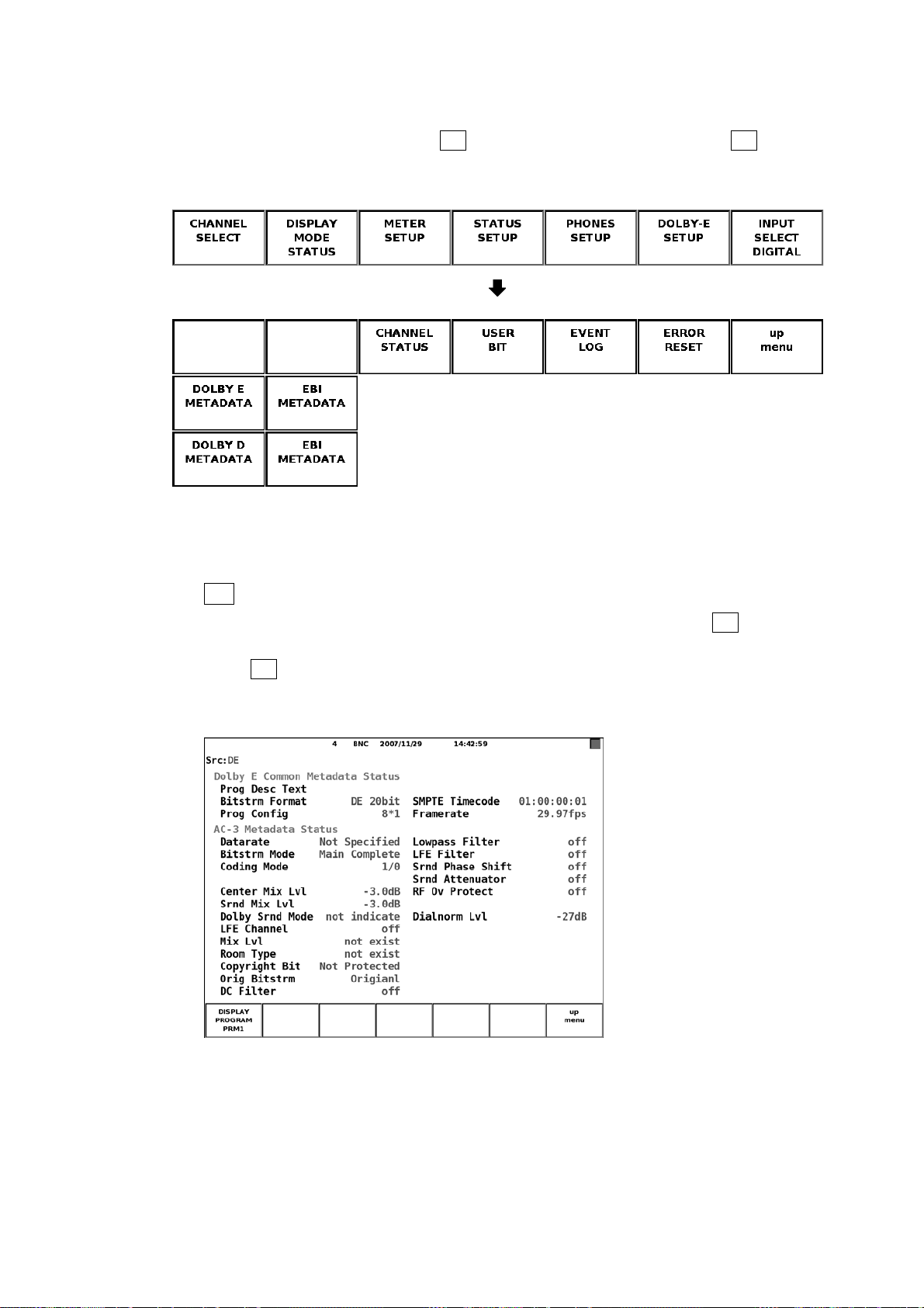
6.3.2 Configuring the Status Display
To configure the status display, press F•4 STATUS SETUP in the audio menu. F•4 STATUS
SETUP appears when the status display is showing.
Audio menu
Status setup menu
Figure 6-19 Status setup menu
The items in the status setup menu are described below.
● F•1 DOLBY E METADATA
This menu appears when you set DECODE MODE to DOLBY-E using F•1 CHANNEL
SETTING in the Dolby setup menu.
Press F•1 DISPLAY PROGRAM to view the metadata of the selected program
number.
See section 7.3, “Dolby Setup”
Figure 6-20 Dolby E signal metadata display
43
Page 47

6. MEASUREMENT DISPLAYS
The Dolby E signal metadata display is described below.
• Prog Desc Text
Displays up to 32 characters of the text data corresponding to the program number
that you select using F•1 DISPLAY PROGRAM in the status setup menu.
• Bitstrm Format
Displays the input signal format.
Table 6-1 Bitstrm Format display
Retrieved value Displayed information
0 DD 32bit
1 DD 16bit Ch1
2 DD 16bit Ch2
3 DD 16bit Ch1/2
4 DE 24bit
5 DE 20bit
6 DE 16bit
7 PCM
• Prog Config
Displays the input signal program configuration.
Table 6-2 Prog Config display
Retrieved value Displayed information
0 5.1+2
1 5.1+2*1
2 4+4
3 4+2*2
4 4+2+2*1
5 4+4*1
6 4*2
7 3*2+2*1
8 2*2+4*1
9 2+6*1
10 8*1
11 5.1
12 4+2
13 4+2*1
14 3*2
15 2*2+2*1
16 2+4*1
17 6*1
18 4
19 2+2
20 2+2*1
21 4*1
44
Page 48

6. MEASUREMENT DISPLAYS
Retrieved value Displayed information
22 7.1
23 7.1Screen
Other values not define
• SMPTE Timecode
Displays the input signal SMPTE time code.
• Framerate
Displays the input signal frame rate.
Table 6-3 Framerate display
Retrieved value Displayed information
0 reserved
1 23.98fps
2 24fps
3 25fps
4 29.97fps
5 30fps
6 50fps
7 59.94fps
8 60fps
9 unknown
Other values not define
• Datarate
Displays the data rate information in the Dolby Digital metadata embedded in the input
signal.
Table 6-4 Datarate display
Retrieved value Displayed information
0 32kbps
1 40kbps
2 48kbps
3 56kbps
4 64kbps
5 80kbps
6 96kbps
7 112kbps
8 128kbps
9 160kbps
10 192kbps
11 224kbps
12 256kbps
13 320kbps
14 384kbps
45
Page 49

6. MEASUREMENT DISPLAYS
Retrieved value Displayed information
15 448kbps
16 512kbps
17 576kbps
18 640kbps
19 to 30 reserved
31 Not Specified
Other values not define
• Bitstrm Mode
Displays the bitstream mode information in the Dolby Digital metadata embedded in
the input signal.
Table 6-5 Bitstrm Mode display
Retrieved value Displayed information
0 Main Complete
1 Music and Effects
2 Visually Inpaired
3 Hearing Impaired
4 Dialogue
5 Commentary
6 Emergency
7
Other values not define
reserved (when coding mode = 0)
Voice Over (when coding mode = 1)
Karaoke (when coding mode > 1)
• Coding Mode
Displays the coding mode information in the Dolby Digital metadata embedded in the
input signal.
Table 6-6 Coding Mode display
Retrieved value Displayed information
0 reserved
1 1/0
2 2/0
3 3/0
4 2/1
5 3/1
6 2/2
7 3/2
Other values not define
46
Page 50

6. MEASUREMENT DISPLAYS
• Center Mix Lvl
Displays the center mix level information in the Dolby Digital metadata embedded in
the input signal.
Table 6-7 Center Mix Lvl display
Retrieved value Displayed information
0 -3.0dB
1 -4.5dB
2 -6.0dB
Other values not define
• Srnd Mix Lvl
Displays the surround mix level information in the Dolby Digital metadata embedded in
the input signal.
Table 6-8 Srnd Mix Lvl display
Retrieved value Displayed information
0 -3.0dB
1 -6.0dB
2 -∞dB
Other values not define
• Dolby Srnd Mode
Displays the Dolby surround mode information in the Dolby Digital metadata
embedded in the input signal.
Table 6-9 Dolby Srnd Mode display
Retrieved value Displayed information
0 not indicate
1 off
2 on
Other values not define
• LFE Channel
Displays the LFE channel information in the Dolby Digital metadata embedded in the
input signal.
Table 6-10 LFE Channel display
Retrieved value Displayed information
0 off
1 on
Other values not define
47
Page 51

6. MEASUREMENT DISPLAYS
• Mix Lvl
Displays the mix level information in the Dolby Digital metadata embedded in the input
signal.
Table 6-11 Mix Lvl display
AC-3* Retrieved value Displayed information
0 - not exist
1 0 to 31 Level obtained by adding the retrieved
value to 80 dB
* AC-3 Audio Production Information Exists(0x0B)
• Room Type
Displays the room type information in the Dolby Digital metadata embedded in the
input signal.
Table 6-12 Room Type display
AC-3* Retrieved value Displayed information
0 - not exist
1
* AC-3 Audio Production Information Exists(0x0B)
0 not indicate
1 Large Room
2 Small Room
Other values not define
• Copyright Bit
Displays the copyright bit in the Dolby Digital metadata embedded in the input signal.
Table 6-13 Copyright Bit display
Retrieved value Displayed information
0 Not Protected
1 Protected
Other values not define
• Orig Bitstrm
Displays the original bitstream information in the Dolby Digital metadata embedded in
the input signal.
Table 6-14 Orig Bitstrm display
Retrieved value Displayed information
0 Not Original
1 Original
Other values not define
48
Page 52

6. MEASUREMENT DISPLAYS
• DC Filter
Displays the DC highpass filter enable information in the Dolby Digital metadata
embedded in the input signal.
Table 6-15 DC Filter display
Retrieved value Displayed information
0 off
1 on
Other values not define
• Lowpass Filter
Displays the bandwidth lowpass filter enable information in the Dolby Digital metadata
embedded in the input signal.
Table 6-16 Lowpass Filter display
Retrieved value Displayed information
0 off
1 on
Other values not define
• LFE Filter
Displays the LFE channel lowpass filter enable information in the Dolby Digital
metadata embedded in the input signal.
Table 6-17 LFE Filter display
Retrieved value Displayed information
0 off
1 on
Other values not define
• Srnd Phase Shift
Displays the surround 90degree phase shift filter enable information in the Dolby
Digital metadata embedded in the input signal.
Table 6-18 Srnd Phase Shift display
Retrieved value Displayed information
0 off
1 on
Other values not define
49
Page 53

6. MEASUREMENT DISPLAYS
• Srnd Attenuator
Displays the surround channel attenuator enable information in the Dolby Digital
metadata embedded in the input signal.
Table 6-19 Srnd Attenuator display
Retrieved value Displayed information
0 off
1 on
Other values not define
• RF Ov Protect
Displays the RF overmodulation protect enable information in the Dolby Digital
metadata embedded in the input signal.
Table 6-20 RF Ov Protect display
Retrieved value Displayed information
0 off
1 on
Other values not define
• Dialnorm Lvl
Displays the dialog normalization level information in the Dolby Digital metadata
embedded in the input signal.
Table 6-21 Dialnorm Lvl display
Retrieved value Displayed information
1 to 31 Level obtained by adding a minus sign to
the retrieved value
50
Page 54
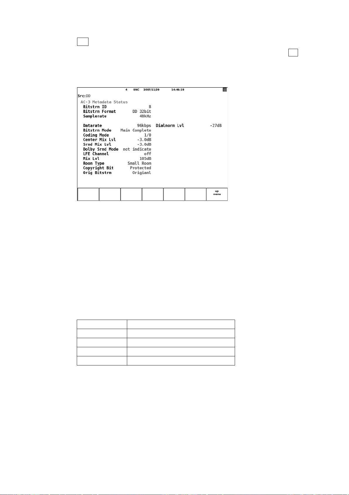
6. MEASUREMENT DISPLAYS
● F•1 DOLBY D METADATA
This menu appears when you set DECODE MODE to DOLBY-DIGITAL using F•1
CHANNEL SETTING in the Dolby setup menu.
You can view the Dolby Digital signal metadata.
See section 7.3, “Dolby Setup”
Figure 6-21 Dolby Digital signal metadata display
The Dolby Digital signal metadata display is described below.
• Bitstrm ID
Displays the input signal ID.
• Bitstrm Format
Displays the input signal format (see Table 6-1).
• Samplerate
Displays the input signal sample rate.
Table 6-22 Samplerate display
Retrieved value Displayed information
0 48kHz
1 44.1kHz
2 32kHz
Other values not define
• Datarate
Displays the input data rate (see Table 6-4).
• Bitstrm Mode
Displays the input signal bitstream mode (see Table 6-5).
51
Page 55

• Coding Mode
6. MEASUREMENT DISPLAYS
Displays the input signal coding mode.
Table 6-23 Coding Mode display
Retrieved value Displayed information
0 1+1
1 1/0
2 2/0
3 3/0
4 2/1
5 3/1
6 2/2
7 3/2
Other values not define
• Center Mix Lvl
Displays the input signal center mix level (see Table 6-7).
• Srnd Mix Lvl
Displays the input signal surround mix level (see Table 6-8).
• Dolby Srnd Mode
Displays the input signal Dolby surround mode (see Table 6-9).
• LFE Channel
Displays the input signal LFE channel (see Table 6-10).
• Mix Lvl
Displays the input signal mix level.
Table 6-24 Mix Lvl display
Dolby D* Retrieved value Displayed information
0 - not exist
1 0 to 31 Level obtained by adding the retrieved
value to 80 dB
* Dolby Digital Audio Protection Information Exists (0x0C)
• Room Type
Displays the input signal room type (see Table 6-12).
Table 6-25 Room Type display
Dolby D* Retrieved value Displayed information
0 - not exist
1
* Dolby Digital Audio Production Information Exists(0x0C)
0 not indicate
1 Large Room
2 Small Room
Other values not define
52
Page 56
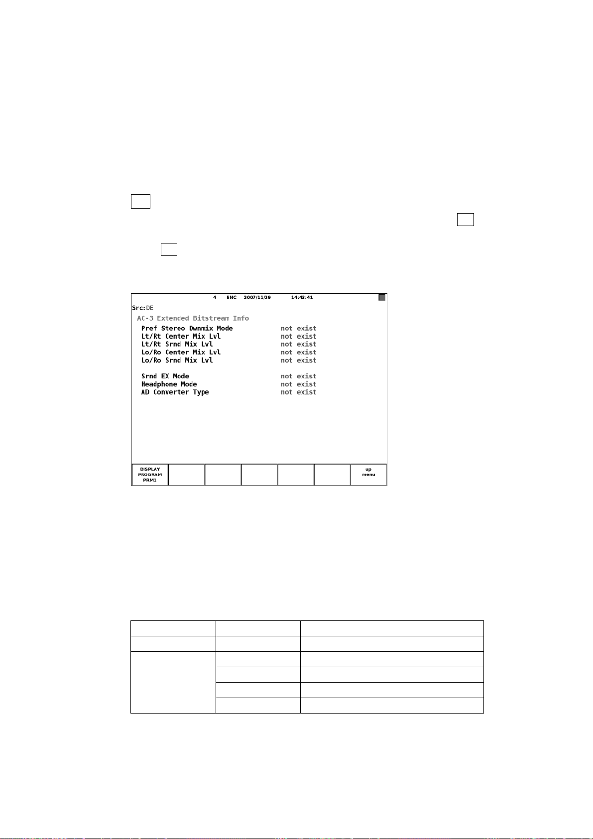
• Copyright Bit
6. MEASUREMENT DISPLAYS
Displays the input signal copyright bit (see Table 6-13).
• Orig Bitstrm
Displays the input signal original bitstream (see Table 6-14).
• Dialnorm Lvl
Displays the input signal dialog normalization level (see Table 6-21).
● F•2 EBI METADATA (when the input signal is Dolby E)
This menu appears when you set DECODE MODE to DOLBY-E using F•1 CHANNEL
SETTING in the Dolby setup menu.
Press F•1 DISPLAY PROGRAM to view the extended bitstream info (EBI) metadata of
the selected program number.
See section 7.3, “Dolby Setup”
Figure 6-22 Dolby E signal EBI metadata display
The Dolby E signal EBI metadata display is described below.
• Pref Stereo Dwnmix Mode
Displays the extended preferred stereo downmix mode information in the Dolby Digital
metadata embedded in the input signal.
Table 6-26 Pref Stereo Dwnmix Mode display
AC-3* Retrieved value Displayed information
0 - not exist
1
* AC-3 Extended Bitstream Information1 Exsists(0x10)
0 not indicate
1 Lt/Rt Preferred
2 Lo/Ro Preferred
Other values not define
53
Page 57

6. MEASUREMENT DISPLAYS
• Lt/Rt Center Mix Lvl
Displays the Lt/Rt center mix level information in the Dolby Digital metadata embedded
in the input signal.
Table 6-27 Lt/Rt Center Mix Lvl display
AC-3* Retrieved value Displayed information
0 - not exist
1
* AC-3 Extended Bitstream Information1 Exsists(0x10)
0 +3.0dB
1 +1.5dB
2 0.0dB
3 -1.5dB
4 -3.0dB
5 -4.5dB
6 -6.0dB
7 -∞dB
Other values not define
• Lt/Rt Srnd Mix Lvl
Displays the Lt/Rt surround mix level information in the Dolby Digital metadata
embedded in the input signal.
Table 6-28 Lt/Rt Srnd Mix Lvl display
AC-3* Retrieved value Displayed information
0 - not exist
1
* AC-3 Extended Bitstream Information1 Exsists(0x10)
0 +3.0dB
1 +1.5dB
2 0.0dB
3 -1.5dB
4 -3.0dB
5 -4.5dB
6 -6.0dB
7 -∞dB
Other values not define
54
Page 58

6. MEASUREMENT DISPLAYS
• Lo/Ro Center Mix Lvl
Displays the Lo/Ro center mix level information in the Dolby Digital metadata
embedded in the input signal.
Table 6-29 Lo/Ro Center Mix Lvl display
AC-3* Retrieved value Displayed information
0 - not exist
1
* AC-3 Extended Bitstream Information1 Exsists(0x10)
0 +3.0dB
1 +1.5dB
2 0.0dB
3 -1.5dB
4 -3.0dB
5 -4.5dB
6 -6.0dB
7 -∞dB
Other values not define
• Lo/Ro Srnd Mix Lvl
Displays the Lo/Ro surround mix level information in the Dolby Digital metadata
embedded in the input signal.
Table 6-30 Lo/Ro Srnd Mix Lvl display
AC-3* Retrieved value Displayed information
0 - not exist
1
* AC-3 Extended Bitstream Information1 Exsists(0x10)
0 +3.0dB
1 +1.5dB
2 0.0dB
3 -1.5dB
4 -3.0dB
5 -4.5dB
6 -6.0dB
7 -∞dB
Other values not define
55
Page 59

6. MEASUREMENT DISPLAYS
• Srnd EX Mode
Displays the Surround EX Mode information in the Dolby Digital metadata embedded
in the input signal.
Table 6-31 Srnd EX Mode display
AC-3* Retrieved value Displayed information
0 - not exist
1
* AC-3 Extended Bitstream Information2 Exsists(0x16)
0 not indicate
1 off
2 on
Other values not define
• Headphone Mode
Displays the Headphone Mode information in the Dolby Digital metadata embedded in
the input signal.
Table 6-32 Headphone Mode display
AC-3* Retrieved value Displayed information
0 - not exist
1 - not define
* AC-3 Extended Bitstream Information2 Exsists(0x16)
• AD Converter Type
Displays the AD Converter Type information in the Dolby Digital metadata embedded
in the input signal.
Table 6-33 AD Converter Type display
AC-3* Retrieved value Displayed information
0 - not exist
1
* AC-3 Extended Bitstream Information2 Exsists(0x16)
0 standard
1 HDCD
Other values not define
56
Page 60

6. MEASUREMENT DISPLAYS
● F•2 EBI METADATA (when the input signal is Dolby Digital)
This menu appears when you set DECODE MODE to DOLBY-DIGITAL using F•1
CHANNEL SETTING in the Dolby setup menu.
You can view the Dolby Digital signal extended bitstream info (EBI) metadata.
See section 7.3, “Dolby Setup”
Figure 6-23 Dolby Digital signal EBI metadata display
The Dolby Digital signal EBI metadata display is described below.
• Pref Stereo Dwnmix Mode
Displays the input signal extended preferred stereo downmix mode.
Table 6-34 Pref Stereo Dwnmix Mode display
Dolby D* Retrieved value Displayed information
0 - not exist
1
* Dolby Digital Extended Bitstream Information1 Exists(0x11)
0 not indicate
1 Lt/Rt Preferred
2 Lo/Ro Preferred
Other values not define
57
Page 61
• Lt/Rt Center Mix Lvl
6. MEASUREMENT DISPLAYS
Displays the input signal Lt/Rt center mix level.
Table 6-35 Lt/Rt Center Mix Lvl display
Dolby D* Retrieved value Displayed information
0 - not exist
1
* Dolby Digital Extended Bitstream Information1 Exists(0x11)
0 +3.0dB
1 +1.5dB
2 0.0dB
3 -1.5dB
4 -3.0dB
5 -4.5dB
6 -6.0dB
7 -∞dB
Other values not define
• Lt/Rt Srnd Mix Lvl
Displays the input signal Lt/Rt surround mix level.
Table 6-36 Lt/Rt Srnd Mix Lvl display
Dolby D* Retrieved value Displayed information
0 - not exist
1
* Dolby Digital Extended Bitstream Information1 Exists(0x11)
0 +3.0dB
1 +1.5dB
2 0.0dB
3 -1.5dB
4 -3.0dB
5 -4.5dB
6 -6.0dB
7 -∞dB
Other values not define
58
Page 62

• Lo/Ro Center Mix Lvl
6. MEASUREMENT DISPLAYS
Displays the input signal Lo/Ro center mix level.
Table 6-37 Lo/Ro Center Mix Lvl display
Dolby D* Retrieved value Displayed information
0 - not exist
1
* Dolby Digital Extended Bitstream Information1 Exists(0x11)
0 +3.0dB
1 +1.5dB
2 0.0dB
3 -1.5dB
4 -3.0dB
5 -4.5dB
6 -6.0dB
7 -∞dB
Other values not define
• Lo/Ro Srnd Mix Lvl
Displays the input signal Lo/Ro surround mix level.
Table 6-38 Lo/Ro Srnd Mix Lvl display
Dolby D* Retrieved value Displayed information
0 - not exist
1
* Dolby Digital Extended Bitstream Information1 Exists(0x11)
0 +3.0dB
1 +1.5dB
2 0.0dB
3 -1.5dB
4 -3.0dB
5 -4.5dB
6 -6.0dB
7 -∞dB
Other values not define
59
Page 63

• Srnd EX Mode
6. MEASUREMENT DISPLAYS
Displays the input signal Surround EX Mode.
Table 6-39 Srnd EX Mode display
Dolby D* Retrieved value Displayed information
0 - not exist
1
* Dolby Digital Extended Bitstream Information2 Exists(0x17)
0 not indicate
1 off
2 on
Other values not define
• Headphone Mode
Displays the input signal Headphone Mode.
Table 6-40 Headphone Mode display
Dolby D* Retrieved value Displayed information
0 - not exist
1 - not define
* Dolby Digital Extended Bitstream Information2 Exists(0x17)
• AD Converter Type
Displays the input AD Converter Type.
Table 6-41 AD Converter Type display
Dolby D* Retrieved value Displayed information
0 - not exist
1
* Dolby Digital Extended Bitstream Information2 Exists(0x17)
0 standard
1 HDCD
Other values not define
60
Page 64

6. MEASUREMENT DISPLAYS
● F•3 CHANNEL STATUS
Press F•1 DISPLAY CHANNEL to view the metadata of the selected channel. Press
F•2 ALIGN to select whether to display LSB first or MSB first.
Figure 6-24 Channel status display
The items in the channel status display are described below.
• FORMAT
Displays the input signal type.
Table 6-42 FORMAT display
Byte Bit Retrieved value Displayed information
0 Consumer 00 0
1 Professional
• AUDIO DATA
Displays the input signal receive mode.
Table 6-43 AUDIO display
Byte Bit Retrieved value Displayed information
0 PCM 00 1
1 No-PCM
61
Page 65

• EMPHASIS
6. MEASUREMENT DISPLAYS
Displays the input signal emphasis mode.
Table 6-44 EMPHASIS display
Byte Bit Retrieved value Displayed information
00 4..2
000 Not indicated
001 No emphasis
011 50/15-us
111 C C I T T J.17
Other values Reserved
• SIGNAL LOCK
Displays the input signal lock status.
Table 6-45 SIGNAL LOCK display
Byte Bit Retrieved value Displayed information
0 Locked 00 5
1 unlocked
• SAMPLING FREQ
Displays the input signal sampling frequency.
Table 6-46 SAMPLING FREQ display 1
Byte Bit Retrieved
value
00 7..6
00 - - - See Table 6-47.
Byte Bit Retrieved
value
0 48kHz 10 04 7
1 48kHz/1.001
0 44.1kHz 01 04 7
1 44.1kHz/1.001
0 32kHz 11 04 7
1 32kHz/1.001
Displayed information
62
Page 66
6. MEASUREMENT DISPLAYS
Table 6-47 SAMPLING FREQ display 2
Byte Bit Retrieved
value
04 7..3
0000 - - - Not indicated
0100 to
1000
1100 to
1110
1111 - - - User defined
Byte Bit Retrieved
value
0 24kHz 0001 04 7
1 24kHz/1.001
0 96kHz 0010 04 7
1 96kHz/1.001
0 192kHz 0011 04 7
1 192kHz/1.001
- - - Reserved
0 22.05kHz 1001 04 7
1 22.05kHz/1.001
0 88.2kHz 1010 04 7
1 88.2kHz/1.001
0 176.4kHz 1011 04 7
1 176.4kHz/1.001
- - - Reserved
Displayed information
• REFERENCE
Displays the input signal reference mode.
Table 6-48 REFERENCE display
Byte Bit Retrieved value Displayed information
04 1..0
00 Not reference
10 Grade1
01 Grade2
11 Reserved
63
Page 67

• CH MODE
6. MEASUREMENT DISPLAYS
Displays the input signal channel mode.
Table 6-49 CH MODE display
Byte Bit Retrieved value Displayed information
01 3..0
0000 Not indicated
1000 Two-channel
0100 Single-channel
1100 Primary/secondary
0010 Stereophonic
0110 to 1010 User defined
1110 Double sampling
0001 Double sampling - stereo left
1001 Double sampling - stereo right
1111 M u l ti-cha n n el
Other values Reserved
• RESOLUTION
Displays the input signal bit resolution.
Table 6-50 RESOLUTION display 1
Byte Bit Retrieved value Displayed information
02 2..0
000
010
100 See Table 6-52.
Other values User defined
See Table 6-51.
Table 6-51 RESOLUTION display 2
Byte Bit Retrieved value Displayed information
02 5..3
000 Not indicated
100 19bits
010 18bits
110 17bits
001 16bits
101 20bits
Other values Reserved
64
Page 68

6. MEASUREMENT DISPLAYS
Table 6-52 RESOLUTION display 3
Byte Bit Retrieved value Displayed information
02 5..3
000 Not indicated
100 23bits
010 22bits
110 21bits
001 20bits
101 24bits
Other values Reserved
• ALIGNMENT
Displays the input signal alignment level.
Table 6-53 ALIGNMENT display
Byte Bit Retrieved value Displayed information
02 7..6
00 Not indicated
10 SMPTE RP155
01 EBU R68
11 Reserved
• ORIGIN
Display bytes 06 to 09 in the input signal in ASCII code.
• DESTINATION
Display bytes 10 to 13 in the input signal in ASCII code.
• TIME-OF-DAY
Display bytes 18 to 21 in the input signal converted to time.
• CRC
Displays “NORMAL” when the input signal channel status bit’s CRC value and the
CRC value that the LV 58SER40 calculates match. Displays “ERROR” otherwise.
65
Page 69
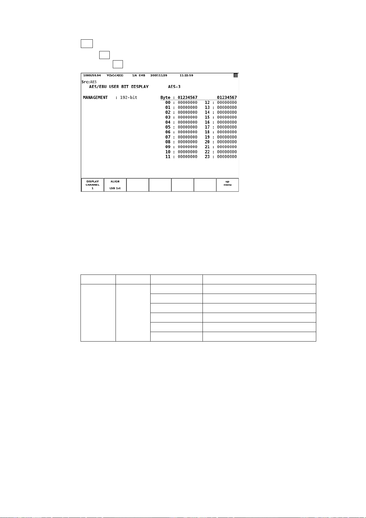
6. MEASUREMENT DISPLAYS
● F•4 USER BIT
Press F•1 DISPLAY CHANNEL to view the metadata of the selected channel’s user
bits. Press F•2 ALIGN to select whether to display LSB first or MSB first.
Figure 6-25 User bit display
The user bit display is described below.
• MANAGEMENT
Retrieves the input signal encoding information from the channel status and displays
it.
Table 6-54 MANAGEMENT display
Byte* Bit* Retrieved value Displayed information
01 7..4
* The byte and bit in the channel status display.
0000 Not indicated
1000 192-bit
0100 AES18
1100 User defined
0010 IEC60958-3
Other values Reserved
66
Page 70

6. MEASUREMENT DISPLAYS
● F•5 EVENT LOG (LV 58SER40A only)
You can display a list of the events that have occurred on the installed units.
As an example, the following figure shows the event log when an LV 58SER01A (SDI
INPUT) is installed in slot 1, an LV 58SER06 (3G-SDI INPUT) is installed in slot 2, and
an LV 58SER40A is installed in slot 3.
Figure 6-26 Event log
• Event log explanation
Events are listed in the event log by the time of their occurrence.
By turning the F•D to the right, you can scroll the screen to view older events in the log.
Also, by pressing the F•D, you can display the latest events in the log.
This unit records events related to audio signals extracted from SDI or DVB-ASI
signals and events related to audio signals received through the rear panel BNC
connector. For the former, the format of the audio signal is displayed. For the latter,
“BNC” is displayed.
Regardless of which signal is recorded, the event log displays the unit number that this
unit is installed in.
• Display example of an event related to an audio signal extracted from an SDI or
DVB-ASI signal
The audio signal format is displayed.
• Display example of an event related to an audio signal received through the rear
panel BNC connector
“BNC” is displayed.
67
Page 71
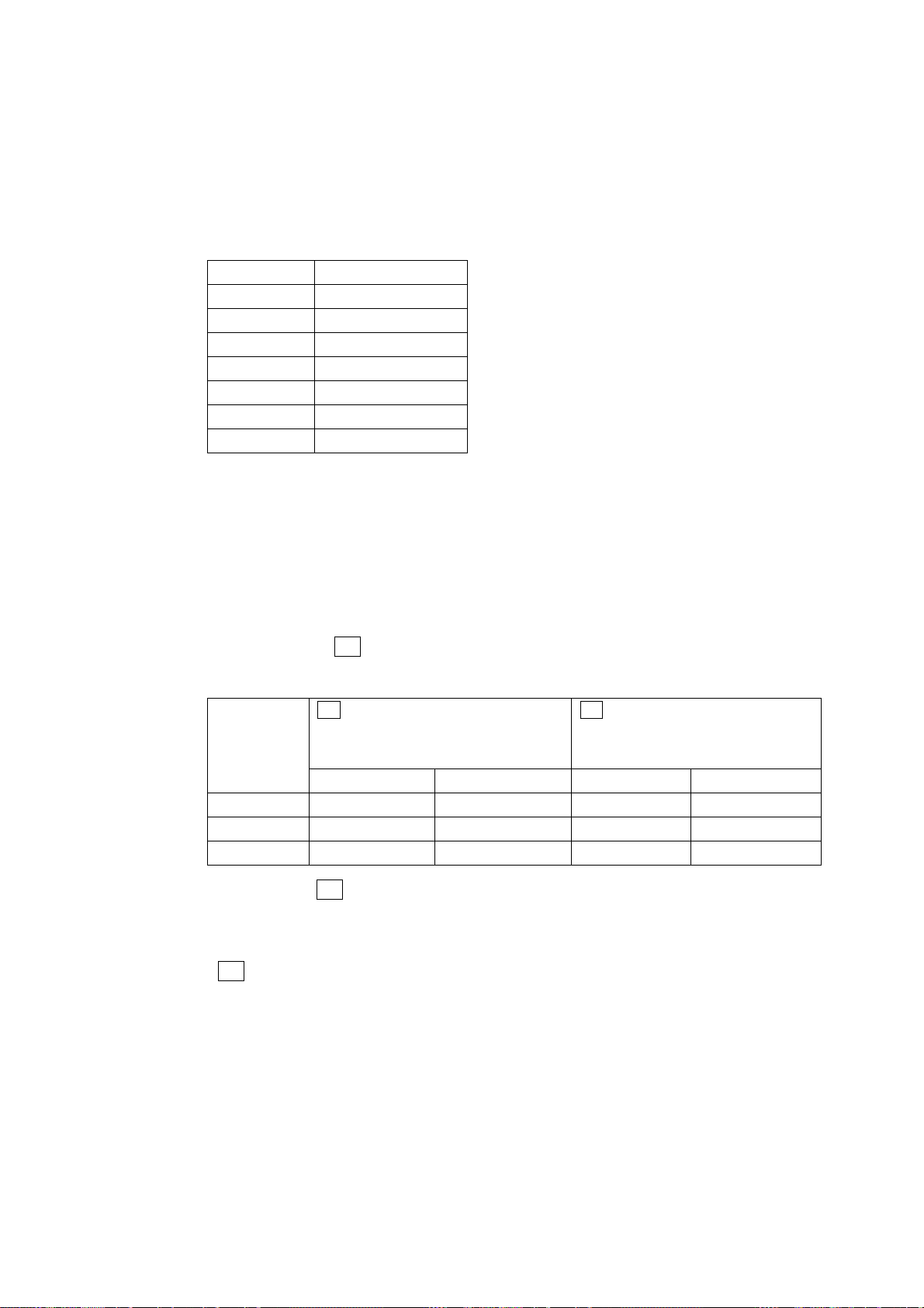
6. MEASUREMENT DISPLAYS
• Event display
The events that are displayed in the event log are listed below.
Of the events listed below, only the events whose detection has been set to ON on the
system configuration's unit setup screen are displayed.
See section 7.5, “System Setup”
Table 6-55 Events
Event Name Description
OVER Level over error
CLIP Clip error
MUTE Mute error
PAR Parity error
VAL Validity error
CRC CRC error
CODE Code violation error
• Channel display
After the event name, the channels on which the event occurred are displayed using a
hexadecimal number (for example: “MUTE:0C”). The channels are displayed in one
byte (for 8 channels) or two bytes (for 16 channels) as necessary according to the
number of measurement channels.
The channels that are displayed using a hexadecimal number vary as shown below
depending on the F•2 DISPLAY MODE setting.
Table 6-56 Channel display
F•2 DISPLAY MODE Is Set to
Measurement
Channels
1 to 8 ch 1ch 8ch L1 R4
9 to 16 ch 9ch 16ch L5 R8
1 to 16 ch 1ch 16ch L1 R8
SURROUND, STATUS, METER (1- or
4-screen display), or LOUDNESS
LSB MSB LSB MSB
F•2 DISPLAY MODE Is Set to
LISSAJOU or METER (2-screen
display)
For example, if F•2 DISPLAY MODE is set to SURROUND and you are performing
measurements on channels 1 to 8, the value 0C (00001100) indicates that events
occurred on channels 3 and 4.
If F•2 DISPLAY MODE is set to LISSAJOU and you are performing measurements on
channels 9 to 16, the value 0C (00001100) indicates that events occurred on the
channels mapped to L6 and R6. Use the channel mapping screen to map channels to
L1 to R8.
For details on the channel mapping screen, see section 6.1.2, “Configuring the Lissajous Display.”
68
Page 72

• Precautions
6. MEASUREMENT DISPLAYS
Even if multiple units are installed on the LV 5800, there is only one log file.
When the same event occurs successively and when multiple events occur at the
same time, they are treated as a single event.
When multiple events occur at the same time, you may not be able to check all of the
events on the screen. When this happens, you can view all of the events by saving
them to USB memory.
The event display is cleared when you initialize the system settings or turn the power
on and off.
Switching video formats or input channels may cause disturbances in the signal that
will cause errors to be displayed.
• Starting Event Logging
Set F•2 LOG to START. “NOW LOGGING” is displayed in the upper right of the screen,
and the event log starts. To stop the event log, set F•2 LOG to STOP.
• Clearing the Event Log
Press F•3 CLEAR to clear the event log.
• Selecting the Overwrite Mode
Press F•4 LOG MODE to select the action to perform when more than 5000 events
occur.
OVER WR When more than 5000 events occur, the LV 5800 writes over older
events.
STOP Events after the 5000th event are not logged.
69
Page 73

6. MEASUREMENT DISPLAYS
• Saving to USB Memory
You can save the event log to USB memory as a text file.
To do so, follow the procedure shown below.
1. Connect a USB memory device to the USB port.
2. Press F•6 USB MEMORY.
The file list display appears.
This menu item appears when USB memory is connected.
Figure 6-27 File list display
3. Press F•1 NAME INPUT.
The file name input display appears.
Figure 6-28 File name input display
70
Page 74

6. MEASUREMENT DISPLAYS
4. Enter a file name using up to 20 characters.
The key operations on the file name input display are explained below.
Spaces are invalid. The spaces that you enter are ignored.
F•1 CLEAR ALL : Deletes all characters.
F•2 DELETE : Deletes the character at the cursor position.
F•3 INSERT : Inserts an underscore (_) at the cursor position.
F•4 <= : Moves the cursor to the left.
F•5 => : Moves the cursor to the right.
F•6 CHAR SET : Enters the selected character.
F•D : Turn to select a character, and press to enter the character.
You can copy the file name of an already saved file. To copy a file name, move the
cursor to the file in the file list whose name you want to copy, and then press the F•D. If
F•5 FILENAME AUTO INC is set to ON, a two-digit number will automatically be
added to the end of the copied file name.
5. Press F•7 up menu.
6. Press F•2 STORE.
When the message “Saving file - Please wait.” disappears, the file has been
successfully saved.
If there is more than one file with the same name in the USB memory, an overwrite
confirmation menu appears. If you want to overwrite the current file, press F•1 OVER
WR YES. Otherwise, press F•3 OVER WR NO.
Deleting an Event Log
To delete an event log that has been saved to USB memory, select the log file in the
file list display, and then press F•4 FILE DELETE. To delete the file, press F•1
DELETE YES. To cancel the delete operation, press F•3 DELETE NO.
Setting File Numbering
When you set F•5 FILENAME AUTO INC in the file list display to ON, a two-digit
number is automatically added to the entered file name (starting with 00). The default
setting is OFF.
This number returns to 00 if you initialize the settings or turn the power on and off.
USB Memory Folder Structure
Event logs are saved in the LOG folder. If there is no LOG folder in the USB memory,
the LV 5800/7800 will create a folder automatically.
USB memory
LOG
└
└
****.TXT
● F•6 ERROR RESET
Resets the error in the status display to zero.
71
Page 75

6.4 Meter Display
6.4.1 Meter Display Screen
6. MEASUREMENT DISPLAYS
The meter screen displays the input signal level and peak hold.1
2
To display the meter screen, press AUDIO or UNIT #
, and then press F•2 DISPLAY
MODE to select METER.
If the number of measurement channels is set to eight (and MIX MODE is not ON) or the
input signal is analog and the 1- or 4-screen display is enabled, the right half of the screen
displays meters at all times.
1 Peak hold levels are only displayed when you set F•2 RESPONSE in the meter setup menu to VU+*.
2 Select the unit number in which the LV 58SER40(A) is installed.
Audio menu
Figure 6-29 Audio menu
If the number of measurement channels is eight (and MIX MODE is not ON) and F•2
DISPLAY MODE is set to LISSAJOU or SURROUND, the meters for the channels that
were mapped on the channel mapping screen will appear. The mapped channels are
displayed below the meter.
If F•2 DISPLAY MODE is set to METER on the 2-screen display, the meters for the
channels that were mapped on the Lissajous display’s channel mapping screen will
appear.
Figure 6-30 Lissajous display for eight channels
72
Page 76

6. MEASUREMENT DISPLAYS
If the number of measurement channels is eight (and MIX MODE is not ON) and F•2
DISPLAY MODE is set to STATUS, the meters for the channels that are set using F•2
DISPLAY CHANNELS in the channel selection menu will appear.
Figure 6-31 Status screen for eight channels
If the number of measurement channels is set to 16, the meters for 16 channels will be
displayed.
Figure 6-32 Meter display for 16 channels
73
Page 77
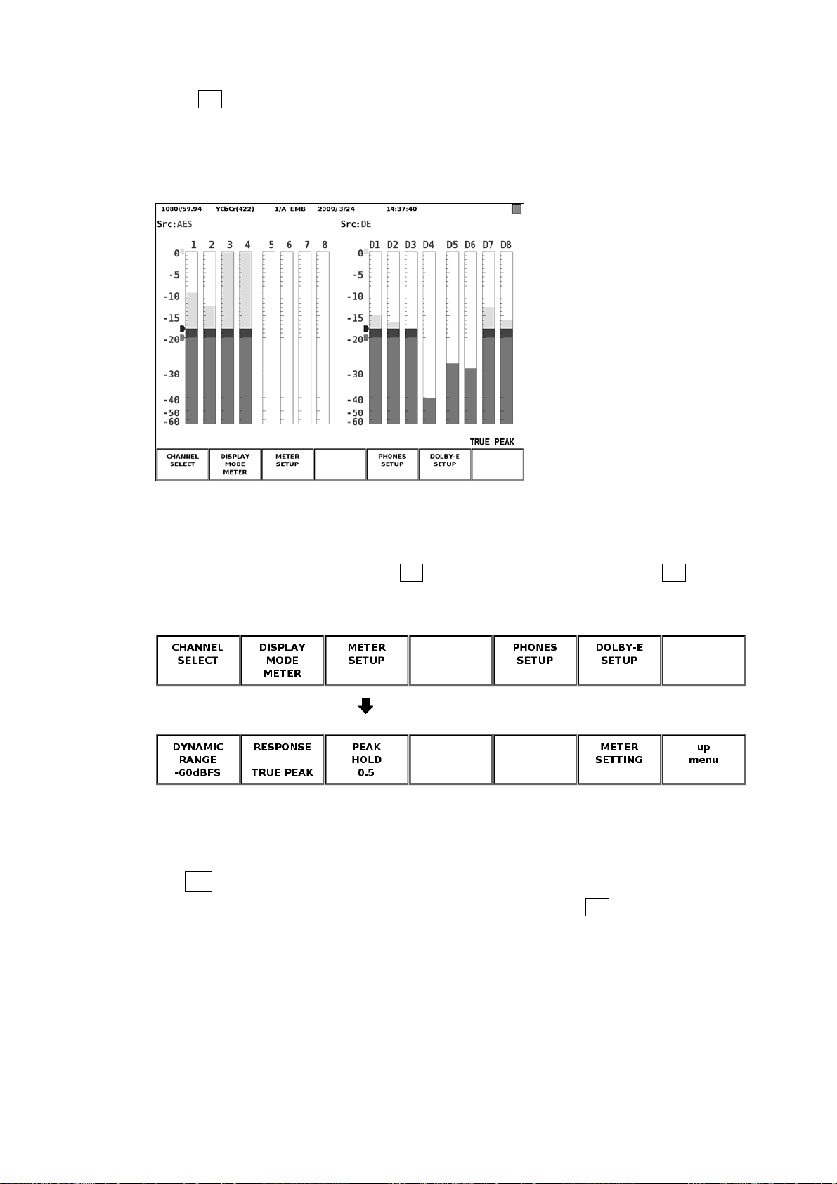
6. MEASUREMENT DISPLAYS
When F•3 MIX MODE in the channel selection menu is set to ON, the meters for eight
audio signal channels and for eight Dolby signal channels are displayed on the left and
right sides of the screen, respectively. When INPUT GROUP is a channel group from
CH1/2 to CH7/8, audio signal channels 1 to 8 are displayed. When INPUT GROUP is a
channel group from CH9/10 to CH15/16, audio signal channels 9 to 16 are displayed.
Figure 6-33 MIX MODE meter display
6.4.2 Configuring the Meter Display
To configure the meter display, press F•3 METER SETUP in the audio menu. F•3 METER
SETUP appears when the meter display is showing.
Audio menu
Meter setup menu
Figure 6-34 Meter setup menu
The items in the meter setup menu are described below.
● F•1 DYNAMIC RANGE
Select the scale of the meter from available settings below. If F•7 INPUT SELECT in
the audio menu is set to ANALOG, the meter scale is fixed at -60dBFS.
-60dBFS Sets the meter scale to 0 to -60 dBFS.
-90dBFS Sets the meter scale to 0 to -90 dBFS.
M A G The meter's scale is set to the meter setting screen's REF LEVEL ± 3
dB. However, this is not applied to the chart display or the loudness
meter on the loudness display. The meter will be set to -60dBFS (LV
58SER40A only).
74
Page 78

6. MEASUREMENT DISPLAYS
● F•2 RESPONSE
Select the meter response model. The response model that you select appears below
the meter on the right.
TRUE PEAK Sets the level meter response model to TRUE PEAK.
PPM Sets the level meter response model to PPM (LV 58SER40 only).
PPM(I) Sets the level meter response model to PPM(I) (LV 58SER40A only).
PPM(II) Sets the level meter response model to PPM(II) (LV 58SER40A only).
VU+TRUE Sets the level meter response model to VU.
Sets the peak hold meter response model to TRUE PEAK.
VU+PPM Sets the level meter response model to VU.
Sets the peak hold meter response model to PPM (LV 58SER40 only).
VU+PPM(I) Sets the level meter response model to VU.
Sets the peak hold meter response model to PPM(I) (LV 58SER40A
only).
VU+PPM(II) Sets the level meter response model to VU.
Sets the peak hold meter response model to PPM(II) (LV 58SER40A
only).
The meter response models are indicated below.
Table 6-57 Meter response models
Delay time1 Return time2 Average time
TRUE PEAK 0 msec 1.7 sec -
PPM / PPM(I) 10 msec 1.7 sec -
PPM(II) 10 msec 2.8 sec -
VU - - 300 msec
1 The time needed for the level meter to indicate -20 dBFS when the input signal is switched from
no input to -20-dBFS, 1-kHz sine wave.
2 The time needed for the level meter to indicate -40 dBFS when the input signal is switched from
-20-dBFS, 1-kHz sine wave to no input.
● F•3 PEAK HOLD
Turn F•D to set the peak hold time of the peak hold meter. You can set a time from 0.0
to 5.0 s in 0.5-s steps or specify HOLD. Pressing F•D resets the time to the default
value (0.5). This setting only takes effect when F•2 RESPONSE is set to VU+*.
75
Page 79

6. MEASUREMENT DISPLAYS
● F•6 METER SETTING
Set the meter reference level. Press F•D and turn it to set the value. Press F•D again
to confirm the value.
The function keys in the meter setting screen operate as follows:
F•1 COMPLETE Applies the settings and closes the meter setting screen.
F•7 CANCEL Closes the meter setting screen without applying the settings.
Figure 6-35 Meter setting screen
The items in the meter setting screen are described below.
• OVER LEVEL
The value specified here is indicated with a red arrow at the corresponding level in the
meter screen.
The Level Over counter in the status screen is incremented if the audio signal level
exceeds this value.
• WARNING LEVEL
The value specified here is indicated with a yellow arrow at the corresponding level in
the meter screen.
The part above the yellow arrow appears in red, and the part below it appears in
yellow.
• REF LEVEL
The value specified here is indicated with a green arrow at the corresponding level in
the meter screen.
The part above the green arrow appears in yellow, and the part below it appears in
green.
76
Page 80

6. MEASUREMENT DISPLAYS
6.5 Loudness Display (LV 58SER40A only)
6.5.1 Loudness Display Screen
On the loudness screen, loudness values are displayed on a chart, on a meter, and as
values.
To display the loudness screen, press AUDIO or UNIT #*, and then press F•2 DISPLAY
MODE to select LOUDNESS. This option cannot be selected when the input signal is
analog or when MIX MODE is set to ON.
* Select the unit number in which the LV 58SER40A is installed.
Audio menu
Figure 6-36 Audio menu
The loudness screen is shown below.
One input (MAIN) measurement
Two input (MAIN and SUB) measurement
Figure 6-37 Loudness screen
77
Page 81

6. MEASUREMENT DISPLAYS
● Chart Display
The long-term loudness and the momentary loudness (momentary can be switched to
short-term) of one input (MAIN) or the long-term loudnesses of two inputs (MAIN and
SUB) are displayed on a time-based chart.
To turn the sub loudness on and off, press F•5 LOUDNESS SETTING, and use the
channel mapping display.
You can press F•1 PERIOD to change the measurement time. You can press F•4
TARGET LV MAG to expand the level scale.
To start measuring, set F•3 MEASURE to START. You can press F•2 CHART CLEAR to
clear the chart.
● Peak Level Display
This displays the peak levels of the channels that have been assigned on the channel
mapping screen that appears when you press F•5 LOUDNESS SETTING.
● Meter Display
Peak Meter (8 channels on the left)
The level of each channel is displayed on a meter.
The channels that have been assigned on the channel mapping screen and correlation
meters are displayed at the top of the meter. To access the channel mapping screen,
press F•5 LOUDNESS SETTING. The correlation meter indicates the phase difference
between the two signals. The right edge indicates in-phase, the left edge indicates 180 °
out of phase, and the center indicates no correlation.
Loudness Meter (right; only for one input measurement)
This meter displays the level of the channels that have been assigned on the channel
mapping screen. To access the channel setting screen, press F•5 LOUDNESS SETTING.
The level is normally displayed in green, but it is displayed in red if it exceeds the target
level.
● Numeric Display
LONGTERM
The long-term loudness is displayed as values. The top value is an absolute value. The
bottom value is a relative value with the target level as the reference. These values are
normally displayed in white, but they are displayed in red when:
• The measurement mode is ARIB or EBU and the loudness level is outside the range
defined by the target level ± 1 (LU).
• The measurement mode is ATSC and the loudness level is outside the range defined
by the target level ± 2 (LK).
SHORTTERM / MOMENTARY
The short-term loudness or the momentary loudness is displayed as values. Press F•5
LOUDNESS SETTING to switch between short-term loudness and momentary loudness.
The top value is an absolute value. The bottom value is a relative value with the target
level as the reference. These values are normally displayed in white, but they are
displayed in red when they exceed the target level.
78
Page 82
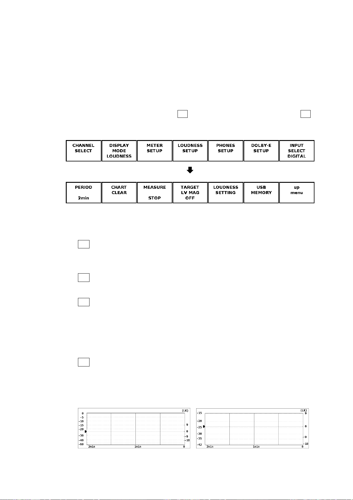
6. MEASUREMENT DISPLAYS
Tar getLV
This displays the target level. The target level varies according to the measurement
mode as shown below.
• When the measurement mode is not EBU : -24.0 (LKFS)
• When the measurement mode is EBU : -23.0 (LUFS)
6.5.2 Configuring the Loudness Display
To configure the loudness display, press F•4 LOUDNESS SETUP in the audio menu. F•4
LOUDNESS SETUP appears when the loudness display is showing.
Audio menu
Loudness setup menu
Figure 6-38 Loudness setup menu
The items in the loudness setup menu are described below.
● F•1 PERIOD
Select the measurement time from the available settings below.
2min, 10min, 30min, 1hour, 2hour
● F•2 CHART CLEAR
Press this to clear the chart, peak level, and numeric displays.
● F•3 MEASURE
Press this to start and stop measurements. When measurements are being performed,
“MEAS” is displayed in the center of the screen. When measurements are stopped,
“STOP” is displayed. When the LV 58SER40A is standing by, “WAIT” is displayed.
This menu appears when Trigger has been set to OFF or Mute on the loudness setting
screen.
● F•4 TARGET LV MAG
If you set this to ON, the target level is displayed on a scale that has a full scale
ranging from -18 to +9 (LK/LU). This is not applied to the meter at the bottom of the
display.
TARGET LV MAG = OFF TARGET LV MAG = ON
Figure 6-39 Setting the scale
79
Page 83

6. MEASUREMENT DISPLAYS
● F•5 LOUDNESS SETTING
Press this to configure the loudness and channel settings.
The items on the loudness setting screen are described below.
Figure 6-40 Loudness setting screen
• Measure Mode
Select the measurement mode. Depending on the measurement mode, the
parameters vary as shown below.
Table 6-58 Selecting the measurement mode
Measure Mode
BS1770-2 ARIB EBU ATSC
Corresponding Standard ITU-R BS.1770-2 ARIB TR-B32 EBU R128 ATSC A/85
Target Level -24.0 (LKFS) -24.0 (LKFS) -23.0 (LUFS) -24.0 (LKFS)
Block Size (ms) 400 400 400 400
Overlap Size (%) 75 75 75 0
Absolute Gating -70.0 (LKFS) -70.0 (LKFS) -70.0 (LUFS) -
Relative Gating -10.0 (LKFS) -10.0 (LKFS) -10.0 (LUFS) -
• LFE Gain
When Main is set to 5.1 or CUSTOM on the channel mapping screen, select whether
to measure LFEch. When this is set to ON, you can set the LFEch gain to a value from
0 to 10.
• ShortTerm Loudness
Set the time that is used to calculate the short-term loudness to a value from 200 to
10000 (ms).
• Momentary Loudness
Set the time that is used to calculate the momentary loudness to a value from 200 to
10000 (ms).
80
Page 84
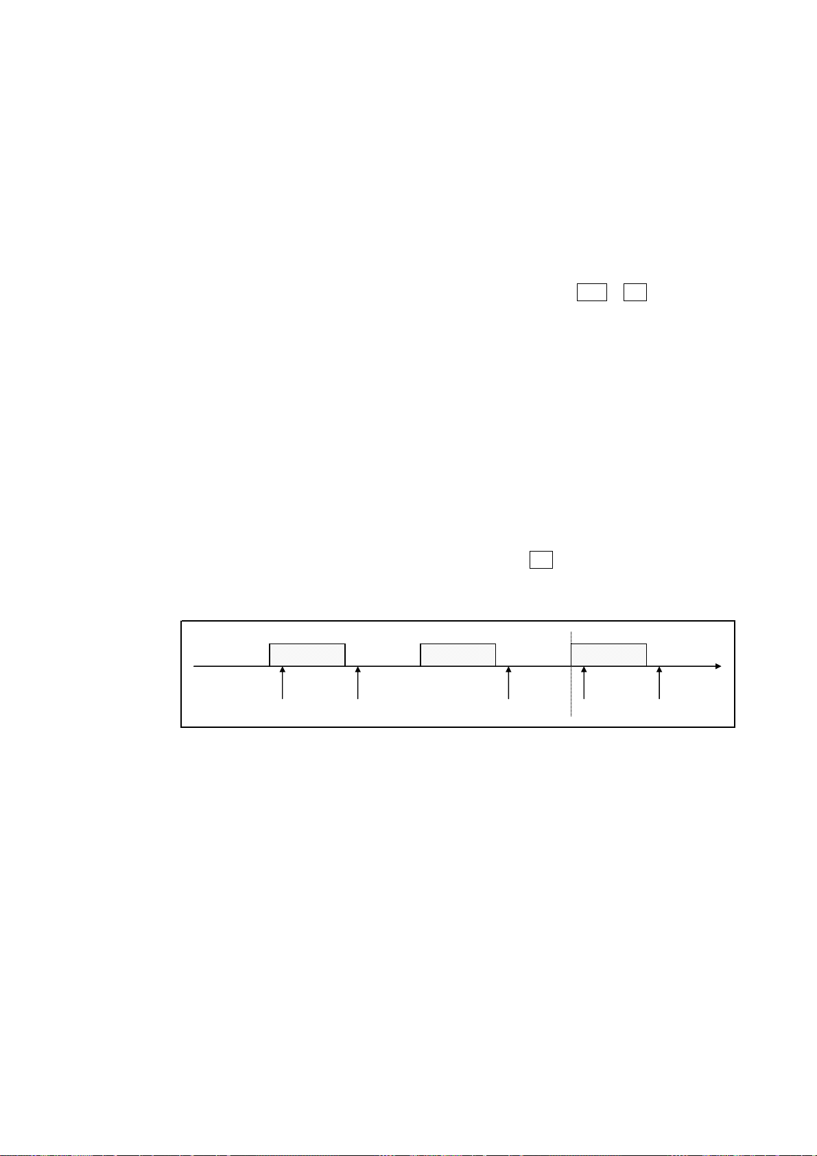
• Loudness Response
b
6. MEASUREMENT DISPLAYS
Set the response model to Short Term or Momentary.
• Loudness Auto Measure
Select the automatic loudness measurement mode from the available settings below.
OFF: Automatic measurement is disabled. You must set the loudness
measurement on the loudness setup menu.
Remote: Measurement start, stop, and clear are executed through the remote
control connector.
To use the remote terminal, you have to press SYS > F•2 PLATFORM
SETUP, and then set Remote Select to Recall and Loudness on the
REMOTE tab. When you make this setting, pin 23 (/P7) is assigned to
clearing measurements and pin 24 (/P8) is assigned to starting and
stopping measurements.
Timecode: Measurement start and stop are executed on the basis of the time
codes embedded in the SDI signals. Set the Start Time and End Time
values.
In the unit setup of the LV 58SER01(A) or LV 58SER06, you have to
set Time Code to a value other than Real Time.
Mute: Measurement start, stop, and clear and storage to USB memory are
executed through input signals as described below.
If you select Mute, on the loudness setup menu, press F•3 MEASURE to select
START, and then apply the material to measure. “WAIT” appears in the center of the
display.
No sound No sound No sound No sound
Audio (leader) Audio (body) Audio (leader)
c
a b a
Figure 6-41 Mute explanation
a) When and audio (leader) is received, loudness measurement is cleared.
b) Loudness measurement starts 1 second after the detection of no sound. “MEAS”
appears in the center of the display.
c) Loudness measurement stops 3 seconds after the detection of no sound. If a USB
memory device is connected, the loudness data is automatically saved to the
device. “WAIT” appears in the center of the display.
You can measure multiple materials in succession by applying subsequent materials.
81
Page 85

6. MEASUREMENT DISPLAYS
The items on the channel mapping screen are described below.
Figure 6-42 Channel mapping screen
• Main
Select the main loudness measurement channel from the available settings below.
MONO: The channel that you select for L-Rch is measured.
STEREO: The channels that you select for Lch and Rch are measured.
5.1: The channels that you select for Lch, Rch, Cch, LFEch, Lsch, and Rsch are
measured. You can also turn LFEch off.
CUSTOM: The channels that you select for Lch, Rch, Cch, LFEch, Lsch, and Rsch are
measured. You can also turn LFEch off. Channels set to Non_Connection
will not be measured.
• Sub
Select the sub loudness measurement channel from the available settings below.
MONO: The channel that you select for L-Rch is measured.
STEREO: The channels that you select for Lch and Rch are measured.
OFF: Sub loudness is not measured.
82
Page 86

6. MEASUREMENT DISPLAYS
● F•6 USB MEMORY
You can save the loudness data to a USB memory device as a .csv file or as a text file.
To do so, follow the procedure below.
1. Connect a USB memory device to the USB port.
2. Press F•6 USB MEMORY.
The file list display appears.
This menu item appears when USB memory is connected.
Figure 6-43 File list display
3. Press F•1 NAME INPUT.
The file name input display appears.
Figure 6-44 File name input display
83
Page 87

6. MEASUREMENT DISPLAYS
4. Enter a file name using up to 20 characters.
The key operations on the file name input display are explained below.
Spaces are invalid. The spaces that you enter are ignored.
F•1 CLEAR ALL : Deletes all characters.
F•2 DELETE : Deletes the character at the cursor position.
F•3 INSERT : Inserts an underscore (_) at the cursor position.
F•4 <= : Moves the cursor to the left.
F•5 => : Moves the cursor to the right.
F•6 CHAR SET : Enters the selected character.
F•D : Turn to select a character, and press to enter the character.
You can copy the file name of an already saved file. To copy a file name, move the
cursor to the file in the file list whose name you want to copy, and then press the F•D. If
F•5 FILENAME AUTO INC is set to ON, a two-digit number will automatically be
added to the end of the copied file name.
5. Press F•7 up menu.
6. Press F•2 STORE.
When the message “Saving file - Please wait.” disappears, the file has been
successfully saved.
If there is more than one file with the same name in the USB memory, an overwrite
confirmation menu appears. If you want to overwrite the current file, press F•1 OVER
WR YES. Otherwise, press F•3 OVER WR NO.
Deleting a Loudness Data
To delete a loudness data that has been saved to USB memory, select the loudness
file in the file list display, and then press F•4 FILE DELETE. To delete the file, press
F•1 DELETE YES. To cancel the delete operation, press F•3 DELETE NO.
Setting File Numbering
When you set F•5 FILENAME AUTO INC in the file list display to ON, a two-digit
number is automatically added to the entered file name (starting with 00). The default
setting is OFF.
This number returns to 00 if you initialize the settings or turn the power on and off.
USB Memory Folder Structure
Loudness data is saved in the LOUDNESS folder. If there is no LOUDNESS folder in
the USB memory, the LV 5800/7800 will create a folder automatically.
USB memory
LOUDNESS
└
├
└
****.CSV
****.TXT
84
Page 88
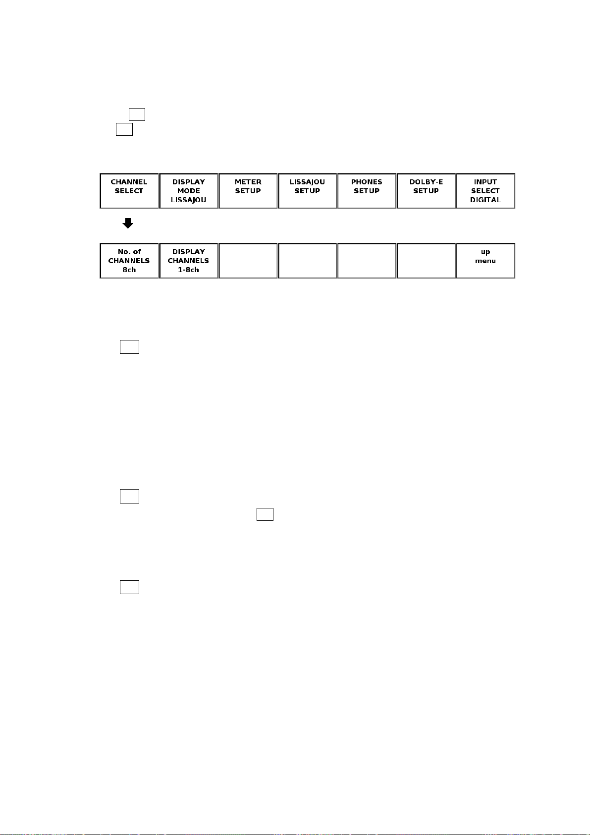
7. CONFIGURATION
7. CONFIGURATION
7.1 Selecting Measurement Channels
Press F•1 CHANNEL SELECT in the audio menu to select the measurement channels. If you
set F•7 INPUT SELECT in the audio menu to ANALOG or set DECODE MODE to DOLBY-E
or DOLBY-DIGITAL when the 2-screen display is enabled, this menu will not appear.
Audio menu
Channel selection menu
The channel selection menu is described below.
● F•1 No.of CHANNELS
● F•2 DISPLAY CHANNELS
Figure 7-1 Channel selection menu
Select the number of channels you want to measure from the available settings below.
When the 2-screen display is enabled, DECODE MODE is set to DOLBY-E or
DOLBY-DIGITAL, or the loudness display is enabled, the number of channels is fixed to
eight, and this menu does not appear.
It takes approximately 15 seconds to switch the number of channels.
8ch Measures the audio signals from channels 1 to 8 or from channels 9 to
16.
16ch Measures the audio signals from channels 1 to 16.
This menu appears if you set F•1 No.of CHANNELS to 8ch or enable the 2-screen
display. Select the channels you want to measure from the available settings below.
1-8ch Measures the audio signals from channels 1 to 8.
9-16ch Measures the audio signals from channels 9 to 16.
● F•3 MIX MODE (LV 58SER40A only)
When DECODE MODE is set to DOLBY-E or DOLBY-DIGITAL, select the channels you
want to measure from the available settings below. When using the 2-screen display, the
number of channels is fixed at OFF, and this menu does not appear.
It takes approximately 15 seconds to switch the number of measurement channels.
OFF Eight Dolby signal channels are measured.
ON Eight audio signal channels and eight Dolby signal channels are
measured at the same time.
When INPUT GROUP is a channel group from CH1/2 to CH7/8, audio
signal channels 1 to 8 are displayed. When INPUT GROUP is a channel
group from CH9/10 to CH15/16, audio signal channels 9 to 16 are
displayed.
85
Page 89
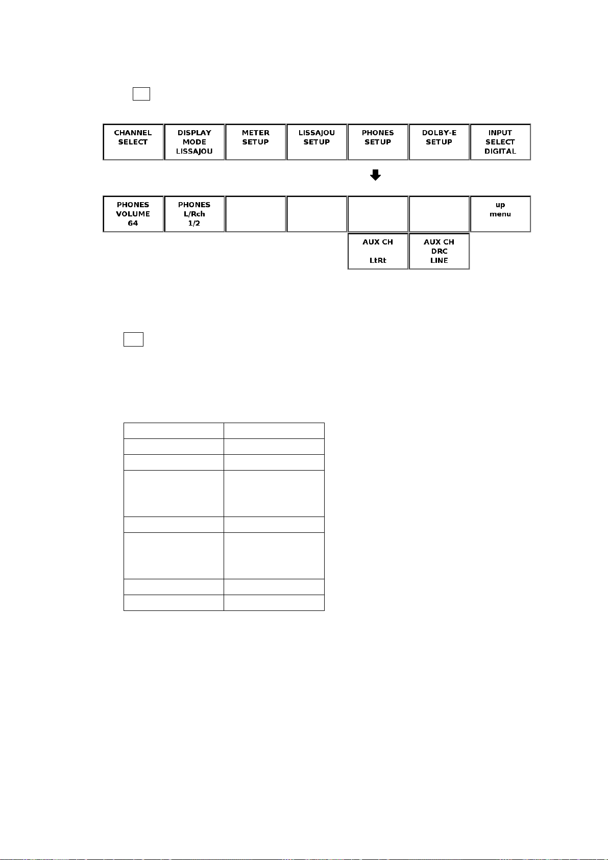
7. CONFIGURATION
7.2 Configuring the Headphone Settings
Press F•5 PHONES SETUP in the audio menu to configure the headphone settings.
Audio menu
Headphone setup menu
Figure 7-2 Headphone setup menu
The headphone setup menu is described below.
● F•1 PHONES VOLUME (LV 5800 only)
Turn F•D to set the headphone volume. The selectable range is from -128 to 127 (256
levels). Pressing F•D resets the intensity to the default value (64). You can set the
PHONES VOLUME value in 0.5-db steps. The level-to-dB conversion is given below.
Table 7-1 PHONES VOLUME dB conversion table
PHONES VOLUME dB
127 0.0
126 -0.5
•
•
•
64 -31.5
•
•
•
-127 -127.0
-128 -∞(=MUTE)
•
•
•
•
•
•
This menu does not appear when the LV58SER40(A) is installed in the LV 7800. Use the
VOLUME knob on the front panel to set the headphone volume.
86
Page 90

7. CONFIGURATION
● F•2 PHONES L/Rch
Select the channel pair that you want to output through the headphone jack. If you set
F•7 INPUT SELECT in the audio menu to ANALOG, the channel pairs will be fixed at
L/R.
1/2 Assigns channel 1 and 2 to the left and right channels, respectively.
3/4 Assigns channel 3 and 4 to the left and right channels, respectively.
5/6 Assigns channel 5 and 6 to the left and right channels, respectively.
7/8 Assigns channel 7 and 8 to the left and right channels, respectively.
9/10 Assigns channel 9 and 10 to the left and right channels, respectively.
11/12 Assigns channel 11 and 12 to the left and right channels, respectively.
13/14 Assigns channel 13 and 14 to the left and right channels, respectively.
15/16 Assigns channel 15 and 16 to the left and right channels, respectively.
Lt/Rt Assigns Lt and Rt to the left and right channels, respectively.
For information about Lt and Rt, see section 6.1.2, “Configuring the
Lissajous Display
.” (Available only on the LV 58SER40A)
D1/D2 Assigns Dolby channel 1 and 2 to the left and right channels,
respectively.
D3/D4 Assigns Dolby channel 3 and 4 to the left and right channels,
respectively.
D5/D6 Assigns Dolby channel 5 and 6 to the left and right channels,
respectively.
D7/D8 Assigns Dolby channel 7 and 8 to the left and right channels,
respectively.
DAUX1/DAUX2
Assigns AUX1 and AUX2 to the left and right channels, respectively. You
can select these settings when you set DECODE MODE to DOLBY-E or
DOLBY-DIGITAL using F•1 CHANNEL SETTING in the Dolby setup
menu. (Available only on the LV 58SER40A)
● F•5 AUX CH (LV 58SER40A only)
This menu appears if you set F•2 PHONES L/Rch to DAUX1/DAUX2. Select the AUX
CH function from below.
LtRt, LoRo, MONO, MUTE
● F•6 AUX CH DRC (LV 58SER40A only)
This menu appears if you set F•2 PHONES L/Rch to DAUX1/DAUX2. Select the AUX
CH dynamic range control (DRC) from below.
LINE, RF
87
Page 91

7.3 Dolby Setup
Press F•6 DOLBY-E SETUP in the audio menu to configure the Dolby settings. This menu
appears when the Dolby E option is installed. However, if you set F•7 INPUT SELECT in the
audio menu to ANALOG, this menu will not appear.
Audio menu
7. CONFIGURATION
Dolby setup menu
Figure 7-3 Dolby setup menu
The Dolby setup menu is described below.
● F•1 CHANNEL SETTING
Set the Dolby signal decode mode and the input channel group. The function keys in the
channel setting screen operate as follows:
F•1 COMPLETE Applies the settings and closes the channel setting screen.
F•7 CANCEL Closes the channel setting screen without applying the settings.
Figure 7-4 Channel setting screen
88
Page 92

7. CONFIGURATION
The items in the channel setting screen are described below.
DECODE MODE
OFF Select this to not measure Dolby signals.
DOLBY-E Select this to measure Dolby E signals.
DOLBY-DIGITAL Select this to measure Dolby Digital signals.
INPUT GROUP
Select the channel group that Dolby signals will be applied to. If DECODE MODE is set
to OFF, you will not be able to set the channel group.
● F•2 DOLBY E DIALNORM
This menu appears when you set DECODE MODE to DOLBY-E using F•1 CHANNEL
SETTING. Set the Dolby E signal dialog normalization to on or off.
● F•3 DOLBY E PULLDOWN
This menu appears when you set DECODE MODE to DOLBY-E using F•1 CHANNEL
SETTING. Set the Dolby E signal pulldown to on or off.
● F•2 DOLBY D LISTENING
This menu appears when you set DECODE MODE to DOLBY-DIGITAL using F•1
CHANNEL SETTING. Select the Dolby Digital signal listening mode from below.
FULL, EX, 3stereo, PHANTOM, STEREO, MONO
● F•3 DOLBY D PROLOGIC
This menu appears when you set DECODE MODE to DOLBY-DIGITAL using F•1
CHANNEL SETTING. Set the Dolby Digital Pro Logic to on or off.
● F•4 DOLBY D DRC
This menu appears when you set DECODE MODE to DOLBY-DIGITAL using F•1
CHANNEL SETTING. Select the Dolby Digital dynamic range control (DRC) from below.
BYPASS, LINE, RF
89
Page 93

7. CONFIGURATION
7.4 Configuring the Input Signal Settings
Press F•7 INPUT SELECT in the audio menu to set the measurement signal to DIGITAL or
ANALOG (LV 58SER40A only). This menu appears when you select the unit number in which
the LV 58SER40A is installed.
DIGITAL Measures the digital audio signals that are received through this unit’s BNC
connectors.
ANALOG Measures the analog audio signals that are received through the rear panel
remote connector. When you select ANALOG, the measurement channels
are automatically set to L and R channels, and the single Lissajous display
appears. (When using the 2-screen display, select LISSAJOU or METER.)
You cannot configure Dolby settings.
Audio menu
Figure 7-5 Input signal selection
To measure analog audio signals, set INPUT SELECT to ANALOG, and then apply the
signals to the remote connector pins 10 to 13. The remote connector diagram and pin
arrangement are given below. For a description of other pins, see the LV 5800 Instruction
Manual.
Figure 7-6 Remote connector diagram
Table 7-2 Remote connector pin arrangement
Pin # Name I/O Pin # Name I/O Pin # Name I/O
1 ALARM1 OUT 10 LCH+ IN 18 /P2 IN
2 GND GND 11 LCH- IN 19 /P3 IN
3 /CH_A IN 12 RCH+ IN 20 /P4 IN
4 /CH_B IN 13 RCH- IN 21 /P5 IN
5 NC - 14 GND GND 22 /P6 IN
6 NC - 15 ALARM2 OUT 23 /P7 IN
7 NC - 16 ALARM3 OUT 24 /P8 IN
8 NC - 17 /P1 IN 25 ALARM4 OUT
9 NC -
90
Page 94

7.5 System Configuration
Press SYS > F•1 UNIT SETUP > F•# UNIT# SETUP* to display the unit setup screen. You
can use this setup screen to configure rear panel BNC I/O settings and error detection
settings.
The function keys in the unit setup screen operate as follows:
F•1 COMPLETE Applies the settings and closes the unit setup screen.
F•7 CANCEL Closes the unit setup screen without applying the settings.
* Select the unit number in which the LV 58SER40(A) is installed.
7. CONFIGURATION
Figure 7-7 Unit setup screen
The items in the unit setup screen are described below.
● External BNC Select
• External BNC
Configure this unit’s BNC connector I/O settings. The BNC connector settings apply to
all BNC connectors including those on the optional I/O expansion unit.
These settings are not initialized even if you initialize the system settings by pressing
SYS > F•7 INITIALIZE. They are also not stored even if you store settings to a preset
memory location by pressing MEM > F•2 STORE. The factory default setting is
INPUT.
INPUT All BNC connectors on this unit are set to input.
OUTPUT All BNC connectors on this unit are set to output.
91
Page 95

● Error Setup
7. CONFIGURATION
Set whether or not to display errors in the status screen.
ON Displays errors in the status screen.
OFF Does not display errors in the status screen.
• Level Over
Turn the input signal level over error on or off.
• Clip
Turn the input signal clip error on or off.
If you select ON, you can select the duration. Use F•D to set the conditions for
counting clip errors. The error is incremented in the status screen if the number of
times clipped signals are detected consecutively exceeds this setting.
• Mute
Turn the input signal mute error on or off.
If you select ON, you can select the duration. Use F•D to set the conditions for
counting mute errors. The error is incremented in the status screen if the number of
times mute signals are detected consecutively exceeds this setting.
• Parity Error
Turn the input signal parity error on or off.
• Validity Error
Turn the input signal validity error on or off.
• CRC Error
Turn the input signal CRC error on or off.
• Code Violation
Turn the input signal code violation error on or off.
92
Page 96

8. FIRMWARE REVISION HISTORY
8. FIRMWARE REVISION HISTORY
This manual was written for the following firmware versions:
• Ver. 9.6 on the LV 5800
• Ver. 4.3 on the LV 7800
To confirm the version, press a key in order of SYS → F•5 SYSTEM INFORMATION.
● Ver 9.6 on the LV 5800 / Ver 4.2 on the LV 7800
• An automatic mute detection measurement feature has been added to loudness display
of the LV 58SER40A.
● Ver 9.3 on the LV 5800 / Ver 3.9 on the LV 7800
• The single Lissajous level meter on the LV 58SER40A now displays eight channels (two
channels previously).
• A function for zooming in on the range of 3 dB below the reference to 3 dB above the
reference level was added to the LV 58SER40A sound level meter display.
• A function for simultaneously displaying two sound sources was added to the LV
58SER40A loudness display.
• Peak value display was added to the LV 58SER40A loudness display.
• Audio mode display was added to the LV 58SER40A loudness display.
• Inter-channel correlation meter display was added to the LV 58SER40A loudness
display.
● Ver 7.9 on the LV 5800 / Ver 2.6 on the LV 7800
• A loudness display feature that complies with the ITU, ARIB, and EBU standards has
● Ver 6.8 on the LV 5800 / Ver 1.4 on the LV 7800
● Ver 6.5 on the LV 5800 / Ver 1.4 on the LV 7800
● Ver 5.4 on the LV 5800
● Ver 5.1 on the LV 5800
● Ver. 3.5 on the LV 5800
● Ver. 3.3 on the LV 5800
been added to the LV 58SER40A.
• The sound image display feature has been changed to a surround display feature on the
LV 58SER40(A).
• A long-term loudness graph display feature has been added to the LV 58SER40A.
• An event log feature has been added to the LV 58SER40(A).
• On the LV 58SER40A, MIX MODE was added to CHANNEL SELECT.
• Loudness was added to the response characteristics in the LV 58SER40A audio level
meter.
• The LV 58SER40A can be used.
• On the LV 58SER40, the audio level meter drawing speed was increased.
93
Page 97

Index
—A—
ALIGN.................................................................. 61, 66
AUTO GAIN......................................................... 33, 38
AUX CH ..................................................................... 87
AUX CH DRC ............................................................ 87
—C—
CHANNEL MAPPING.......................................... 34, 38
CHANNEL SELECT................................................... 85
CHANNEL SETTING................................................. 88
CHANNEL STATUS................................................... 61
CHART CLEAR ......................................................... 79
CLEAR....................................................................... 69
—D—
DISPLAY.................................................................... 33
DISPLAY CHANNEL............................................ 61, 66
DISPLAY CHANNELS ............................................... 85
DISPLAY MODE ................................ 30, 36, 39, 72, 77
DISPLAY PROGRAM .......................................... 43, 53
DOLBY D DRC .......................................................... 89
DOLBY D LISTENING ............................................... 89
DOLBY D METADATA ............................................... 51
DOLBY D PROLOGIC............................................... 89
DOLBY E DIALNORM ............................................... 89
DOLBY E METADATA ............................................... 43
DOLBY E PULLDOWN.............................................. 89
DOLBY-E SETUP ...................................................... 88
DYNAMIC RANGE .................................................... 74
—E—
EBI METADATA ................................................... 53, 57
EVENT LOG .............................................................. 67
—I—
INPUT SELECT..........................................................90
—L—
LISSAJOU ..................................................................30
LISSAJOU INTEN ......................................................33
LISSAJOU SETUP .....................................................32
LOG............................................................................69
LOG MODE ................................................................69
LOUDNESS................................................................77
LOUDNESS SETTING ...............................................80
LOUDNESS SETUP...................................................79
—M—
MEASURE..................................................................79
METER.......................................................................72
METER SETTING ......................................................76
METER SETUP..........................................................74
MIX MODE .................................................................85
—N—
NAME INPUT .......................................................70, 83
No.of CHANNELS ......................................................85
—P—
PEAK HOLD...............................................................75
PERIOD......................................................................79
PHONES L/Rch..........................................................87
PHONES SETUP .......................................................86
PHONES VOLUME ....................................................86
—R—
—F—
FILE DELETE ...................................................... 71, 84
FILENAME AUTO INC......................................... 71, 84
FORM ........................................................................ 33
RESPONSE ...............................................................75
—S—
SCALE INTEN......................................................33, 37
Page 98

STATUS..................................................................... 39
STATUS SETUP........................................................ 43
STORE ................................................................ 71, 84
SURROUND.............................................................. 36
SURROUND 5.1........................................................ 37
SURROUND INTEN .................................................. 37
SURROUND SETUP ................................................. 37
—T—
TARGET LV MAG.......................................................79
—U—
UNIT SETUP ..............................................................91
USB MEMORY.....................................................70, 83
USER BIT...................................................................66
Page 99

Following information is for Chinese RoHS only
所含有毒有害物质信息
部件号码:
此标志适用于在中国销售的电子信息产品,依据2006年2月28日公布的
《电子信息产品污染控制管理办法》以及SJ/T11364-2006《电子信息产品污染
控制标识要求》,表示该产品在使用完结后可再利用。数字表示的是环境保护使
用期限,只要遵守与本产品有关的安全和使用上的注意事项,从制造日算起在数
字所表示的年限内,产品不会产生环境污染和对人体、财产的影响。
产品适当使用后报废的方法请遵从电子信息产品的回收、再利用相关法令。
详细请咨询各级政府主管部门。
部件名称
Parts 铅 汞 镉 六价铬 多溴联苯 多溴二苯醚
实装基板 × ○ ○ ○ ○ ○
主体部 × ○ ○ ○ ○ ○
附件 × ○ ○ ○ ○ ○
包装材 ○ ○ ○ ○ ○ ○
有毒有害物质或元素 Hazardous Substances in each Part
(Pb) (Hg) (Cd) (Cr(Ⅵ)) (PBB) (PBDE)
LV 58SER40A
产品中有毒有害物质或元素的名称及含量
备注)
○:表示该有毒有害物质在该部件所有均质材料中的含量均在SJ/T11363-2006 规定的限量要求以下。
×:表示该有毒有害物质或元素至少在该部件的某一均质材料中的含量超出SJ/T11363-2006
标准规定的限量要求。
Ver.3
Page 100

LEADER ELECTRONICS CORP.
2-6-33 Tsunashima-Higashi, Kohoku-ku, Yokohama 223-8505, Japan
PHONE:81-45-541-2123 FAX:81-45-541-2823 http://www.leader.co.jp
Aug. 21, 2012 Ver.7 (FW Ver.9.6)
 Loading...