

Page 1

LV 57SER70 Instruction Manual
TABLE OF CONTENTS
1. DESCRIPTION ........................................................................................................................ 2
2. FEATURES .............................................................................................................................. 2
3. SPECIFICATIONS.................................................................................................................... 3
3.1 Supported Formats ......................................................................................................... 3
3.2 Eye Pattern Display Section ............................................................................................ 3
3.3 Jitter Display Section .......................................................................................................3
3.4 Jitter Output ..................................................................................................................... 4
3.5 EXT REF Input for Eye Patterns ..................................................................................... 4
4. EYE PATTERN MENU STRUCTURE ...................................................................................... 5
5. POSITION and INTENSITY ADJUSTMENT ............................................................................ 6
5.1 Position Adjustment......................................................................................................... 6
5.2 Brightness Adjustment .................................................................................................... 6
6. USING THE EYE PATTERN DISPLAY MODE ......................................................................... 7
6.1 Sweep Settings ...............................................................................................................8
6.2 Filter Selection ................................................................................................................ 8
6.3 Automatic Measurement ................................................................................................. 9
6.4 Cursor Measurement ...................................................................................................... 9
6.4.1 Cursor Display .................................................................................................. 10
6.4.2 X-Axis/Y-Axis Cursor Selection ......................................................................... 10
6.4.3 Cursor Measurement Unit Selection ................................................................. 10
6.4.4 Cursor Movement ............................................................................................. 10
6.4.5 Cursor Measurement ........................................................................................ 11
7. USING THE JITTER DISPLAY MODE ................................................................................... 13
7.1 Gain Setting .................................................................................................................. 13
7.2 Jitter Output (JITTER OUT) .......................................................................................... 13
8. USING THE HISTOGRAM DISPLAY MODE ......................................................................... 14
8.1 Histogram Sweep (HIST SWEEP) Setting .................................................................... 14
9. External Trigger (EXT TRIG) .................................................................................................. 15
-1-
Page 2

LV 57SER70 Instruction Manual
1. DESCRIPTION
This option model adds eye pattern display functions of HD and SD-SDI signals to the standard
LV 5700/LV 5710 model. (Only HD-SDI signals are supported on the LV 5710.)
Measurements of various parameters such as the amplitude, rise time, fall time, timing jitter, and
alignment jitter of SDI signals are possible from the displayed eye patterns.
For a description of the specifications other than those of the newly added eye pattern function,
see the specifications of the standard model.
2. FEATURES
• Enables observation of HD-SDI (SMPTE292M) and SD-SDI (SMPTE259M) eye patterns.
•Displays numerically the amplitude, the amount of jitter, the rise time, and the fall time through
the auto measurement function of eye patterns.
• Built-in clock regeneration circuit conforming to SMPTE EG33 allows timing jitter and alignment
jitter measurements.
•Provides an external SDI TRIG input for accurately measuring eye pattern jitters.
•Provides jitter display mode for measuring only the jitter component of the SDI signal.
This enables measurements of jitter components that are difficult to be read from eye patterns.
• The histogram display function of jitter components enables the observation of the distribution
of the jitter within a unit time.
The current jitter waveform is also displayed simultaneously.
-2-
Page 3

3. SPECIFICATIONS
3.1 Supported Formats
Standards HD SMPTE292M
Data Rate HD 1.485 Gbps or 1.485/1.001 Gbps
3.2 Eye Pattern Display Section
Display Displays the SDI input waveform before equalizing
Method Equivalent time sampling method
Frequency Range 10 MHz to 2.5 GHz Within +1, -3 dB
Amplitude Accuracy Within 800 mV ± 5 % for 800 mV input
Time Axis 2 waveform display 100 ps/div
Time Axis Accuracy Within ±3 %
Jitter Filter 10Hz HPF (for HD and SD timing jitter measurement)
Cursor Measurement Amplitude measurement using the Y cursor
Automatic Measurement Measures and displays the amplitude, the jitter, the rise
LV 57SER70 Instruction Manual
SD SMPTE259M (LV 5700 only)
SD 270 Mbps (LV 5700 only)
4 waveform display 200 ps/div
16 waveform display 800 ps/div
100 Hz HPF
1 kHz HPF (for SD alignment jitter measurement)
10 kHz HPF
100 kHz HPF (for HD alignment jitter measurement)
Time and jitter measurements using the X cursor
Rise time and fall time measurements using the Tr and Tf
cursors
time, and the fall time from the eye pattern
Can be turned on/off
3.3 Jitter Display Section
Display Displays the jitter component of the SDI input
Method Phase detection method
Amplitude Accuracy Within ±10 % when applying 10 KHz 1 UI jitter (using 100
Jitter Filter 10 Hz HPF (for HD and SD timing jitter measurement)
Cursor Measurement Jitter measurement using cursors
Automatic Measurement Displays the amount of jitter in time (sec) and unit interval
Hz filter)
100 Hz HPF
1 kHz HPF (for SD alignment jitter measurement)
10 kHz HPF
100 kHz HPF (for HD alignment jitter measurement)
(UIp-p)
-3-
Page 4

LV 57SER70 Instruction Manual
3.4 Jitter Output
Output Connector 75 Ω BNC connector, 1 output
Output Level Within 200 mV/UI ±20 % (at 10 kHz jitter frequency and
75 Ω termination)
* Jitter output is enabled in jitter display mode.
3.5 EXT REF Input for Eye Patterns
Standard HD SMPTE292M
SD SMPTE259M (LV 5700 only)
Data Rate HD 1.485 Gbps or 1.485/1.001 Gbps
SD 270 Mbps (LV 5700 only)
Input Connector 75 Ω BNC connector, 1 input
Input Level Signal source amplitude Within 0.8 Vp-p ±10 %
Input Format HD SMPTE292M
SD SMPTE259M (LV 5700 only)
Maximum Input Voltage ±2 V (DC + Peak AC)
-4-
Page 5

LV 57SER70 Instruction Manual
4. EYE PATTERN MENU STRUCTURE
The hierarchical structure of the eye pattern menu is shown below.
Underlined sections indicate initial settings.
-5-
Page 6

LV 57SER70 Instruction Manual
5. POSITION and INTENSITY ADJUSTMENT
5.1 Position Adjustment
You can adjust the vertical position of the eye pattern and jitter
waveform on the screen using the V POS control i and the
horizontal position using the H POS control !0.
The V POS control i and H POS control !0 also function as
switches. Press the switch to reset the display position of the
eye pattern to the reference position.
5.2 Brightness Adjustment
To adjust the intensity (brightness) of the eye pattern or the
scale, select F·1 INTEN from the eye display menu that
appears when you press the EYE key !6.
Press F·1 EYE INTEN from the brightness adjustment menu
and turn the function dial (F·D) !8 to adjust the brightness of
the waveform.
Likewise, press F·2 SCALE INTEN and turn the function dial
(F·D) !8 to adjust the brightness of the scale.
The function dial (F·D) !8 also functions as a switch. Press the
switch to reset the brightness of eye patterns to the reference
value (0).
Figure 5.1 Panel around the
EYE key !6
-6-
Page 7
LV 57SER70 Instruction Manual
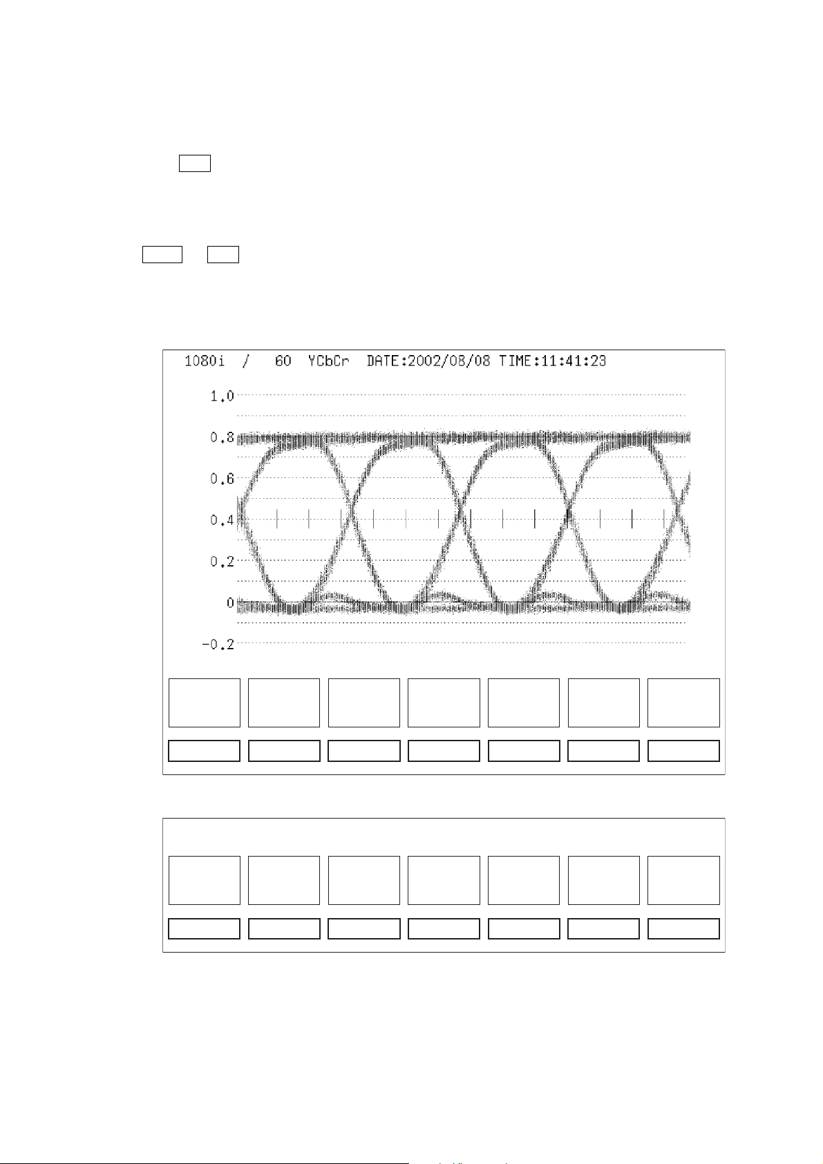
6. USING THE EYE PATTERN DISPLAY MODE
To display eye patterns, press the EYE key !6.
Then, press F·3 MODE to select EYE from the eye display menu. As shown in Figure 6.1 and
6.2, the screen displays the eye pattern, the scale, and the eye display menu. You can enter
various settings from the eye display menu.
The mode setting switches the display as follows.
[ EYE → F·3 MODE : EYE / JITTER / HIST ]
EYE: Displays eye patterns
JITTER: Displays jitter waveforms
HIST: Displays histogram waveforms
INTEN
F·1
SWEEP
4UI
F·2 F·3 F·4 F·5 F·6 F·7
MODE
EYE
CURSOR AUTO
MEASURE
OFF
FILTER
100kHz
next
menu
Figure 6.1 Eye display menu page 1
F·1
HIST
SWEEP
SLOW
F·2 F·3 F·4 F·5 F·6 F·7
JITTER
GAIN
×8
REF
INT
FILTER
100kHz
prev
menu
Figure 6.2 Eye display menu page 2
*When the 10 Hz filter is selected, it takes few seconds to lock.
* ARIB (ARIB TR-B7) recommends that color bar signals be used for the jitter
measurement of eye patterns.
-7-
Page 8
6.1 Sweep Settings
To set a sweep on the eye pattern, select F·2 SWEEP from the eye display menu that
appears when you press the EYE key !6.
[ EYE → F·2 SWEEP : 2UI / 4UI / 16UI ]
2UI: Displays 2 eye patterns
4UI: Displays 4 eye patterns
16UI: Displays 16 eye patterns
6.2 Filter Selection
Set the bandwidth used when measuring the jitter of SDI signals.
[ EYE → F·6 FILTER : 10Hz / 100Hz / 1kHz / 10kHz / 100kHz ]
If the filter is set to 10 Hz, the eye pattern jitter over the entire bandwidth greater than or
equal to 10 Hz is displayed. Likewise, if set to 100 kHz, only the jitter over the bandwidth
greater than or equal to 100 kHz is displayed.
This setting enables you to determine the frequency components of the jitter of the SDI
input signal.
LV 57SER70 Instruction Manual
In addition, SMPTE stipulates that the timing jitter and alignment jitter be measured.
The filter settings in this case are 10 Hz for HD and SD for timing jitter and 100 kHz for HD
and 1 kHz for SD for alignment jitter.
In addition, ARIB (ARIB TR-B7) recommends that color bar signals be used for the jitter
measurement of eye patterns.
The filter response is shown in Table 6.1.
Frequency Range Filter Response
10 Hz Displays the jitter for frequencies greater than or equal to 10 Hz
(HD and SD timing jitters)
100 Hz Displays the jitter for frequencies greater than or equal to 100 Hz
1 kHz Displays the jitter for frequencies greater than or equal to 1 kHz
(SD alignment jitter)
10 kHz Displays the jitter for frequencies greater than or equal to 10 kHz
100 kHz Displays the jitter for frequencies greater than or equal to 100
kHz (HD alignment jitter)
Table 6.1 Filter Response
-8-
Page 9

LV 57SER70 Instruction Manual
6.3 Automatic Measurement
Automatically measures the amplitude, the rise time, the fall time, and the amount of jitter of the
eye pattern.
[ EYE → F·5 AUTO MEASURE : ON / OFF ]
When automatic measurement is turned ON, the amplitude, the rise time, the fall time, and the
amount of jitter are displayed numerically for the current eye pattern on the screen.
The automatic measurement values using this eye pattern display mode are determined through
image processing from the waveform data on the screen.
This achieves correlation with the values obtained by measuring the eye pattern using a cursor.
However, the jitter cannot be measured accurately if the eye pattern of the signal does not have
an opening or if a DC component is displayed in the opening such as in a check field signal. In
such cases, use the jitter display mode (described later).
6.4 Cursor Measurement
Cursor measurement is used to measure voltage, time, and other parameters. The REF and
DELTA cursors are used to measure the voltage and time between two points on a waveform.
To perform cursor measurements, select F·4 CURSOR from the waveform display menu that
appears when you press the EYE key !6.
The cursor measurement menu appears as shown in Figure 6.3. Select the appropriate items.
CURSOR
ON
F·1
XY SEL
Y
F·2 F·3 F·4 F·5 F·6 F·7
Y UNIT
V
FD VAR
REF
REF
SET
FILTER
100kHz
up
menu
Figure 6.3 Cursor measurement menu
Key Display Function
F·1 CURSOR Selects cursor on/off.
F·2 XY SEL Switches between the X-axis and Y-axis of the cursor.
F·3 Y UNIT/X UNIT Selects the Y-axis or X-axis cursor unit.
F·4 FD VAR Switches between REF, DELTA, TRACK of the F·D.
F·5 REF SET Sets the amplitude reference.
F·6 FILTER Sets the filter for jitter measurement.
F·7 up menu
F·D Moves the cursor
Table 6.2 Cursor measurement menu description
-9-
Page 10

LV 57SER70 Instruction Manual
6.4.1 Cursor Display
[ EYE → F·4 CURSOR → F·1 CURSOR:ON / OFF ]
To display the cursor, press F·1 CURSOR from the cursor measurement menu and select ON.
Select OFF to clear the cursor.
6.4.2 X-Axis/Y-Axis Cursor Selection
[ EYE → F·4 CURSOR → F·2 XY SEL:Y / X / Tr,Tf ]
Select the axis to perform the cursor measurement from X-axis (time) and Y-axis (amplitude).
For a description of the Tr, Tf measurement, see section 6.4.5 (5).
6.4.3 Cursor Measurement Unit Selection
(1) Selecting the Y-axis or X-axis cursor unit
[ EYE → F·4 CURSOR → F·3 Y UNIT: V / % ]
[ EYE → F·4 CURSOR → F·3 X UNIT:sec / Hz / UIp-p ]
To select the cursor unit, press F·3 Y UNIT or X UNIT, the axis selected in section
6.4.2, “X-Axis/Y-Axis Cursor Selection.”
Y-axis cursor unit
V: Volt display.
%: Displays the ratio where the difference between two arbitrary points set
by REF SET is taken to be 100 %.
X-axis cursor unit
sec: Second display.
Hz: Displays the frequency where the interval between the cursors is taken
to be one period.
UIp-p: Displays using a unit where one eye pattern is taken to be 1 UIp-p.
6.4.4 Cursor Movement
[ EYE → F·4 CURSOR → F·4 FD VAR:REF / DELTA / TRACK ]
To move the desired cursor, select F·4 FD VAR from the cursor measurement menu.
REF: Moves the reference cursor using the function dial (F·D) !8.
DELTA: Moves the DELTA cursor using the function dial (F·D) !8.
TRACK: Moves the reference and DELTA cursors simultaneously using the function dial
(F·D) !8.
-10-
Page 11

6.4.5 Cursor Measurement
(1) Measuring the amplitude
[ EYE → F·4 CURSOR → F·2 XY SEL → X → F·3 Y UNIT → V / % ]
Measures the amplitude between two arbitrary points of the waveform. Press F·3 Y
UNIT to select V or % for the unit.
V: Displays the amplitude in unit of volts.
%: Percentage where the difference between the two arbitrary points is
taken to be 100 %.
To set the reference (100 %), set the cursors on the waveform and press
the REF SET key to set the cursor range to 100%.
(2) Measuring the time
[ EYE → F·4 CURSOR → F·2 XY SEL→ X → F·3 X UNIT → sec ]
Measures the time between two arbitrary points.
Set the REF and DELTA cursors to the point of measurement on the waveform. The
measured value between the cursors is displayed at the lower-right corner of the
screen. If the DELTA cursor is positioned to the left of the REF cursor, a negative
value is displayed.
LV 57SER70 Instruction Manual
(3) Measuring the frequency
[ EYE → F·4 CURSOR → F·2 XY SEL→ X → F·3 X UNIT → Hz ]
Measures the time between two cursors and displays the frequency.
(4) Measuring the Jitter
[ EYE → F·4 CURSOR → F·2 XY SEL→ X → F·3 X UNIT → sec / UIp-p ]
Position the REF and DELTA cursors to the crossing point jitter on the waveform.
The measured value is displayed at the lower-right corner of the screen.
In jitter measurement, you can switch the unit between sec (time) and UIp-p (unit
interval).
Unit interval refers to the width of 1 clock cycle. The value is displayed where 1 clock
cycle is taken to be 100%. The unit is UIp-p.
When the bit rate of the HD-SDI signal is 1.485/1001 Gbps, 1 UI is as follows:
1 UI = 1/1.4836 GHz = 674.0 ps
And, the measured jitter value (UIp-p) is as follows:
Jitter value (UIp-p) = measured value (ps)/width of 1 clock cycle (ps)
= measured value (ps)/674 (ps)
-11-
Page 12

LV 57SER70 Instruction Manual
When the bit rate of the HD-SDI signal is 1.485 Gbps, 1 UI is as follows:
1 UI = 1/1.485 GHz = 673.4 ps
And, the measured jitter value (UIp-p) is as follows:
Jitter value (UIp-p) = measured value (ps)/width of 1 clock cycle (ps)
= measured value (ps)/673.4 (ps)
In the case of the SD-SDI signal, the bit rate is 270 Mbps. Thus, 1 UI is as follows:
1 UI = 1/270 MHz = 3.70 ns
And, the measured jitter value (UIp-p) is as follows:
Jitter value (UIp-p) = measured value (ns)/width of 1 clock cycle (ns)
= measured value (ns)/3.7 (ns)
(5) Measuring the rise time and fall time (Tr and Tf)
[ EYE → F·4 CURSOR → F·2 XY SEL→ Tr,Tf ]
This mode measures the rise time Tr or fall time Tf of the eye pattern.
First, using Y cursors, move the REF and DELTA cursors to the eye pattern
amplitude and press F·5 REF SET. The Y cursors move to the 20 % and 80 %
positions of the amplitude.
Then, by moving the cursor to the crossing points of the 20% and 80% cursors and
the waveform ,Tr and Tf can be measured.
The measured value between the cursors is displayed at the lower-right corner of
the screen.
-12-
Page 13

LV 57SER70 Instruction Manual
7. USING THE JITTER DISPLAY MODE
The jitter display mode is used to display on the time axis the phase detection output between the
reclock signal from the SDI signal and the internal reference clock. In this mode, jitters can be
accurately measured even when the eye pattern is distorted after the signal is transmitted over
the cable or when more than 1 UIp-p of jitter is present.
The displayed value indicates the jitter peak value.
To display the jitter, press F·3 MODE to select JITTER from the eye display menu.
[ EYE → F·3 EYE / JITTER / HIST ]
The screen shows the jitter waveforms, the measured values and scale, and the eye display
menu.
You can enter various settings from the eye display menu.
The usage of the filter and cursor is the same as in the eye pattern mode.
7.1 Gain Setting
To set the gain of the jitter waveform, select F·4 JITTER GAIN from the eye display menu page 2.
[ EYE → F·7 next menu → F·4 JITTER GAIN : x1 / x2 / x8 ]
x1: 1x gain
x2: 2x gain
x8: 8x gain
7.2 Jitter Output (JITTER OUT)
When in jitter display mode, the jitter signal corresponding to the displayed waveform is output to
the JITTER OUT connector on the rear panel. This output can be used to observe the jitter
components and the correlation with respect to the video signal on an external oscilloscope.
The output can also be connected to a spectrum analyzer to perform simplified frequency
analysis of the jitter signal.
The output sensitivity is within 200 mV/UI ±20 % (at 10 kHz jitter frequency and 75 Ω
termination).
-13-
Page 14

LV 57SER70 Instruction Manual
8. USING THE HISTOGRAM DISPLAY MODE
The histogram display mode is used to display the jitter distribution within unit time and can be
used to analyze the jitter. Normally, the amount of jitter is displayed using peak values. However,
by observing the histogram display, you can determine which jitter component occurs more
frequently. For example, even when the same peak jitter is displayed, the histogram distribution
may affect the error tolerance.
The histogram display indicates the frequency (count) on the vertical axis and the amount of jitter
on the horizontal axis.
Up to ±1.2 UIp-p of jitter can be displayed.
To display the histogram, press F·3 MODE to select HIST from the eye display menu.
[ EYE → F·3 : EYE / JITTER / HIST ]
The screen shows the histogram, the time axis of the jitter waveform, the scale, and the eye
display menu.
You can enter various settings from the eye display menu.
8.1 Histogram Sweep (HIST SWEEP) Setting
Selects the sweep speed of the time axis display of the jitter waveform shown in the histogram
mode. To set the histogram sweep, select F·3 HIST SWEEP from the eye display menu page 2.
[ EYE → F·7 next menu → F·3 HIST SWEEP : SLOW / FAST ]
SLOW: Slow sweep (enables observation of jitter waveforms around 10 Hz to 100 Hz)
FAST: Fast sweep (enables observation of jitter waveforms around 1 kHz to 10 kHz)
-14-
Page 15

LV 57SER70 Instruction Manual
9. External Trigger (EXT TRIG)
[ EYE → F·7 next menu → F·5 REF : INT / EXT ]
INT: Generates the synchronization signal from the SDI signal being measured.
EXT: Generates the synchronization signal from the EXT TRIG input.
If a reference SDI signal is present, the signal can be used as an external trigger to synchronize
the SDI signal being measured.
This function is used to perform eye pattern observation by supplying a trigger signal without
jitters when generation of the synchronization signal is difficult such as when the measured SDI
signal applied to INPUT A and B is transmitted over long distance or when the SDI signal
contains large amounts of jitter components.
This function enables accurate jitter measurements eliminating the influence from the jitter
contained in the measured signal.
As a specific example, when the measured signal contained jitter components greater than 1
MHz, observation was not possible due to the loss of synchronization. However, measurement is
possible even in this case by using the external trigger.
In addition, the use of the external trigger allows you to determine whether the reference SDI
signal and the SDI signal being measured are synchronized.
*When using this function, set the display to eye pattern display mode and set the FILTER to 10 Hz.
The function is valid only for the jitter measurement over the entire bandwidth in this condition.
The jitter measurement values are invalid when jitter or histogram display mode is selected or
when other FILTER settings are selected.
In addition, the SDI signal being measured and the EXT TRIG signal must be synchronized.
-15-
 Loading...