


Dukane 24A715
Models
24A715,
Installation Manual
24A715M
Master Time/Program Clock
Document No. 427-12-00014 (02)


NOTICE
To ensure the performance of our products and systems, we may occasionally make tech
nological changes and updates. Therefore, the model number suffixes (A, B, C, etc.)
listed in the manual or in the drawings may not always match the model you are using.
Unless specifically noted, this will not affect the product or its installation, operation, or
service.
FCC COMPLIANCE STATEMENT
This device complies with Part 15 of the FCC Rules. Operation is subject to the following
two conditions: (1) this device may not cause harmful interference, and (2) this device
must accept any interference received, including interference that may cause undesired
operation.
WARNING: Changes or modifications to this product not expressly approved by
the party responsible for compliance could void the user’s authority to operate this
equipment.
NOTE: This equipment has been tested and found to comply with the limits for a Class B
digital device, pursuant to Part 15 of the FCC Rules. These limits are designed to provide
reasonable protection against harmful interference in a residential installation. This
equipment generates, uses, and can radiate radio frequency energy and, if not installed
and used in accordance with the instructions, may cause harmful interference to radio
communications. However, there is no guarantee that interference will not occur in a
particular installation. If this equipment does cause harmful interference to radio or tele
vision reception, which can be determined by turning the equipment off and on, the user
is encouraged to try to correct the interference by one or more of the following measures:
-
-
•
Reorient or relocate the receiving antenna.
•
Increase the separation between the equipment and receiver.
•
Connect the equipment into an outlet on a circuit different from that to which the
receiver is connected.
•
Consult the dealer or an experienced radio TV technician for help.
This Class B digital apparatus complies with Canadian ICES-003.

FOR UNITS EQUIPPED WITH AN INTERNAL MODEM (24A715M)
NOTICE: This equipment complies with Part 68 of the FCC Rules. On the mounting
panel of this equipment is a label that contains, among other information, the FCC Regis
tration Number and Ringer Equivalence Number (REN) for this equipment. If requested,
provide this information to your Telephone Company.
The registration jack USOC for this equipment is (RJ-11). An FCC-compliant telephone
cord and modular plug is provided with this equipment. This equipment is designed to
connect to the telephone network or premises wiring using a compatible modular jack,
which is Part 68 compliant. See installation instructions for details.
-
The REN is useful to determine the quantity of devices that may be connected to the tele
phone line. Excessive RENs on the telephone line may result in the devices not ringing in
response to an incoming call. In most, but not all areas, the sum of REN of all devices
should not exceed five (5). To be certain of the number of devices that may be connected
to a line, as determined by the total REN, contact the local Telephone Company.
If your telephone equipment (Modem) causes harm to the telephone network, the Telephone Company will notify you in advance that temporary discontinuance of service may
be required, but if advance notice isn’t practical, you will be notified as soon as possible.
You will be advised of your right to file a complaint with the FCC if you believe it is
necessary.
Your Telephone Company may make changes in its facilities, equipment, operations,
or procedures that could affect the operation of your equipment. If they do, you will be
given advance notice so as to give you an opportunity to maintain uninterrupted service.
This equipment may not be used on public coin service provided by the Telephone
Company. Connection to party lines is subject to state tariffs. (Contact your state public
utility commission or corporation commission for information.)
-

SUPPLIER’S DECLARATION OF CONFORMITY
Place of Issue: St. Charles, IL
Date of Issue: August 17, 2001
Dukane Corporation, located at 2900 Dukane Drive, St. Charles, IL 60174 in the United
States of America, hereby certifies that Master Clock model 24A715M bearing labeling
identification number US:A95DT06B24A715M complies with the Federal Communica
tions Commission’s (“FCC”) Rules and Regulations 47 CFR Part 68, and the
Administrative Council on Terminal Attachments (“ACTA”)—adopted technical criteria:
TIA/EIA/IS-968, Telecommunications—Telephone Terminal Equipment—Technical Re
quirements for Connection of Terminal Equipment to the Telephone Network, July 2001.
Rolf Goehler
Rolf Goehler
General Manager, Communications Systems Division
NOTICE: The Industry Canada label identifies certified equipment. This certification
means that the equipment meets certain telecommunications network protective, operational and safety requirements. The Industry Canada does not guarantee the equipment
will operate to the user’s satisfaction.
-
-
Before installing this equipment, users should ensure that it is permissible to be connected to the facilities of the local Telecommunications Company. This equipment must
also be installed using an acceptable method of connection. In some cases, the company’s
inside wiring associated with a single line individual service may be extended by means
of a certified connector assembly (telephone extension cord). The customer should be
aware that compliance with the above conditions may not prevent degradation of service
in some situations.
Any equipment repairs made by the user, or equipment malfunctions, may give the Tele
communications Company cause to request the user to disconnect the equipment.
Users should ensure, for their own protection, that the electrical ground connections of
the power utility, telephone lines, and internal metallic water pipe system, if present, are
connected together. This precaution may be particularly important in rural areas.
CAUTION: Users should not attempt to make such connections themselves, but should
contact the appropriate electric inspection authority or electrician, as appropriate.
NOTE: The Ringer Equivalence Number (REN) assigned to each terminal device pro
vides an indication of the maximum number of terminals allowed to be connected to a
telephone interface. The termination of an interface may consist of any combination of
devices subject only to the requirement that the sum of the Ringer Equivalence Numbers
of all the devices does not exceed five (5).
-
-

A NOTE ABOUT THE LITHIUM BATTERY
The Lithium Battery (coin cell) contained in this product is NOT user-replaceable. When
replaced by an authorized Service Center, used batteries should be disposed of according
to the manufacturer’s instructions.

Table
Contents
SECTION 1—INSTALLATION
General Information . . . . . . . . . . . . . . . . . . . . . . . . . . . . . . . . . . . . . . . . . . . . . . . . . . . . . . . . . . . . . . . . . . . 1-1
Parts List. . . . . . . . . . . . . . . . . . . . . . . . . . . . . . . . . . . . . . . . . . . . . . . . . . . . . . . . . . . . . . . . . . . . . . . . . . . . 1-1
Mounting the Master Clock . . . . . . . . . . . . . . . . . . . . . . . . . . . . . . . . . . . . . . . . . . . . . . . . . . . . . . . . . . . . . 1-2
Surface Mounting . . . . . . . . . . . . . . . . . . . . . . . . . . . . . . . . . . . . . . . . . . . . . . . . . . . . . . . . . . . . . . . . 1-3
Semi-Flush Mounting . . . . . . . . . . . . . . . . . . . . . . . . . . . . . . . . . . . . . . . . . . . . . . . . . . . . . . . . . . . . . 1-4
Using the Installer’s Hooks to Hang the Display Below the Backbox . . . . . . . . . . . . . . . . . . . . . . . . 1-5
Rack Mounting . . . . . . . . . . . . . . . . . . . . . . . . . . . . . . . . . . . . . . . . . . . . . . . . . . . . . . . . . . . . . . . . . . 1-6
Wiring the Master Clock . . . . . . . . . . . . . . . . . . . . . . . . . . . . . . . . . . . . . . . . . . . . . . . . . . . . . . . . . . . . . . . 1-8
Wiring Procedure. . . . . . . . . . . . . . . . . . . . . . . . . . . . . . . . . . . . . . . . . . . . . . . . . . . . . . . . . . . . . . . . . 1-8
of
Synchronizing Non-Compatible Clocks by External Pulse. . . . . . . . . . . . . . . . . . . . . . . . . . . . . . . . 1-10
SECTION 2—CONFIGURATION
Setting Up the Master Clock . . . . . . . . . . . . . . . . . . . . . . . . . . . . . . . . . . . . . . . . . . . . . . . . . . . . . . . . . . . . 2-1
Programming Relays . . . . . . . . . . . . . . . . . . . . . . . . . . . . . . . . . . . . . . . . . . . . . . . . . . . . . . . . . . . . . . 2-1
Programming Functions . . . . . . . . . . . . . . . . . . . . . . . . . . . . . . . . . . . . . . . . . . . . . . . . . . . . . . . . . . . . . . . . 2-2
Entering the Password . . . . . . . . . . . . . . . . . . . . . . . . . . . . . . . . . . . . . . . . . . . . . . . . . . . . . . . . . . . . . 2-2
Setting the Date and Time . . . . . . . . . . . . . . . . . . . . . . . . . . . . . . . . . . . . . . . . . . . . . . . . . . . . . . . . . . 2-3
Enabling the Relays . . . . . . . . . . . . . . . . . . . . . . . . . . . . . . . . . . . . . . . . . . . . . . . . . . . . . . . . . . . . . . . 2-4
Choosing the Clock Types to Synchronize . . . . . . . . . . . . . . . . . . . . . . . . . . . . . . . . . . . . . . . . . . . . . 2-5
Manually Activating Bell Controls . . . . . . . . . . . . . . . . . . . . . . . . . . . . . . . . . . . . . . . . . . . . . . . . . . . 2-6
Testing the Bells . . . . . . . . . . . . . . . . . . . . . . . . . . . . . . . . . . . . . . . . . . . . . . . . . . . . . . . . . . . . . . . . . 2-7
Setting Daylight Saving Time . . . . . . . . . . . . . . . . . . . . . . . . . . . . . . . . . . . . . . . . . . . . . . . . . . . . . . . 2-7
Setting Communications . . . . . . . . . . . . . . . . . . . . . . . . . . . . . . . . . . . . . . . . . . . . . . . . . . . . . . . . . . . 2-8
Securing the Setup . . . . . . . . . . . . . . . . . . . . . . . . . . . . . . . . . . . . . . . . . . . . . . . . . . . . . . . . . . . . . . . . 2-9
24A715/24A715M Master Clock Installation Manual
i

Table
of
Contents
SECTION 3—FUNCTION LIST
Introduction . . . . . . . . . . . . . . . . . . . . . . . . . . . . . . . . . . . . . . . . . . . . . . . . . . . . . . . . . . . . . . . . . . . . . . . . . 3-1
Quick Commands . . . . . . . . . . . . . . . . . . . . . . . . . . . . . . . . . . . . . . . . . . . . . . . . . . . . . . . . . . . . . . . . . . . . . 3-1
[*] READ STATUS. . . . . . . . . . . . . . . . . . . . . . . . . . . . . . . . . . . . . . . . . . . . . . . . . . . . . . . . . . . . . . . 3-1
[1] VIEW EDIT KEYS . . . . . . . . . . . . . . . . . . . . . . . . . . . . . . . . . . . . . . . . . . . . . . . . . . . . . . . . . . . . 3-2
[3] 12/24 HOUR TOGGLE . . . . . . . . . . . . . . . . . . . . . . . . . . . . . . . . . . . . . . . . . . . . . . . . . . . . . . . . . 3-2
Programming Commands. . . . . . . . . . . . . . . . . . . . . . . . . . . . . . . . . . . . . . . . . . . . . . . . . . . . . . . . . . . . . . . 3-3
[0]=PASSWORD. . . . . . . . . . . . . . . . . . . . . . . . . . . . . . . . . . . . . . . . . . . . . . . . . . . . . . . . . . . . . . . . . 3-3
[1]=SET DATE / TIME. . . . . . . . . . . . . . . . . . . . . . . . . . . . . . . . . . . . . . . . . . . . . . . . . . . . . . . . . . . . 3-3
[2]=SELECT CLOCK CTL. . . . . . . . . . . . . . . . . . . . . . . . . . . . . . . . . . . . . . . . . . . . . . . . . . . . . . . . . 3-3
[3]=MANUAL BELL CTRL. . . . . . . . . . . . . . . . . . . . . . . . . . . . . . . . . . . . . . . . . . . . . . . . . . . . . . . . 3-4
[4]=PROGRAM SCHEDULE. . . . . . . . . . . . . . . . . . . . . . . . . . . . . . . . . . . . . . . . . . . . . . . . . . . . . . . 3-4
[5]=SCHEDULE CHANGES . . . . . . . . . . . . . . . . . . . . . . . . . . . . . . . . . . . . . . . . . . . . . . . . . . . . . . . 3-4
[6]=ENABLE CIRCUITS . . . . . . . . . . . . . . . . . . . . . . . . . . . . . . . . . . . . . . . . . . . . . . . . . . . . . . . . . . 3-4
[7]=DAYLIGHT SAVINGS . . . . . . . . . . . . . . . . . . . . . . . . . . . . . . . . . . . . . . . . . . . . . . . . . . . . . . . . 3-5
[8]=CHANGE SCHEDULES . . . . . . . . . . . . . . . . . . . . . . . . . . . . . . . . . . . . . . . . . . . . . . . . . . . . . . . 3-5
[9]=SYNCH. CLOCKS . . . . . . . . . . . . . . . . . . . . . . . . . . . . . . . . . . . . . . . . . . . . . . . . . . . . . . . . . . . . 3-5
[A]=PROGRAM HOLIDAYS . . . . . . . . . . . . . . . . . . . . . . . . . . . . . . . . . . . . . . . . . . . . . . . . . . . . . . 3-5
[B]=COMMUNICATIONS. . . . . . . . . . . . . . . . . . . . . . . . . . . . . . . . . . . . . . . . . . . . . . . . . . . . . . . . . 3-6
[C]=CHANGE PASSWORD . . . . . . . . . . . . . . . . . . . . . . . . . . . . . . . . . . . . . . . . . . . . . . . . . . . . . . . 3-6
AUTO BELL TEST. . . . . . . . . . . . . . . . . . . . . . . . . . . . . . . . . . . . . . . . . . . . . . . . . . . . . . . . . . . . . . . 3-6
APPENDIX A—DAYLIGHT SAVING COUNTRY CODES
Daylight Saving Country Codes . . . . . . . . . . . . . . . . . . . . . . . . . . . . . . . . . . . . . . . . . . . . . . . . . . . . . . . . . A-1
Daylight Saving Time Codes and Duration. . . . . . . . . . . . . . . . . . . . . . . . . . . . . . . . . . . . . . . . . . . . . . . . . A-2
ii
24A715/24A715M Master Clock Installation Manual

Table
Contents
APPENDIX B—SECONDARY CLOCK TYPES
Secondary Clock Type Codes . . . . . . . . . . . . . . . . . . . . . . . . . . . . . . . . . . . . . . . . . . . . . . . . . . . . . . . . . . . B-1
Wiring Secondary Clocks . . . . . . . . . . . . . . . . . . . . . . . . . . . . . . . . . . . . . . . . . . . . . . . . . . . . . . . . . . . . . . B-2
Type 01—Synchronous Wired . . . . . . . . . . . . . . . . . . . . . . . . . . . . . . . . . . . . . . . . . . . . . . . . . . . . . . B-2
Type 02—Three-Wire Minute Impulse (59th Minute) . . . . . . . . . . . . . . . . . . . . . . . . . . . . . . . . . . . . B-4
Type 02—Two-Wire Reverse Polarity Minute Impulse (59th Minute) . . . . . . . . . . . . . . . . . . . . . . . B-5
Type 03—Standard Electric Synchronous . . . . . . . . . . . . . . . . . . . . . . . . . . . . . . . . . . . . . . . . . . . . . B-6
Type 04—Standard Electric Time AR-2A Two-Wire, Dual Voltage . . . . . . . . . . . . . . . . . . . . . . . . B-7
Type 05—Three-Wire Minute Impulse (58th Minute) . . . . . . . . . . . . . . . . . . . . . . . . . . . . . . . . . . . . B-8
Type 06—Synchronous Wired . . . . . . . . . . . . . . . . . . . . . . . . . . . . . . . . . . . . . . . . . . . . . . . . . . . . . . B-9
of
Type 07—Dukane Digital Clocks. . . . . . . . . . . . . . . . . . . . . . . . . . . . . . . . . . . . . . . . . . . . . . . . . . . B-10
Type 08—Rauland 2410 Digital Clocks (24Vac and 120Vac). . . . . . . . . . . . . . . . . . . . . . . . . . . . . B-12
Type 09—Simplex 59th Minute, Dual Motor. . . . . . . . . . . . . . . . . . . . . . . . . . . . . . . . . . . . . . . . . . B-14
Type 10—Simplex 45th Minute, Dual Motor. . . . . . . . . . . . . . . . . . . . . . . . . . . . . . . . . . . . . . . . . . B-14
Type 11—Edwards Dual Motor . . . . . . . . . . . . . . . . . . . . . . . . . . . . . . . . . . . . . . . . . . . . . . . . . . . . B-15
Type 12—Cincinnati D6 Clocks. . . . . . . . . . . . . . . . . . . . . . . . . . . . . . . . . . . . . . . . . . . . . . . . . . . . B-16
Type 13—Two-Wire Pulse Alternating (24Vdc) . . . . . . . . . . . . . . . . . . . . . . . . . . . . . . . . . . . . . . . B-17
Type 14—Electronic Coded Clocks . . . . . . . . . . . . . . . . . . . . . . . . . . . . . . . . . . . . . . . . . . . . . . . . . B-18
Type 15—Straight Frequency. . . . . . . . . . . . . . . . . . . . . . . . . . . . . . . . . . . . . . . . . . . . . . . . . . . . . . B-20
Type 16—Three-Wire Minute Impulse (59th Minute) with 12-Hour Correction . . . . . . . . . . . . . . B-21
Type 16—Two-Wire Reverse Polarity Minute Impulse (59th Minute) with 12-Hour Correction. . B-22
Type 17—Standard Electric Time AR-3 Three-Wire Impulse. . . . . . . . . . . . . . . . . . . . . . . . . . . . . B-23
Type 18—National Synchronous Wired. . . . . . . . . . . . . . . . . . . . . . . . . . . . . . . . . . . . . . . . . . . . . . B-24
Type 19—Stromberg Synchronous Wired (56th Minute) . . . . . . . . . . . . . . . . . . . . . . . . . . . . . . . . B-25
Type 20—Three-Wire Minute Impulse (44th Minute) . . . . . . . . . . . . . . . . . . . . . . . . . . . . . . . . . . . B-26
Type 21—Cincinnati D1. . . . . . . . . . . . . . . . . . . . . . . . . . . . . . . . . . . . . . . . . . . . . . . . . . . . . . . . . . B-27
Type 22—Dukane Synchronous Wired (24A Series, Obsolete). . . . . . . . . . . . . . . . . . . . . . . . . . . . B-28
Type 23—Condor Digital Clocks (Model 2412) . . . . . . . . . . . . . . . . . . . . . . . . . . . . . . . . . . . . . . . B-29
Type 24—Edwards Synchronous Wired Clocks, Type E1. . . . . . . . . . . . . . . . . . . . . . . . . . . . . . . . B-30
Type 27—Simplex 2310 Dual Motor . . . . . . . . . . . . . . . . . . . . . . . . . . . . . . . . . . . . . . . . . . . . . . . . B-31
Types 28, 29, and 30 . . . . . . . . . . . . . . . . . . . . . . . . . . . . . . . . . . . . . . . . . . . . . . . . . . . . . . . . . . . . . B-31
24A715/24A715M Master Clock Installation Manual
iii

Table
of
Contents
APPENDIX C—WIRING DIAGRAMS
Wiring Diagrams List . . . . . . . . . . . . . . . . . . . . . . . . . . . . . . . . . . . . . . . . . . . . . . . . . . . . . . . . . . . . . . . . . C-1
Wiring the Master Clock for 120Vac or 220/240Vac . . . . . . . . . . . . . . . . . . . . . . . . . . . . . . . . . . . . . . . . . C-2
Wiring Signal Devices to the Master Clock . . . . . . . . . . . . . . . . . . . . . . . . . . . . . . . . . . . . . . . . . . . . . . . . C-3
Wiring the Communications Terminal Block . . . . . . . . . . . . . . . . . . . . . . . . . . . . . . . . . . . . . . . . . . . . . . . C-4
Wiring the Host Communications Terminals . . . . . . . . . . . . . . . . . . . . . . . . . . . . . . . . . . . . . . . . . . . C-4
Wiring the DDC4R Communications Terminals . . . . . . . . . . . . . . . . . . . . . . . . . . . . . . . . . . . . . . . . C-5
Wiring RS-485 Time Synchronization Devices . . . . . . . . . . . . . . . . . . . . . . . . . . . . . . . . . . C-6
Using the Master Clock as a Slave . . . . . . . . . . . . . . . . . . . . . . . . . . . . . . . . . . . . . . . . . . . . C-6
Wiring the 12 Volt AC Out Terminals . . . . . . . . . . . . . . . . . . . . . . . . . . . . . . . . . . . . . . . . . . . . . . . . C-7
Strain Relief for the Communications Cable . . . . . . . . . . . . . . . . . . . . . . . . . . . . . . . . . . . . . . . . . . . C-7
Connecting a Computer to the Front Access Port . . . . . . . . . . . . . . . . . . . . . . . . . . . . . . . . . . . . . . . . . . . . C-8
APPENDIX D — POWER SUPPLY SCHEMATIC
Power Supply Schematic. . . . . . . . . . . . . . . . . . . . . . . . . . . . . . . . . . . . . . . . . . . . . . . . . . . . . . . . . . . . . . . D-1
iv
24A715/24A715M Master Clock Installation Manual

Table
Contents
FIGURES
1-1 Master Clock Wall-Mount Assembly Parts . . . . . . . . . . . . . . . . . . . . . . . . . . . . . . . . . . . . . . . . . . . 1-2
1-2 Hook Mounting the Display Unit . . . . . . . . . . . . . . . . . . . . . . . . . . . . . . . . . . . . . . . . . . . . . . . . . . . 1-5
1-3 L Brackets for Rack Mounting . . . . . . . . . . . . . . . . . . . . . . . . . . . . . . . . . . . . . . . . . . . . . . . . . . . . . 1-7
1-4 Plugging Quick Connects into the Terminal Block . . . . . . . . . . . . . . . . . . . . . . . . . . . . . . . . . . . . . 1-8
1-5 Master Clock Terminal Blocks . . . . . . . . . . . . . . . . . . . . . . . . . . . . . . . . . . . . . . . . . . . . . . . . . . . . . 1-9
3-1 Status Display . . . . . . . . . . . . . . . . . . . . . . . . . . . . . . . . . . . . . . . . . . . . . . . . . . . . . . . . . . . . . . . . . . 3-1
3-2 Edit Keys Display . . . . . . . . . . . . . . . . . . . . . . . . . . . . . . . . . . . . . . . . . . . . . . . . . . . . . . . . . . . . . . . 3-2
of
B-1 Three-Wire Synchronous (59th Minute, Dukane 24SS) . . . . . . . . . . . . . . . . . . . . . . . . . . . . . . . . . B-3
B-2 Three-Wire Minute Impulse (59th Minute) . . . . . . . . . . . . . . . . . . . . . . . . . . . . . . . . . . . . . . . . . . . B-4
B-3 Two-Wire Reverse Polarity Minute Impulse (59th Minute) . . . . . . . . . . . . . . . . . . . . . . . . . . . . . . B-5
B-4 Standard Electric Synchronous . . . . . . . . . . . . . . . . . . . . . . . . . . . . . . . . . . . . . . . . . . . . . . . . . . . . B-6
B-5 Standard Electric Time AR-2A Two-Wired, Dual Voltage. . . . . . . . . . . . . . . . . . . . . . . . . . . . . . . B-7
B-6 Three-Wire Minute Impulse (58th Minute) . . . . . . . . . . . . . . . . . . . . . . . . . . . . . . . . . . . . . . . . . . . B-8
B-7 Synchronous Wired . . . . . . . . . . . . . . . . . . . . . . . . . . . . . . . . . . . . . . . . . . . . . . . . . . . . . . . . . . . . . B-9
B-8 Wiring Dukane 24F200, 24F750, and 24F750A Digital Clocks for 15Vdc . . . . . . . . . . . . . . . . . B-11
B-9 Wiring Dukane 24D20 and 24D40 Digital Clocks for 24Vac . . . . . . . . . . . . . . . . . . . . . . . . . . . . B-11
B-10 Wiring Rauland 2410 Digital Clocks for 120Vac . . . . . . . . . . . . . . . . . . . . . . . . . . . . . . . . . . . . . B-13
B-11 Wiring Rauland 2410 Digital Clocks for 24Vac . . . . . . . . . . . . . . . . . . . . . . . . . . . . . . . . . . . . . . B-13
B-12 Simplex 59th and 45th, Dual Motors . . . . . . . . . . . . . . . . . . . . . . . . . . . . . . . . . . . . . . . . . . . . . . . B-14
B-13 Edwards Dual Motor . . . . . . . . . . . . . . . . . . . . . . . . . . . . . . . . . . . . . . . . . . . . . . . . . . . . . . . . . . . B-15
B-14 Cincinnati D6 Clocks . . . . . . . . . . . . . . . . . . . . . . . . . . . . . . . . . . . . . . . . . . . . . . . . . . . . . . . . . . . B-16
B-15 Two-Wire Pulse Alternating (24Vdc) . . . . . . . . . . . . . . . . . . . . . . . . . . . . . . . . . . . . . . . . . . . . . . B-17
B-16 Electronic Coded Clocks . . . . . . . . . . . . . . . . . . . . . . . . . . . . . . . . . . . . . . . . . . . . . . . . . . . . . . . . B-19
B-17 Straight Frequency . . . . . . . . . . . . . . . . . . . . . . . . . . . . . . . . . . . . . . . . . . . . . . . . . . . . . . . . . . . . . B-20
B-18 Three-Wire Minute Impulse (59th Minute) with 12-Hour Correction. . . . . . . . . . . . . . . . . . . . . . B-21
B-19 Two-Wire Minute Impulse (59th Minute) with 12-Hour Correction. . . . . . . . . . . . . . . . . . . . . . . B-22
B-20 Standard Electric Time AR-3 Three-Wire Impulse . . . . . . . . . . . . . . . . . . . . . . . . . . . . . . . . . . . . B-23
B-21 National Synchronous Wired . . . . . . . . . . . . . . . . . . . . . . . . . . . . . . . . . . . . . . . . . . . . . . . . . . . . . B-24
B-22 Stromberg Synchronous Wired (56th Minute). . . . . . . . . . . . . . . . . . . . . . . . . . . . . . . . . . . . . . . . B-25
24A715/24A715M Master Clock Installation Manual
v

Table
of
Contents
B-23 Three-Wire Minute Impulse (44th Minute) . . . . . . . . . . . . . . . . . . . . . . . . . . . . . . . . . . . . . . . . . . B-26
B-24 Cincinnati D1 . . . . . . . . . . . . . . . . . . . . . . . . . . . . . . . . . . . . . . . . . . . . . . . . . . . . . . . . . . . . . . . . . B-27
B-25 Dukane Synchronous Wired (24A Series, Obsolete). . . . . . . . . . . . . . . . . . . . . . . . . . . . . . . . . . . B-28
B-26 Condor Digital Clocks (Model 2412) . . . . . . . . . . . . . . . . . . . . . . . . . . . . . . . . . . . . . . . . . . . . . . B-29
B-27 Edwards Synchronous Wired Clocks, Type E1 . . . . . . . . . . . . . . . . . . . . . . . . . . . . . . . . . . . . . . . B-30
B-28 Simplex 2310 Dual Motor . . . . . . . . . . . . . . . . . . . . . . . . . . . . . . . . . . . . . . . . . . . . . . . . . . . . . . . B-31
C-1 Wiring the 24A715/M for 120Vac Operation . . . . . . . . . . . . . . . . . . . . . . . . . . . . . . . . . . . . . . . . . C-2
C-2 Wiring the 24A715/M for 220/240Vac Operation. . . . . . . . . . . . . . . . . . . . . . . . . . . . . . . . . . . . . . C-2
C-3 Typical Signal Device Wiring—Terminal Block P1 . . . . . . . . . . . . . . . . . . . . . . . . . . . . . . . . . . . . C-3
C-4 Typical Signal Device Wiring—Terminal Block P2 . . . . . . . . . . . . . . . . . . . . . . . . . . . . . . . . . . . . C-3
C-5 Typical Signal Device Wiring—Terminal Block P3 . . . . . . . . . . . . . . . . . . . . . . . . . . . . . . . . . . . . C-3
C-6 The Communications Terminal Block . . . . . . . . . . . . . . . . . . . . . . . . . . . . . . . . . . . . . . . . . . . . . . . C-4
C-7 RS-232 Cable for Permanent Connection to the Communications Terminal Block . . . . . . . . . . . . C-5
C-8 Synchronizing RS-485 Time Synchronization Devices Without a Buffer . . . . . . . . . . . . . . . . . . . C-6
C-9 Using the Master Clock as a Slave to Allow 30 Extra RS-485 Time Synchronizing Devices . . . . C-6
C-10 Example of Cable Strain Relief . . . . . . . . . . . . . . . . . . . . . . . . . . . . . . . . . . . . . . . . . . . . . . . . . . . . C-7
C-11 Computer Cable for Front Access Port . . . . . . . . . . . . . . . . . . . . . . . . . . . . . . . . . . . . . . . . . . . . . . C-8
D-1 Power Supply Schematic for the 24A715/M Master Clock. . . . . . . . . . . . . . . . . . . . . . . . . . . . . . . D-1
TABLES
2-1 Relay Usage . . . . . . . . . . . . . . . . . . . . . . . . . . . . . . . . . . . . . . . . . . . . . . . . . . . . . . . . . . . . . . . . . . . 2-1
3-1 READ STATUS Definitions . . . . . . . . . . . . . . . . . . . . . . . . . . . . . . . . . . . . . . . . . . . . . . . . . . . . . . 3-1
3-2 List of Edit Keys . . . . . . . . . . . . . . . . . . . . . . . . . . . . . . . . . . . . . . . . . . . . . . . . . . . . . . . . . . . . . . . . 3-2
Windows is a registered trademark of Microsoft Corporation.
MasterLink is a trademark of Lathem Time Corporation.
vi
24A715/24A715M Master Clock Installation Manual

Section
General Information
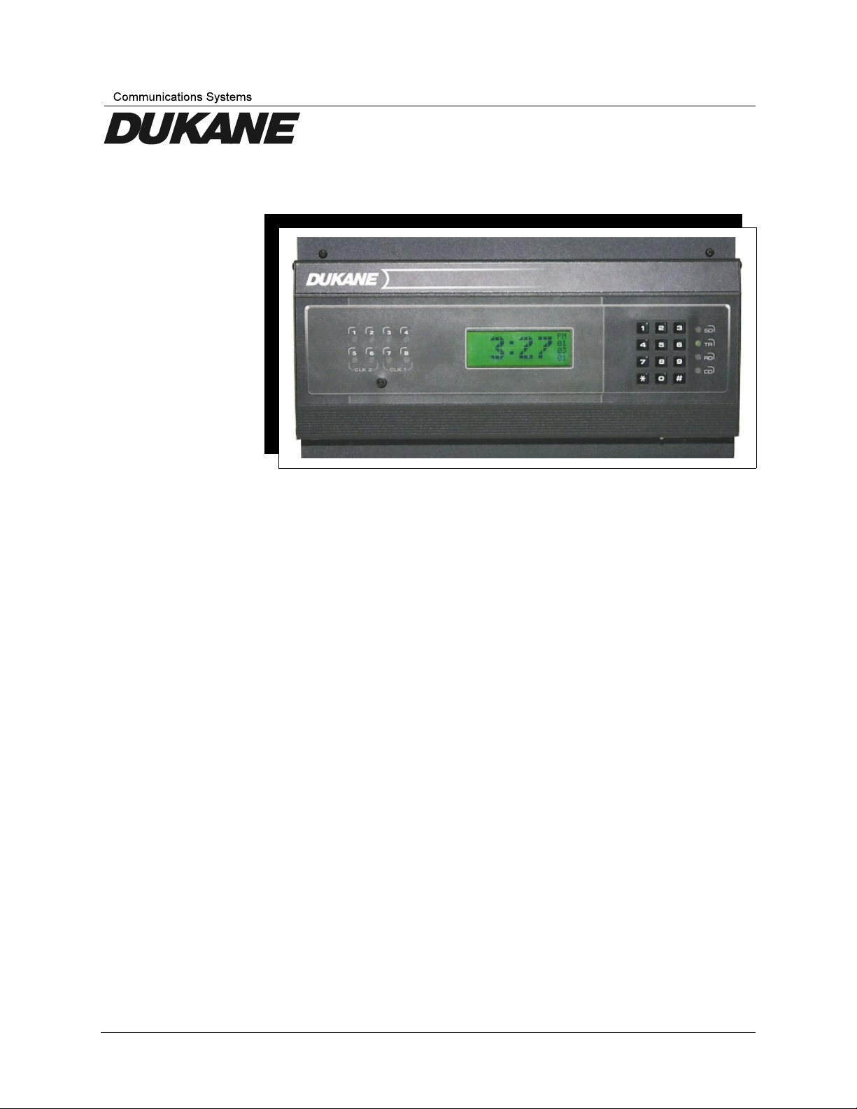
This installation manual covers the Model 24A715 and 24A715M Master Clocks. Both
clocks are installed and programmed in similar fashions. The main difference between
the clocks is the 24A715M is equipped with a built-in modem capable of communicating
with a PC, or for synchronizing with the NIST Atomic Clock. Both clocks have eight cir
cuits that can be programmed to ring bells or activate circuits for up to 99 seconds, and/or
synchronize the time on three types of clock systems (any two manufacturing brands of
clocks listed in Appendix B, plus compatible RS-485 time synchronization devices). You
can program up to 512 events to activate single or multiple circuits on a given day and
time. The 24A715M can also connect to a PC running Microsoft Windows
tional MasterLink™ software available from Lathem.
Unless otherwise specified, “master clock” refers to both units in this document.
The master clock can be programmed with these functions:
• User password
•
Date and time
•
Clock types to synchronize
•
Manual bell control (example: sounding a fire alarm)
•
Bell schedules (with events lasting up to 99 seconds)
Note: If a contact closurer in excess of 99 seconds is required, an external
latching relay will be required. This relay is not supplied by Dukane.
•
Dates when automatic schedule changes go into effect
•
Manual circuit disabling (example: for safety during maintenance)
•
Daylight saving time features
•
Instant bell schedule changes
•
Instant clock synchronization
•
Holiday schedules
•
Communications when using the master clock with an RS-485 network, modem
access, or the optional MasterLink programming software (available from Lathem)
Installation
®
using op
1
-
-
Parts List
Verify that the master clock came with these parts:
•
Master clock (ready to surface mount)
•
User guide (document number 427-07-00047)
•
Installation hardware kit with mounting screws and two extra cover screws
•
Two L-brackets used for rack mounting
•
Power supply box cover used for rack mounting
24A715/24A715M Master Clock Installation Manual
continued
1-1
Optional equipment (ordered separately from Lathem):
Connection cable if the power supply relay PCB is up to 8 feet (2.4 m) from the
•
display unit
Lathem MasterLink programming software to control the master clock from a PC
•
Standalone modem
•
Remote schedule selector switch
•
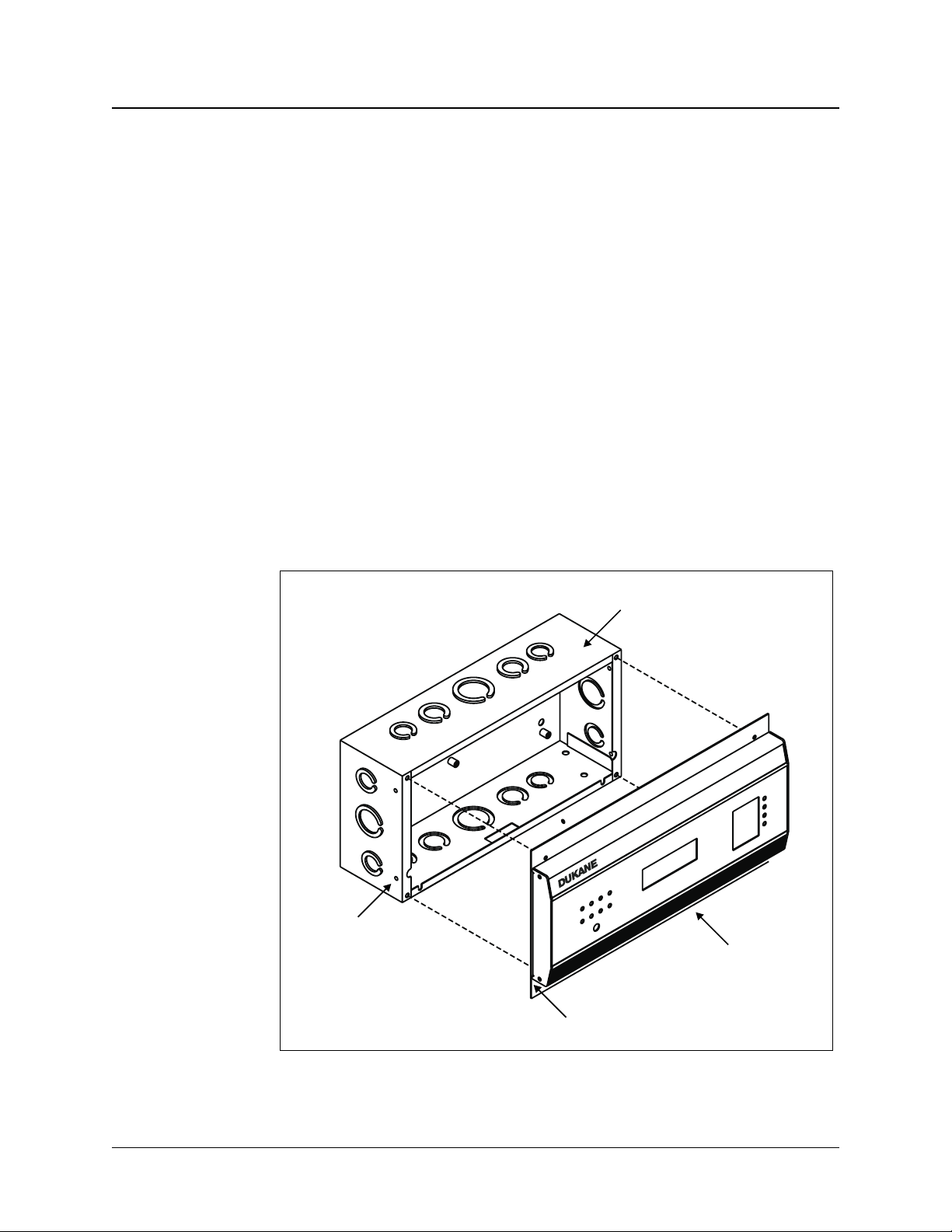
Mounting the Master Clock
The master clock is shipped ready to surface mount on a wall. It can also be semi-flush
mounted with the power supply recessed into the wall, or installed in a standard 19-inch
(48.3 cm) rack. See Figure 1-1 for wall mount assembly parts. The display unit can also
be hung on the wall with the power supply hidden in the floor or ceiling; contact Lathem
for details.
A qualified technician should install the master clock. The installation does not require
any special tools, but may require extra hardware, wire, or other materials as required by
local electrical codes.
Side Screw Hole
Power Supply Backbox
Display Unit
Wall Mount Plate
1-2
Figure 1-1
Master Clock Wall-Mount Assembly Parts
24A715/24A715M Master Clock Installation Manual

Surface Mounting
To surface mount the master clock:
1. Place the master clock on its back with the display unit facing up and the key pad to
the right.
2. Remove the two screws at the top of the display unit mounting plate.
3. Lift the display unit up and away from the backbox. Two rivets at the bottom of the
cover will prevent you from lifting it straight up.
4. Unplug the ribbon cable from the back of the display unit to disconnect it from the
power supply.
6. Making sure they are level, place two anchors 10 inches (25.4 cm) apart on the wall
where the clock is to be mounted. Use the appropriate anchors for the wall.
7. Screw two #8 screws into the wall anchors.
8. If needed, place two wall anchors 5 inches (12.7 cm) below the first two screws, to
accommodate the other two mounting screws.
9. Hang the power supply onto the top two screws using the keyholes on the back.
10. Screw two more #8 screws through the two holes at the bottom of the power supply
into the wall anchors.
11. Wire the clock. (See Wiring the Master Clock on page 1-8.)
12. Reconnect the ribbon cable.
13. Replace the display unit using the two screws removed in step 2.
24A715/24A715M Master Clock Installation Manual
1-3

Semi-Flush Mounting
The power supply portion of the master clock can be recessed into the wall, so that
the display unit is semi-flush with the wall. This should only be done by a qualified
technician.
To mount the master clock semi-flush:
1. Place the master clock on its back with the display unit facing up and the key pad to
the right.
2. Remove the two screws at the top of the display unit mounting plate.
3. Lift the display unit up and away from the backbox. Two rivets at the bottom of the
cover will prevent you from lifting it straight up.
4. Unplug the ribbon cable from the back of the display unit to disconnect the power
supply.
5. Set the display unit aside.
6. Prepare the clock’s position in the wall:
The power supply backbox measures 12 inches (30.5 cm) wide by 6 inches (15.2 cm)
high by 3-3/8 inches (8.6 cm) deep.
The wall mount cover measures 13 inches (33 cm) wide by 7 inches (17.8 cm) high
by 1-1/4 inch (3.2 cm) deep, and extends ½ inch (1.8 cm) around the backbox.
Cut a 12-1/4 inch (31.1 cm) by 6-1/4 inch (15.9 cm) hole in the wall between two
studs where you want to hang the master clock.
7. Cut two blocks of wood for filler and attach them to the studs.
8. Screw the power supply box to the blocks using the two holes on each side of the box.
9. Wire the clock. (See Wiring the Master Clock on page 1-8.)
10. Reconnect the ribbon cable.
11. Replace the display unit using the two screws removed in step 2.
1-4
24A715/24A715M Master Clock Installation Manual
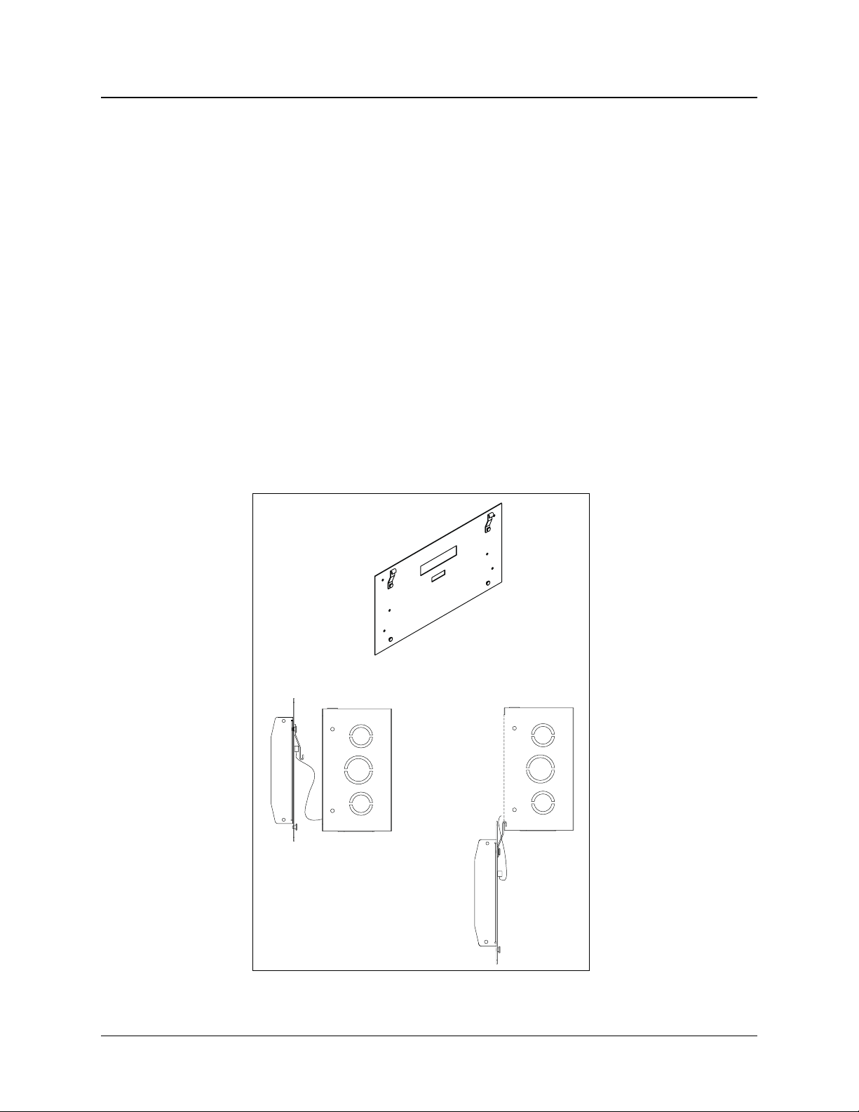
Using the Installer’s Hooks to Hang the Display Below the Backbox
When mounting the clock in either semi-flush or surface installations, the hooks on the
back of the display unit mounting plate can be used to hang the display unit below the
backbox to allow access for circuit testing and programming. See Figure 1-2.
To use the hooks:
1. Remove the two screws securing the display unit to the backbox.
2. Lift the unit up and away from the backbox, leaving the ribbon cable attached. Two
rivets at the bottom of the cover will prevent you from lifting it straight up.
3. If you have a semi-flush installation, remove the green communications connector
plug from the back of the display unit. This allows the unit to sit flat against the wall.
4. Swing up the two hooks on the back of the unit and hook them over the bottom edge
of the backbox. You now have access to the key pad for making program changes or
manually activating the circuits, and access to the relay and connector blocks inside
the backbox.
Hook Mounting the Display Unit
24A715/24A715M Master Clock Installation Manual
Figure 1-2
1-5

Rack Mounting
The two L-shaped brackets and the box cover supplied with the master clock can be used
to install it in a standard 19-inch (48.3 cm) rack. See Figure 1-3 on page 1-7.
To rack mount the clock:
1. Place the master clock on its back with the display unit facing up and the key pad to
the right.
2. Remove the two screws securing the display unit to the backbox.
3. Lift the display unit up and away from the backbox. Two rivets at the bottom of the
cover will prevent you from lifting it straight up.
4. Unplug the ribbon cable from the back of the display unit to disconnect the power
supply.
5. Detach the display unit from the wall mount plate by removing the four screws on the
back of the display unit. (IMPORTANT: Do not lose these screws. They are a specific
length so they do not interfere with the circuit board inside the display unit. Using any
other screws to attach the display unit to the case will void any warranty.)
6. Remove the rectangular knock out near the top of the power supply. See Figure 1-3
on page 1-7.
7. Using the four screws removed in step 5, attach the display unit to the bottom of the
power supply. To assist you, there are holes opposite the four screw holes where you
can fit a #1 Philips screwdriver with an 8-inch (20.3 cm) blade.
8. Reconnect the ribbon cable from the power supply to the display unit.
9. Remove the two screws from one side of the display unit, then use them to attach an
L bracket to the side of the unit. See Figure 1-3 on page 1-7. Repeat to attach the
other bracket to the other side.
10. Mount the unit in the rack.
11. Wire the clock before attaching the box cover. See Wiring the Master Clock on
page 1-8.
12. Attach the cover to the power supply using four 6-32 screws. Two of these screws
were removed from the display unit in step 2. The other two were supplied with the
clock.
1-6
24A715/24A715M Master Clock Installation Manual
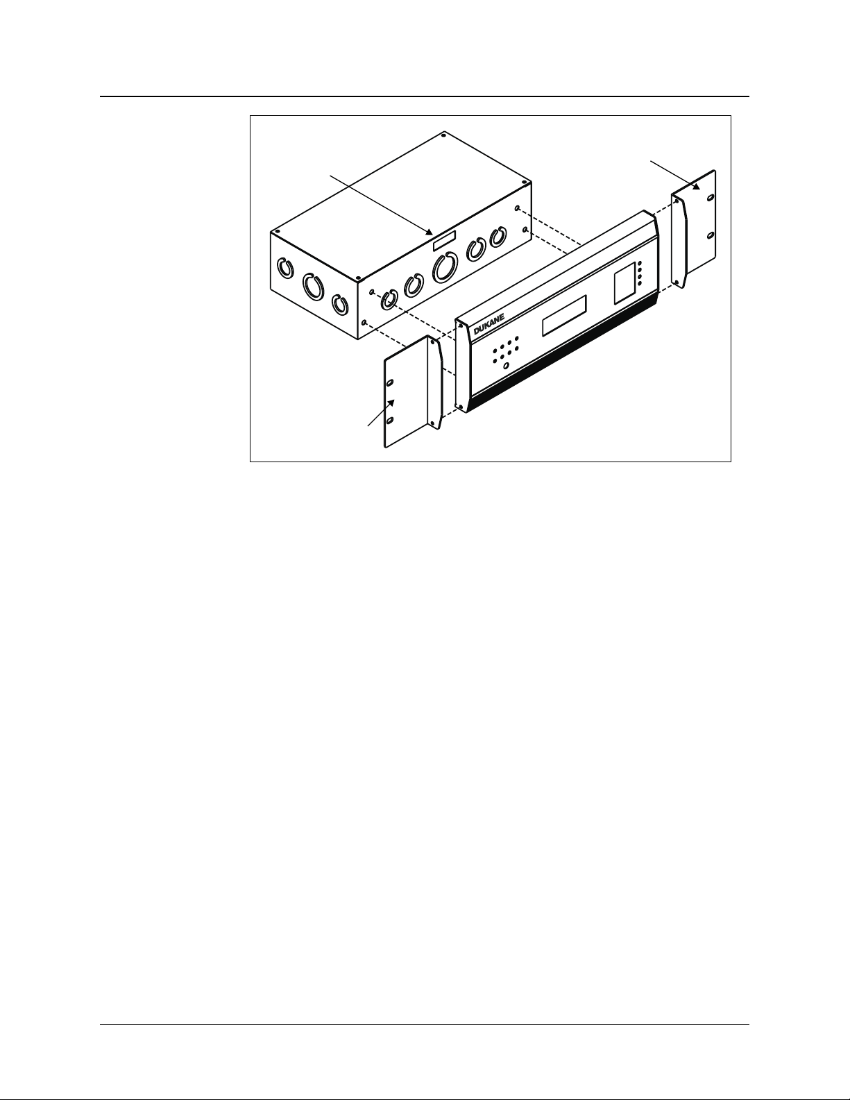
Rectangular
Knock Out
L Bracket
L Bracket
Figure 1-3
L Brackets for Rack Mounting
24A715/24A715M Master Clock Installation Manual
1-7
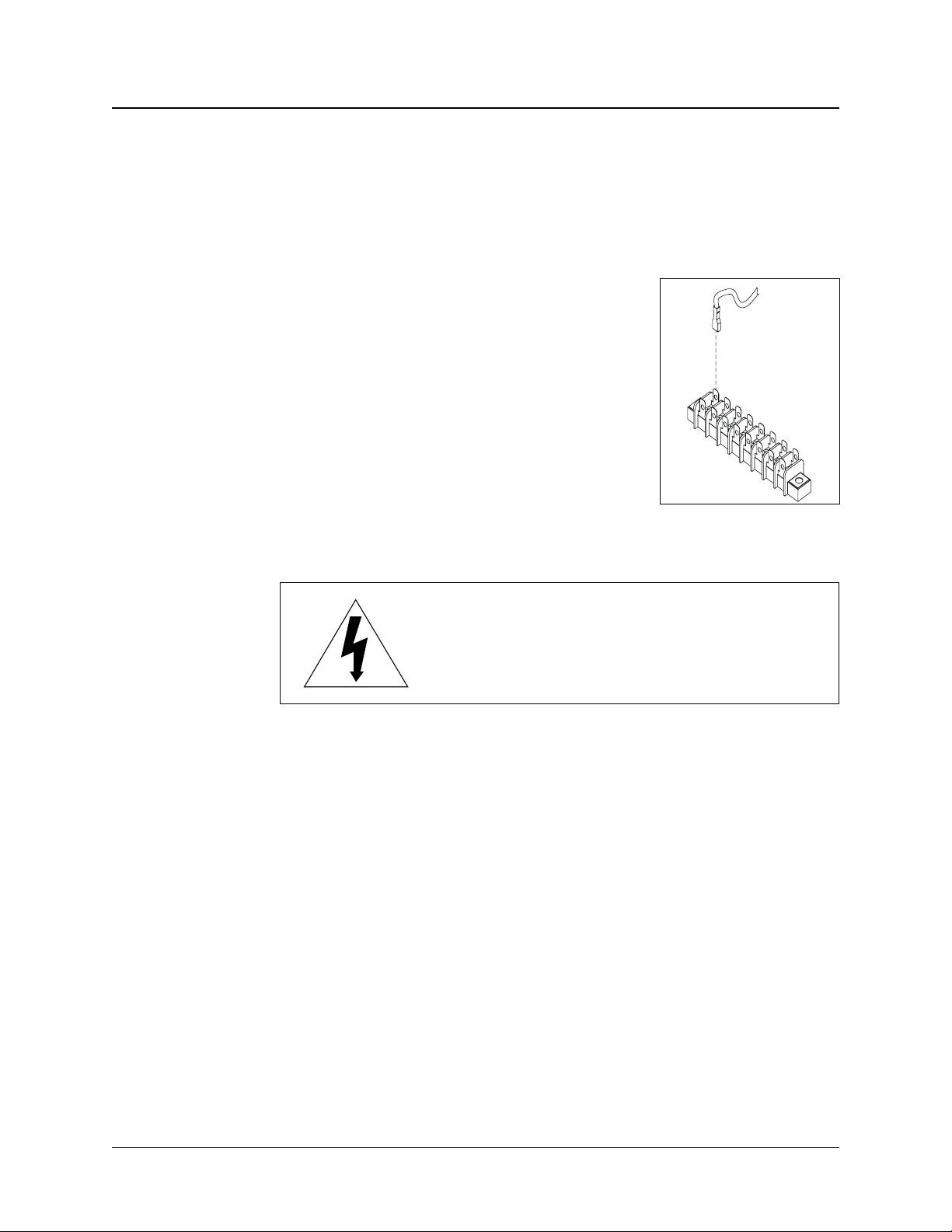
Wiring the Master Clock
This section provides instructions on wiring the power source, secondary clocks, and sig
naling devices to the master clock. It does not cover the connection of the optional
modem, a computer, any RS-485 devices, and a power source for the optional remove
schedule selector. Instructions for those devices are provided in Appendix C.
Stranded wire is recommended for use inside the power
supply box, as it allows a firm connection to the quick
connect terminals. There is also less chance of stranded
wires interfering with the components on the relay board.
If solid wire must be used, join the stranded wire to the
solid wire in another box.
The master clock is supplied with quick connects. These
should be attached to the wires as necessary so that the
wiring can be connected to the terminal blocks as shown
in Figure 1-4.
Figure 1-4
Plugging Quick Connects
into the Terminal Block
—WARNING—
Failure to properly connect the ground wire
can increase interference and cause
unsafe operating conditions.
-
1-8
Wiring Procedure
Figure 1-5 on page 1-9 shows terminal blocks P1 through P4, located on the PCB in the
power supply backbox. Follow the steps below the figure to wire the clocks, power
source, and signaling devices to the master clock.
Notes:
•
Circuits CKT1 through CKT4 designate bell controls. Circuit pairs CKT5/CKT6
and CKT7/CKT8 can function as clock synchronization circuits or as bell controls.
•
MOVs (Metal-Oxide Varistors) protect all relay contacts.
•
Voltage-select jumpers connect to terminal block P4 for 120Vac operation. For
clocks that must run at 220/240Vac, remove the 120V jumpers and install one
jumper wire for the 240V selection. The system will automatically adjust for oper
ation at 50Hz or 60Hz at either voltage. Also see Terminal Block P4 on page C-2.
•
Some clock setups may require external diodes or MOVs. See the wiring diagram
for your type clock (see Appendix B).
-
24A715/24A715M Master Clock Installation Manual
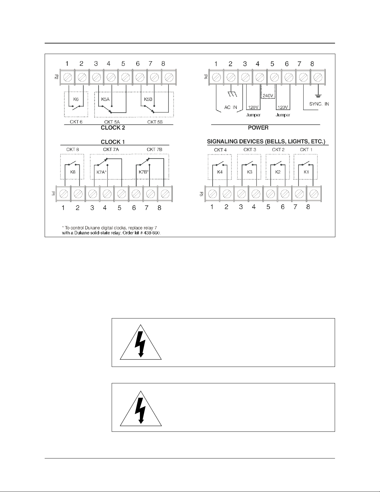
Figure 1-5
Master Clock Terminal Blocks
1. Wire the power source to P4 as shown in either Figure C-1 or C-2 on page C-2.
Note:
The master clock is shipped set up for 120Vac operation. To wire it for 220/240Vac,
change the jumper settings as shown in Figure C-2.
—WARNING—
DO NOT turn on AC power, and keep the
power/relay unit’s toggle switch OFF until you
complete the rest of the wiring in this section.
—WARNING—
Applying 220/240Vac power to a system not
set up for that voltage level can severely
damage the electronic parts.
24A715/24A715M Master Clock Installation Manual
1-9

2. Wire the secondary clocks to P1 and/or to P2. See Wiring Secondary Clocks on
page B-2 for complete instructions.
Note:
You may need to add external metal-oxide varistors (MOVs) or diodes to synchronize
a specific clock type. See the clock wiring diagrams in Appendix B.
3. Wire the signaling devices to P3. See Typical Signal Device Wiring on page C-3.
Note:
If the master clock is not connected to any secondary clocks, signaling devices can be
wired to P1 and P2.
4. Although the master clock is fused internally to protect its electronics, the incoming
AC line must also be fused as required by your local electrical code. Dukane recom
mends connecting the unit to a dedicated 10-amp circuit.
5. Turn the toggle switch in the power supply to the ON position.
6. Complete any mounting steps in the previous section, Mounting the Master Clock
on page 1-2.
-
Synchronizing Non-Compatible Clocks by External Pulse
The master clock can synchronize to other systems if necessary. For example, you have a
non-compatible time clock that cannot be synchronized by the master clock, but it has a
built-in bell ringer. By shorting terminals 7 and 8 on terminal block P4, or terminals 6
and 7 of the communications terminal on the back of the display unit, the master clock
will immediately reset to 00:00 (midnight). If you can program the other device to close
its circuit at 00:00 (midnight) then the two systems will remain reasonably in sync.
—WARNING—
DO NOT apply power to the external
pulse-sync terminals. Simply close
the circuit for 1–5 seconds.
1-10
24A715/24A715M Master Clock Installation Manual
Section
Setting Up the Master Clock
Once the master clock is installed, it is ready for programming. This chapter covers the
programming instructions needed to set the master clock for operations.
Note:
To completely clear the clock of all settings and reset the master clock to its factoryshipped configuration, press the following number sequence on the master clock key
pad: 355379768274. This clears all programmed schedules and reinitializes the
master clock.
Programming Relays
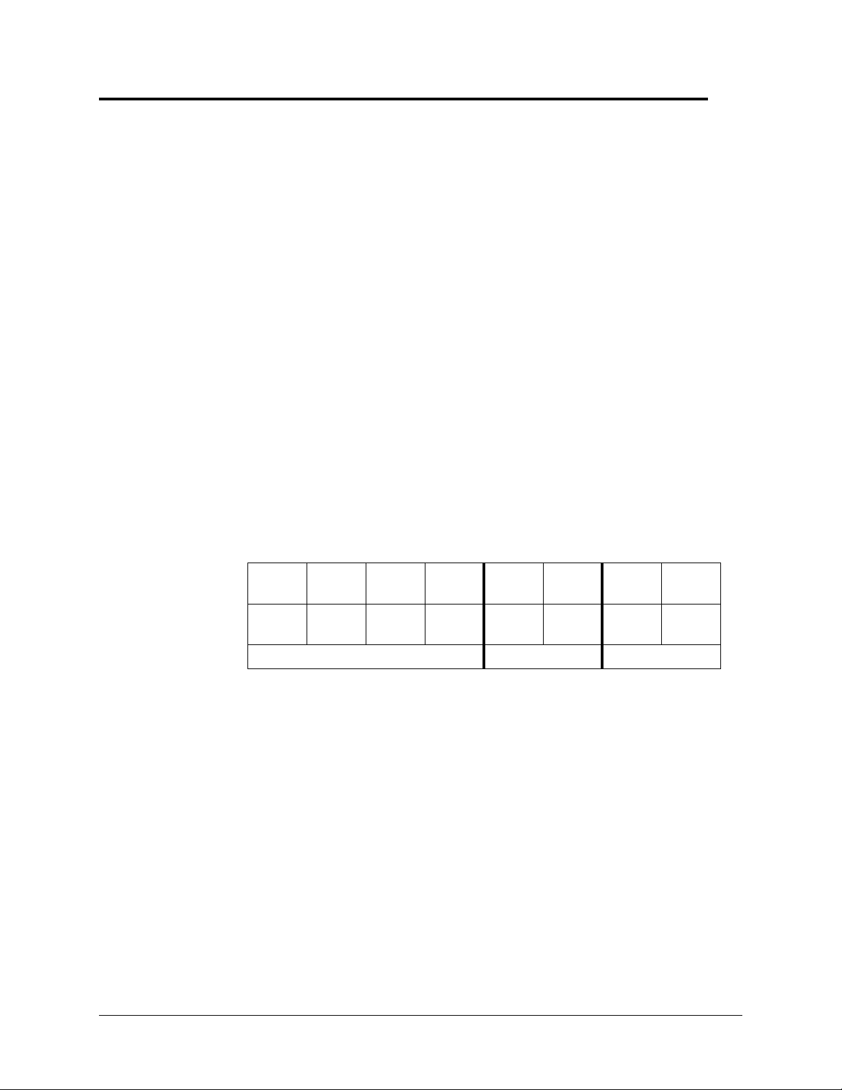
If the master clock will control one type of secondary clock, relays #7 and #8 on terminal
block P1 are used for this purpose. If the master clock will control a second clock type,
relays #5 and #6 on terminal block P2 are used for those clocks. See Table 2-1.
Configuration
2
Bell
Zone #1
Relay#1Relay2#Relay#3Relay#4Relay#5Relay#6Relay#7Relay
Here are some possible ways to program the master clock relays:
•
Eight bell zones that can last from 1 to 99 seconds. Use this setup if the master clock
will not be used to synchronize secondary clocks. (Note: The maximum closure time
provided by this master clock is 99 seconds. Closures longer than 99 seconds will re
quire an external latching relay. This is not provided by Dukane.)
•
Six bell zones and one wall clock synchronization control. Use this setup if the master
clock will only synchronize one type of clock in one string.
•
Four bell zones and two wall clock synchronization controls. Use this setup if the mas
ter clock will synchronize two clock types, or if there are two strings of clocks
(typically 20 to 35 clocks to a string).
Bell
Zone #2
Bell
Zone #3
Bell
Zone #4
Table 2-1
Relay Usage
Bell
Zone #5
Clock Sync #2 Clock Sync #1
Bell
Zone #6
Bell
Zone #7
Bell
Zone #8
#8
-
-
24A715/24A715M Master Clock Installation Manual
2-1

Programming Functions
This section explains how to put the master clock in program mode and configure the
necessary functions to get the master clock running. For definitions of all functions, key
pad commands, and the bell test, see Section 3—Function List.
The master clock is normally in clock mode, displaying the date and time. To access pro
gram mode, press [#] on the key pad. Pressing [*] stops programming so you can re-enter
a setting or quit.
Entering the Password
The administrative password provides access to both advanced functions and user functions.
The user password only provides access to user functions.
The factory-programmed user password is 000000, and can be changed (see page 3-6).
User passwords are explained further in the Master Clock User Guide, document
427-07-00047.
The factory-programmed administrative password is 332537, or DEALER (as spelled out
on a telephone key pad). It cannot be changed.
Note:
To keep the administrative functions secure, only give this guide to authorized personnel.
The following shows the key sequence to enter the password, and the resulting clock
display:
-
Administrative Password: User Password:
Press Display Press Display
[#] SELECT FUNCTION CODE [#] SELECT FUNCTION CODE
[0] [0] = ENTER PASSWORD [0] [0] = ENTER PASSWORD
[#] PASSWORD: 000000 [#] PASSWORD: 000000
[3][3][2][5][3][7] PASSWORD: 332537 [user password] PASSWORD: NNNNNN
[#] ADMINISTRATOR [#] PASSWORD ACCEPTED
PASSWORD ACCEPTED
The display returns to clock mode (the time and date) after a few seconds.
Notes:
A password expires after approximately five minutes. If the master clock starts block
ing access to programming functions, re-enter the password.
To manually expire a password, see Securing the Setup on page 2-9.
2-2
24A715/24A715M Master Clock Installation Manual
-
 Loading...