


 Loading...
XPress DR+
User Guide
Part Number 900-422
Revision B October 2006
Copyright & Trademark
© 2006, Lantronix. All rights reserved. No part of the contents of this book may be transmitted or reproduced in any form or by any means without the written permission of Lantronix. Printed in the United States of America.
Ethernet is a trademark of XEROX Corporation. UNIX is a registered trademark of The Open Group. Windows 95, Windows 98, Windows 2000, and Windows NT are trademarks of Microsoft Corp. Netscape is a trademark of Netscape Communications Corporation.
Contacts
Lantronix Corporate Headquarters
15353 Barranca Parkway
Irvine, CA 92618, USA
Phone: 949-453-3990
Fax: 949-453-3995
Technical Support
Online: www.lantronix.com/support
Sales Offices
For a current list of our domestic and international sales offices, go to the Lantronix web site at www.lantronix.com/about/contact .
Disclaimer & Revisions
Operation of this equipment in a residential area is likely to cause interference, in which case the user, at his or her own expense, will be required to take whatever measures may be required to correct the interference.
Attention: This product has been designed to comply with the limits for a Class A digital device pursuant to Part 15 of FCC Rules. These limits are designed to provide reasonable protection against such interference when operating in a commercial environment. This equipment generates, uses, and can radiate radio frequency energy, and if not installed and used in accordance with this guide, may cause harmful interference to radio communications.
This Class A digital apparatus complies with Canadian ICES-003.
Cet appareil num′erique de la classe A est conforme ′a la norme NMB-003 du
Canada.
Changes or modifications to this device not explicitly approved by Lantronix will void the user's authority to operate this device.
The information in this guide may change without notice. The manufacturer assumes no responsibility for any errors that may appear in this guide.
|
Date |
Rev. |
Comments |
|
|
3/06 |
A |
Initial document |
|
|
10/06 |
B |
Added description of wireless functionality |
|
XPress DR+ User Guide |
2 |
Contents
Chapter 1: Using This Guide |
10 |
Purpose and Audience_______________________________________________ 10 Summary of Chapters _______________________________________________ 10 Additional Documentation ____________________________________________ 11
Chapter 2: Introduction |
12 |
Product Description _________________________________________________ 12 Industrial Automation Protocols ________________________________________ 14 Network Protocols (Serial Tunneling)____________________________________ 14 XPress DR+ Application Examples _____________________________________ 15 Addresses and Port Numbers _________________________________________ 16
Hardware Address ______________________________________________________ 16
IP Address ____________________________________________________________ 16
Port Numbers __________________________________________________________ 16
Configuration Methods_______________________________________________ 17
Chapter 3: Installation and Hardware |
18 |
What's in the Box? __________________________________________________ 18
What Must the User Provide? _____________________________________________ 18
Physically Connecting the XPress DR+ __________________________________ 18 XPress DR+ Front Panel _____________________________________________ 19 Serial Interface_____________________________________________________ 20
Screw Terminal Serial Connectors__________________________________________ 21
9-Pin RS-232 to Serial RJ45 Cable (P/N 500-103) _____________________________ 22
Ethernet Interface __________________________________________________ 23
Multi-Drop Ethernet Connections ___________________________________________ 24
Power Requirements ________________________________________________ 24 Reset Switch ______________________________________________________ 24 LEDs ____________________________________________________________ 25 Dimensions _______________________________________________________ 26 Wall Mount Bracket _________________________________________________ 27 Product Information Label ____________________________________________ 27
Chapter 4: XPress DR+W |
28 |
Application Examples________________________________________________ 28
Serial Tunneling – Network _______________________________________________ 28
XPress DR+ User Guide |
3 |
Contents
Ad Hoc Network ________________________________________________________ 29
Serial Tunneling – Infrastructure ___________________________________________ 29
Ad Hoc XPress DR+W Connection _________________________________________ 30
Physically Connecting the XPress DR+W ________________________________ 30 Front Panel Description ______________________________________________ 31 LEDs ____________________________________________________________ 32 Required Information for Initial Configuration______________________________ 32
Hardware Address ______________________________________________________ 32
IP Address ____________________________________________________________ 32
WLAN Settings _________________________________________________________ 33
Installing the XPress DR+W for Initial Configuration ________________________ 33 Server Configuration (Option 0) ________________________________________ 33
Network Mode (XPress DR+W only) ________________________________________ 34 IP Address ____________________________________________________________ 34 Set Gateway IP Address _________________________________________________ 34 Netmask: Number of Bits for Host Part ______________________________________ 35 Change Telnet Configuration Password _____________________________________ 35 Change DHCP Device Name: _____________________________________________ 35
WLAN Configuration (Option 4) ________________________________________ 35
Topology______________________________________________________________ 36 Network Name (SSID) ___________________________________________________ 36 Adhoc Network Channel _________________________________________________ 36 WEP _________________________________________________________________ 37 WPA _________________________________________________________________ 38 WPA2/802.11i _________________________________________________________ 39 Fixed or Automatic Data Rate _____________________________________________ 39 Transmission Data Rate__________________________________________________ 40
Next Steps ________________________________________________________ 40
Chapter 5: Using DeviceInstaller |
41 |
Installing DeviceInstaller _____________________________________________ 41 Assigning an IP Address _____________________________________________ 41 Accessing the XPress DR+ Using DeviceInstaller __________________________ 42 Viewing the Current Configuration ______________________________________ 42
Chapter 6: Configuration Using Web Manager |
45 |
Accessing XPress DR+ Using DeviceInstaller _____________________________ 45 Network Configuration _______________________________________________ 46
Automatic IP Address Configuration ________________________________________ 47
Static IP Address Configuration ____________________________________________ 48
XPress DR+ User Guide |
4 |
Contents
Server Configuration ________________________________________________ 48 Host List Configuration_______________________________________________ 50 Channel Configuration _______________________________________________ 51
Serial Settings _________________________________________________________ 51
Connection Settings - TCP________________________________________________ 54
Connection Settings - UDP _______________________________________________ 56
WLAN Configuration (XPress DR+W only) _______________________________ 58 Applying Settings ___________________________________________________ 62 Applying Factory Defaults ____________________________________________ 62
Chapter 7: Configuration Using Telnet or Serial Port (Setup Mode) |
63 |
Accessing Setup Mode ______________________________________________ 63
Telnet Connection ______________________________________________________ 63
Serial Port Connection ___________________________________________________ 64
Exiting Setup Mode _________________________________________________ 65
Chapter 8: Setup Mode: Server Configuration |
66 |
Server Configuration (Option 0) ________________________________________ 66
Network Mode (XPress DR+W only) ________________________________________ 66 IP Address ____________________________________________________________ 66 Set Gateway IP Address _________________________________________________ 67 Netmask: Number of Bits for Host Part ______________________________________ 67 Change Telnet Configuration Password _____________________________________ 68
DHCP Name ______________________________________________________ 68
Chapter 9: Setup Mode: Channel Configuration |
69 |
Channel 1 (Option 1) and Channel 2 (Option 2) ___________________________ 69 Baudrate _________________________________________________________ 69 I/F (Interface) Mode _________________________________________________ 70 Flow _____________________________________________________________ 71 Port Number_______________________________________________________ 71 Connect Mode _____________________________________________________ 72
a)Incoming Connection __________________________________________________ 73
b)Response ___________________________________________________________ 73
c)Active Startup________________________________________________________ 73
d)Datagram Type ______________________________________________________ 75
e)Modem Mode ________________________________________________________ 75
Send the Escape Sequence (+++) in Modem Mode ________________________ 78 Auto Increment Source Port___________________________________________ 78 Remote IP Address _________________________________________________ 78
XPress DR+ User Guide |
5 |
Contents
Remote Port_______________________________________________________ 79 DisConnMode _____________________________________________________ 79 Flush Mode (Buffer Flushing)__________________________________________ 80 Pack Control ______________________________________________________ 80
Packing Interval ________________________________________________________ 81
Trailing Characters______________________________________________________ 81
Send Characters _______________________________________________________ 81
DisConnTime (Inactivity Timeout) ______________________________________ 81 Send Characters ___________________________________________________ 82 Telnet Terminal Type ________________________________________________ 82 Channel (Port) Password_____________________________________________ 82 WLAN Settings (XPress DR+W Only) ___________________________________ 82
Topology______________________________________________________________ 83 Network Name (SSID) ___________________________________________________ 83 Adhoc Network Channel _________________________________________________ 83 WEP _________________________________________________________________ 84 WPA _________________________________________________________________ 85 WPA2/802.11i _________________________________________________________ 86 Fixed or Automatic Data Rate _____________________________________________ 86 Transmission Data Rate__________________________________________________ 86 Enable Power Management_______________________________________________ 87
Chapter 10: Setup Mode: Advanced Settings |
88 |
Expert Settings (Option 5) ____________________________________________ 88
TCP Keepalive time in seconds ____________________________________________ 88 ARP Cache timeout in seconds ____________________________________________ 88 Disable Monitor Mode at bootup ___________________________________________ 88 HTTP Port Number______________________________________________________ 89 MTU Size _____________________________________________________________ 89 Enable alternate MAC ___________________________________________________ 89
Security Settings (Option 6) ___________________________________________ 89
Disable SNMP _________________________________________________________ 90 SNMP Community Name _________________________________________________ 90 Disable Telnet Setup ____________________________________________________ 90 Disable TFTP Firmware Upgrade __________________________________________ 90 Disable Port 77FE (Hex) _________________________________________________ 90 Disable Web Server _____________________________________________________ 91 Disable Web Setup______________________________________________________ 91 Disable ECHO Ports_____________________________________________________ 91
XPress DR+ User Guide |
6 |
Contents
Enable Enhanced Password ______________________________________________ 91
Default Settings (Option 7)____________________________________________ 91
Channel 1 and Channel 2 Configuration Settings ______________________________ 91 Expert Settings _________________________________________________________ 92 Security Settings _______________________________________________________ 92 WLAN Settings (XPress DR+W only)________________________________________ 92
Chapter 11: Firmware Upgrades |
93 |
Obtaining Firmware _________________________________________________ 93 Reloading Firmware_________________________________________________ 93
Using TFTP: Graphical User Interface _______________________________________ 93 Using TFTP: Command Line Interface_______________________________________ 94 Recovering the Firmware Using the Serial Port and DeviceInstaller ________________ 94
Chapter 12: Monitor Mode |
96 |
Entering Monitor Mode Using the Serial Port__________________________________ 96 Entering Monitor Mode Using the Network Port________________________________ 96 Monitor Mode Commands ________________________________________________ 96
Chapter 13: Troubleshooting and Technical Support |
99 |
Problems and Error Messages ________________________________________ 99 Technical Support _________________________________________________ 102
Appendix A: Technical Specifications |
103 |
Appendix B: Lantronix Cables and Adapters |
105 |
Appendix C: Alternative Methods of Assigning an IP Address |
106 |
DHCP _______________________________________________________________ 106
AutoIP_______________________________________________________________ 106
BOOTP______________________________________________________________ 107
ARP and Telnet _______________________________________________________ 107
Appendix D: Binary to Hexadecimal Conversions |
108 |
Converting Binary to Hexadecimal_____________________________________ 108
Conversion Table ______________________________________________________ 108
Scientific Calculator ____________________________________________________ 108
Appendix E: Compliance Information |
110 |
Declaration of Conformity ___________________________________________ 110 XPress DR+W Regulatory Information _________________________________ 112
USA Federal Communications Commission (FCC) Notice ______________________ 112 Canada – Industry Canada Notice _________________________________________ 112 Europe – R&TTE Directive 99/5/EC, Wireless Notice __________________________ 113
XPress DR+ User Guide |
7 |
Contents
Australia & New Zealand – Wireless Notice__________________________________ 114
Appendix F: Warranty |
115 |
Index |
116 |
Figures
Figure 2-1. XPress DR+ (Front) .......................................................................... |
13 |
Figure 2-2. Example of Serial Tunneling ............................................................. |
15 |
Figure 2-3. Example of Cascading Multiple XPress DR+ Units .......................... |
16 |
Figure 2-4. Sample Hardware Address ............................................................... |
16 |
Figure 3-1. Typical Configuration ........................................................................ |
19 |
Figure 3-2. Front of XPress DR+......................................................................... |
20 |
Figure 3-4. Screw Terminal Ports........................................................................ |
21 |
Figure 3-5. Termination Resistor for 2-Wire Connection..................................... |
22 |
Figure 3-6. Lantronix P/N 500-103 RJ45-DB9F Serial Cable Pinout .................. |
22 |
Figure 3-7. Multi-Drop Ethernet Connections...................................................... |
24 |
Figure 3-8. Reset Switch ..................................................................................... |
25 |
Figure 3-9. LEDs on the XPress DR ................................................................... |
25 |
Figure 3-10. Dimensions ..................................................................................... |
26 |
Figure 3-11. Wall Mount Bracket......................................................................... |
27 |
Figure 3-12. Product Label.................................................................................. |
27 |
Figure 4-1. Serial Tunneling Infrastructure Network Example ............................ |
28 |
Figure 4-2. Ad Hoc Network Example ................................................................. |
29 |
Figure 4-3. Serial Tunneling Infrastructure Example........................................... |
29 |
Figure 4-4. Direct XPress DR+W - toXPress DR+W Connection ..................... |
30 |
Figure 4-5. Typical XPress DR+W Configuration................................................ |
31 |
Figure 4-6. XPress DR+W Front Panel Layout ................................................. |
31 |
Figure 4-7. Network Mode................................................................................... |
34 |
Figure 4-8. Server Settings.................................................................................. |
34 |
Figure 6-1. Lantronix Web Manager.................................................................... |
46 |
Figure 6-2. Network Settings............................................................................... |
47 |
Figure 6-3. Server Settings.................................................................................. |
49 |
Figure 6-4. Hostlist Settings ................................................................................ |
50 |
Figure 6-5. Channel Serial Settings .................................................................... |
52 |
Figure 6-6. TCP Connection Settings.................................................................. |
54 |
Figure 6-7. UDP Connection Settings ................................................................. |
57 |
Figure 6-8. WLAN Settings – Ad Hoc Network Type .......................................... |
59 |
Figure 6-9. WLAN Settings – Infrastructure Network Type ................................. |
60 |
Figure 7-1. MAC Address.................................................................................... |
64 |
Figure 7-2. Setup Menu Options ......................................................................... |
64 |
Figure 8-1. Network Mode................................................................................... |
66 |
Figure 8-2. Server Settings.................................................................................. |
66 |
Figure 9-1. Serial Port Parameters...................................................................... |
69 |
Figure 9-2. Manual Connection Address Example.............................................. |
74 |
Figure 9-3. Hostlist Option................................................................................... |
75 |
Figure 10-1. Expert Settings................................................................................ |
88 |
Figure 10-2. Security Settings ............................................................................. |
89 |
Figure 11-1. TFTP Window ................................................................................. |
94 |
Figure 12-1. Accessing Monitor Mode................................................................. |
96 |
XPress DR+ User Guide |
8 |
Contents
Tables
Table 3-1. RJ45 Serial Connector Pinouts .......................................................... |
21 |
Table 3-2. Serial Screw Terminal Pinout for RS422 (4-Wire) ............................. |
21 |
Table 3-3. Serial Screw Terminal Pinout for RS485 (2-Wire) ............................. |
21 |
Table 3-4. Ethernet Interface Signals.................................................................. |
23 |
Table 3-5.Typical RJ45 Connector...................................................................... |
23 |
Table 3-6. XPress DR+ LED Functions............................................................... |
26 |
Table 4-1. XPress DR+W LED Functions ........................................................... |
32 |
Table 4-2. BootP/DHCP/AutoIP options.............................................................. |
34 |
Table 4-3. Standard IP Network Netmasks......................................................... |
35 |
Table 5-1. Viewing Current Settings.................................................................... |
43 |
Table 8-1. BootP/DHCP/AutoIP options.............................................................. |
67 |
Table 8-2. Standard IP Network Netmasks......................................................... |
67 |
Table 9-1. Interface Mode Options...................................................................... |
70 |
Table 9-2. Common Interface Mode Settings...................................................... |
70 |
Table 9-3. Flow Control Options.......................................................................... |
71 |
Table 9-4. Reserved Port Numbers..................................................................... |
71 |
Table 9-5. Connect Mode Options ...................................................................... |
72 |
Table 9-6. Modem Mode Messages.................................................................... |
76 |
Table 9-7. Modem Mode Commands.................................................................. |
77 |
Table 9-8. Disconnect Mode Options .................................................................. |
79 |
Table 9-9. Flush Mode Options ........................................................................... |
80 |
Table 9-10. Pack Control Options ....................................................................... |
80 |
Table 11-1. Firmware Files.................................................................................. |
93 |
Table 12-1. Monitor Mode Commands................................................................ |
97 |
Table 13-1. Problems and Error Messages......................................................... |
99 |
Table 13-2. XPress DR+ and XPress DR+W Specifications............................. |
103 |
Table 13-3. XPress DR+W Wireless Specifications.......................................... |
104 |
Table 13-4. Electromagnetic Emissions and Immunity – XPress DR+ ............. |
110 |
Table 13-5. Electromagnetic Emissions and Immunity – XPress DR+W.......... |
111 |
XPress DR+ User Guide |
9 |
Chapter 1: Using This Guide
Purpose and Audience
This manual describes the Lantronix XPress DR+ and XPress DR+W device servers. These device servers are members of the XPress family that work with Industrial Automation Protocols. The XPress DR+ W has wireless as well as wired capability.
This guide provides the information needed to configure, use, and update the XPress DR+ device servers. It is for system administrators and those responsible for installing and maintaining these device servers.
Summary of Chapters
The remaining chapters in this guide include:
|
Chapter |
Description |
|
|
|
|
|
|
Chapter 2: Introduction |
Describes the main features of the XPress DR+ and the |
|
|
|
protocols it supports. |
|
|
|
|
|
|
Chapter 3: Installation and |
Describes the unit's interfaces and power requirements. |
|
|
Hardware |
Provides instructions for physically connecting the unit. |
|
|
|
|
|
|
Chapter 4: XPress DR+W |
Describes the XPress DR+W and how to install and |
|
|
|
configure the unit initially. |
|
|
|
|
|
|
Chapter 5: Using DeviceInstaller |
Provides information for getting your unit up and running, |
|
|
|
using DeviceInstaller to assign an IP address. |
|
|
|
|
|
|
Chapter 6: Configuration Using |
Details using the Web Manager to set parameters such |
|
|
Web Manager |
as port and server properties. |
|
|
Chapter 7: Configuration Using |
Provides instructions for accessing Setup Mode |
|
|
Telnet or Serial Port (Setup |
(command line interface) using a Telnet connection |
|
|
Mode) |
through the network or a terminal or terminal emulation |
|
|
|
program through the serial port. |
|
|
|
|
|
|
Chapter 8: Setup Mode: Server |
Details the network (server) settings |
|
|
Configuration |
|
|
|
|
|
|
|
Chapter 9: Setup Mode: |
Details the serial port settings. |
|
|
Channel Configuration |
|
|
|
|
|
|
|
Chapter 10: Setup Mode: |
Details email, expert, and security settings and explains |
|
|
Advanced Settings |
how to reset the unit to factory default values. |
|
|
|
|
|
|
Chapter 11: Firmware Upgrades |
Provides instructions for obtaining the latest firmware and |
|
|
|
updating the XPress DR+. |
|
|
|
|
|
|
Chapter 12: Monitor Mode |
Provides instructions for accessing and using the |
|
|
|
command line interface for monitoring the network and |
|
|
|
diagnosing problems. |
|
|
|
|
|
|
|
|
|
XPress DR+ User Guide |
10 |
|
|
|
Chapter 1: Using This Guide |
|
|
|
|
Chapter 13: Troubleshooting |
Describes common problems and error messages and |
|
and Technical Support |
how to contact Lantronix Technical Support. |
|
|
|
|
Appendix A: Technical |
Lists technical information about the unit. |
|
Specifications |
|
|
|
|
|
Appendix C: Alternative |
Describes other ways to assign an IP address, for |
|
Methods of Assigning an IP |
example, though ARP and Telnet. |
|
Address |
|
|
|
|
|
Appendix D: Binary to |
Provides instructions for converting binary numbers to |
|
Hexadecimal Conversions |
hexadecimals. |
|
|
|
|
Appendix E: Compliance |
Provides the Declaration of Conformity and other |
|
Information |
regulatory information. |
|
|
|
|
Appendix F: Warranty |
|
|
|
|
|
Additional Documentation
The following guides are available on the product CD and the Lantronix web site (www.lantronix.com).
XPress DR+ Quick Start or XPress |
Provides the steps for getting the XPress DR+ or |
DR+W Quick Start |
XPress DR+W up and running. |
Com Port Redirector Quick Start |
Provides information on using the Windows-based |
and Com Port Redirector Online |
utility to create a virtual com port. |
Help |
|
DeviceInstaller Online Help |
Provides information on using DeviceInstaller to |
|
locate Lantronix devices on the network and |
|
configure IP addresses. |
"Live" tutorials on the Lantronix |
Explain and demonstrate assigning an IP address |
Web Site |
and setting up the unit and the Redirector. See |
|
http://ts.lantronix.com/tutorials.html. |
|
Note: The instructions for the UDS products apply |
|
to the XPress DR+ as well. |
|
|
Protocol documentation |
Provides guides for the protocols, such as Modbus |
|
Bridge and Multi-Master DF1, which you can load |
|
on the XPress DR+. |
XPress DR+ User Guide |
11 |
Chapter 2: Introduction
This chapter provides basic information about the wired and wireless versions of the XPress DR+. The wireless version has two modes of operation: wireless and wired. In wired mode, the wireless functionality is not used, and the unit behaves identically to the wired XPress DR+. In wireless mode, the unit's behavior is wireless to serial, and the Ethernet ports are not functional.
Unless otherwise noted, information in this User Guide applies to both versions of the product. Information specific to the wireless version of the XPress DR+ unit is in
Chapter 4: XPress DR+W.
Note: In this User Guide we sometimes refer to the XPress DR+W as "the wireless unit" or the "wireless device server."
Product Description
The Lantronix XPress DR+ Industrial Device Server is a robust, feature-rich, and cost effective way to network-enable equipment in an industrial automation environment. The XPress DR+ provides two serial ports, two switched Ethernet ports, a wide power input range, and expanded environmental specifications, making it an ideal solution
for connecting multiple asynchronous RS232, RS422, or RS485 serial devices to an Ethernet network.
The internal two-port Ethernet switch allows the XPress DR+ to cascade connections from a single network drop to another Ethernet device or from one XPress DR+ to another and another, and so on. By leveraging a single network drop to connect multiple devices, the XPress DR+ greatly reduces device connectivity costs, reduces cabling cost and simplifies system changes and device moves.
By encapsulating serial data and transporting it over Ethernet, the XPress DR+ allows virtual serial links over Ethernet and IP (TCP/IP, UDP/IP) networks. As a result, you can extend limited distance, point-to-point, direct serial connections within the plant, throughout the facility, or across the global enterprise.
The XPress DR+ provides an impressive list of features and functions enabling multiple industrial devices to be connected, controlled, configured, managed, and updated over a network. With two serial ports and two auto-sensing Ethernet ports, the XPress DR+ can easily connect multiple serial devices to a network and cascade from one XPress DR+ to another from a single network drop.
Types of supported devices:
Programmable controllers (PLCs)
Process controllers
Motor drive controllers
Power monitoring equipment
XPress DR+ User Guide |
12 |
Chapter 2: Introduction
Human-machine interfaces
Robots
Flow meters
Temperature monitoring equipment
Scales
Mixing stations
Gas detection devices
CNC Machines
The XPress DR+ can connect devices using various methods of TCP/IP communications, for example, through a TCP data channel, using UDP datagrams, or though a Telnet connection. Communication can be established from the XPress DR+ to a host computer or another device or from a host computer or device to the XPress DR+.
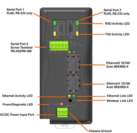
Figure 2-1. XPress DR+ (Front)
Note: For a diagram and description of XPress DR+W, see Front Panel Description on page 31.
The XPress DR+ supports RS-232 through RJ45 connectors. It also supports RS-422/485 by means of screw terminals (Serial Port 2 only). It has two Ethernet Ports 10/100Base-T and –TX with Auto MDI/MDI-X by means of RJ45 connectors. You can use either Ethernet port for daisy-chained configuration.
XPress DR+ User Guide |
13 |
Chapter 2: Introduction
Industrial Automation Protocols
The XPress DR+, adapted to multiple factory environments, can unite any mixture of equipment from industrial automation vendors into a single reliable pipeline. This new and open infrastructure opens the way for data to flow in real time from all your plant devices up to your IT layer.
The XPress DR+ is delivered with IAP Standard Tunneling protocol and can be loaded with industrial communication protocols. The suite of protocols includes DF1 Multi-Master (Rockwell Automation) and Modbus Bridge, which supports MODBUS/TCP, MODBUS/ASCII, and MODBUS/RTU (Schneider Electric). Where the IAP Standard Tunneling protocol is limited to standard ASCII device-to-device connections, the industrial protocols offer connections to other devices that require special formatting or features simultaneously.
For information about using any of the industrial communication protocols, see the specific protocol guides on the software CD or the Lantronix web site. Protocol firmware files are also on the CD.
Note: Please check the Lantronix web site for newer versions that may become available.
You can set up the unit using serial port 1 or remotely over Ethernet using Telnet or, when using the Standard Tunneling firmware, a web browser. The CD that comes with your device server includes DeviceInstaller, a Windows-based configuration software that simplifies the process of installing protocols and configuring them for use with attached devices. The XPress DR+ uses Flash memory for maintenance-free, non-volatile storage that allows fast system upgrades.
Network Protocols (Serial Tunneling)
The XPress DR+ uses TCP/IP protocols for network communication. The supported standards are ARP, UDP, TCP, ICMP, Telnet, TFTP, DHCP, AutoIP, MODBUS/TCP, and SNMP. For transparent connections, TCP/IP (binary stream) or Telnet protocols are used. You can perform firmware upgrades with the TFTP protocol.
The IP (Internet Protocol) protocol defines addressing, routing, and data-block handling over the network. The TCP (transmission control protocol) assures that no data is lost or duplicated, and that everything sent into the connection on one side arrives at the target exactly as it was sent.
For typical datagram applications, where devices interact with others without maintaining a point-to-point connection, UDP datagram is supported in the Standard Tunnel Protocol.
XPress DR+ comes loaded with Standard Tunnel Protocol. Standard Tunneling is a serial communications protocol used by most Lantronix device servers. You can configure it to Ethernet-enable most serial devices such as barcode scanners, weigh scales, operator panels, data access devices, alphanumeric displays, and thousands of intelligent serial devices.
XPress DR+ User Guide |
14 |
Chapter 2: Introduction
Loading industrial protocols such as Modbus Bridge to an XPress DR+ changes the configuration dialogs. See the user guides on individual protocols for protocol-specific settings and configuration dialogs. Protocol manuals are on the software CD.
Note: This User Guide describes the setup and configuration dialogs for the Standard Tunnel Protocol.
XPress DR+ Application Examples
Note: For XPress DR+W application examples, see Chapter 4: XPress DR+W.
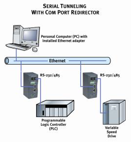
Using a method called serial tunneling, the XPress DR+ encapsulates serial data into packets and transports them over Ethernet. Using two XPress DR+ units, connected by a network, you can extend virtual serial connections across a facility or around the world.
Figure 2-2. Example of Serial Tunneling
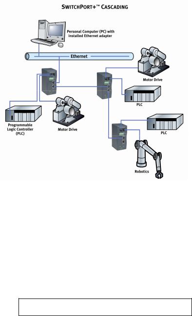
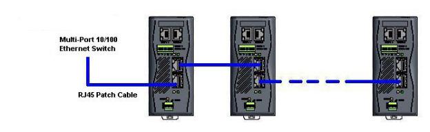
The internal two-port Ethernet switch allows the XPress DR+ to cascade connections from a single network drop to another Ethernet device or from one XPress DR+ to another and another, and so on.
XPress DR+ User Guide |
15 |
Chapter 2: Introduction
Figure 2-3. Example of Cascading Multiple XPress DR+ Units
Note: For examples of wireless applications, see Chapter 4: XPress DR+W.
Addresses and Port Numbers
Hardware Address
The hardware address is also referred to as the Ethernet address or MAC address. The first three bytes of the Ethernet address are fixed and read 00-20-4A, identifying the unit as a Lantronix product. The fourth, fifth, and sixth bytes are unique numbers assigned to each unit.
Figure 2-4. Sample Hardware Address
00-20-4A-14-01-18 or 00:20:4A:14:01:18
IP Address
Every device connected to an IP network must have a unique IP address. This address references the specific unit.
Port Numbers
Every TCP connection and every UDP datagram is defined by a destination IP address and a port number. For example, a Telnet application commonly uses port number 23. A port number is similar to an extension on a phone system.
XPress DR+ User Guide |
16 |
Chapter 2: Introduction
You can associate the unit's serial channel (port) with a specific TCP/UDP port number. Port number 9999 is reserved for access to the unit's Setup (configuration) Mode.
Configuration Methods
After installation, the XPress DR+ requires configuration for the unit to operate correctly on a network. There are three basic methods for logging into the XPress DR+ and editing the configurable settings.
DeviceInstaller: Configures the IP address and other network settings on the XPress DR+ using a Graphical User Interface (GUI) on a PC attached to a network.
(See Chapter 5: Using DeviceInstaller.)
Web Manager: Through a web interface, configures the XPress DR+ settings using the Lantronix Web Manager. (See Chapter 6: Configuration Using Web Manager.)
Serial and Telnet Ports: There are two approaches to accessing Setup Mode: making a Telnet connection to the network port (9999) or connecting a terminal (or a PC running a terminal emulation program) to the unit’s serial port. To use DeviceInstaller for communication to an XPress DR+W over a wireless network, the WLAN network settings must be configured first.
XPress DR+ User Guide |
17 |
Chapter 3: Installation and Hardware
What's in the Box?
Verify and inspect the contents of the package using the enclosed packing slip or the list below. If any item is missing or damaged, contact your place of purchase immediately.
XPress DR+ or XPress DR+W
Resource CD
Quick Start Guide
P/N: 500-103 RJ45-DB9F serial cable.
P/N 930-029 antenna (XPress DR+W only)
Accessory DIN-rail wall mount bracket
3 terminal screw connector for power input
5 terminal screw connector for serial port
What Must the User Provide?
9-30 VDC or 9-24 VAC power source
CAT 5 Ethernet cable (for wired XPress DR+ and the wireless version operating in wired mode)
Physically Connecting the XPress DR+
Note: for information on physically connecting the XPress DR+W in wireless mode, see Chapter 4: XPress DR+W.
Note: To comply with the FM approval of the XPress DR+, the unit must be installed in a tool-secured enclosure and wiring must be installed in accordance with Division 2 wiring practices as specified by the NEC.
This section describes the procedures for getting your unit up and running. For a short version, see the Quick Start Guide. Detailed descriptions of the hardware components of the XPress DR+ follow this simple installation procedure.
The following diagram shows the basic connectivity of an XPress DR+ to the network and a serial device. The Lantronix-supplied P/N: 500-103 serial cable can be used on the RJ45 RS232 serial ports to connect the XPress DR+ to a PC or to a serial device that has a DB9M RS232 DTE interface. If the device being connected uses a different serial interface, please refer to page 22 for the serial interface pinout or to Appendix B: Lantronix Cables and Adapters for a list of serial cables or adapters.
XPress DR+ User Guide |
18 |
Chapter 3: Installation and Hardware
Figure 3-1. Typical Configuration
1.Connect a serial device to your XPress DR+. (See Serial Interface on page 20 for cable and connector specifications.)
2.Connect an Ethernet cable to the Ethernet port. (See Ethernet Interface on page 23.)
3.Supply power to your XPress DR+ using a 9-30 VDC or 9-24 VAC (2.3W maximum) source. (See Power Requirements on page 24.)
4.Supply power to the serial device.
Note: Connecting a device to an active Ethernet network can disrupt communications on the network. Make sure the device is configured for your application before connecting it to an active network
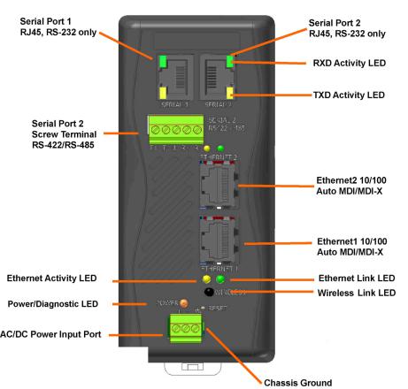
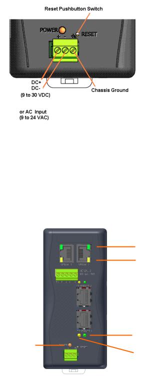
XPress DR+ Front Panel
The following figure illustrates the screw block connector pinouts and other components of the XPress DR+.
Note: For a description of the XPress DR+W front panel, see Chapter 4: XPress DR+W.
XPress DR+ User Guide |
19 |
Chapter 3: Installation and Hardware
Figure 3-2. Front of XPress DR+
Serial Interface
The XPress DR+ supports RS-232 via RJ45 connectors. It also supports RS-422/485 via screw terminals (Serial Port 2 only).
Note: Serial Port 2 supports RS232, RS422, and RS485, but only one mode at a time. This means you can use either the RJ45 connector or the terminal block, not both.
The RJ45 serial connectors only support RS232, up to 230400 bits per second.
XPress DR+ User Guide |
20 |
|
|
|
|
Chapter 3: Installation and Hardware |
Table 3-1. RJ45 Serial Connector Pinouts |
Figure 3-3. RJ45 Connector – Front View |
|||
|
|
|
|
|
Pin |
Direction |
Name |
Function |
|
1 |
Output from DR+ |
RTS |
Ready To Send |
|
2 |
Output from DR+ |
DTR |
Data Terminal Ready |
|
3 |
Output from DR+ |
TXD |
Transmitted Data |
|
4 |
Ground |
GND |
Signal Ground |
|
5 |
Ground |
GND |
Signal Ground |
|
6 |
Input to DR+ |
RXD |
Received Data |
|
7 |
Input to DR+ |
DSR |
Data Carrier Detected |
|
8 |
Input to DR+ |
CTS |
Clear To Send |
|
Screw Terminal Serial Connectors
Table 3-2. Serial Screw Terminal Pinout for RS422 (4-Wire)
Pin |
Direction |
Name |
Function |
1 |
Output |
TX+ |
Transmit Data + |
2 |
Output |
TX- |
Transmit Data - |
3 |
Ground |
GND |
Signal Ground |
4 |
Input |
RX+ |
Received Data + |
5 |
Input |
RX- |
Received Data - |
Table 3-3. Serial Screw Terminal Pinout for RS485 (2-Wire)
Pin |
Direction |
Name |
Function |
1 |
Bi-directional |
TX+/RX+ |
Transmit Data + and Received Data + |
2 |
Bi-directional |
TX-/RX- |
Transmit Data – and Received Data - |
3 |
Ground |
GND |
Signal Ground |
4 |
Not Applicable |
Not Applicable |
Not Used |
5 |
Not Applicable |
Not Applicable |
Not Used |
Figure 3-4. Screw Terminal Ports
XPress DR+ User Guide |
21 |
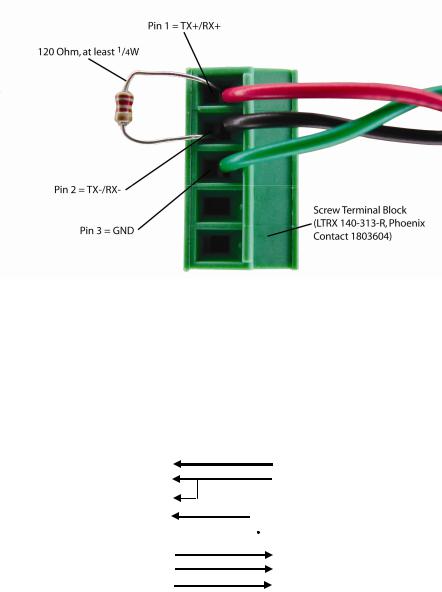
Chapter 3: Installation and Hardware
Note: Termination resistors (R = 120 Ohm) are used to match impedance of a node to the impedance of the transmission (TX) line. Termination resistors should be placed only at the extreme ends of the data line, and no more than two terminations should be placed in any single segment of an RS-485 network. The termination resistors may not be needed for your application.
Figure 3-5. Termination Resistor for 2-Wire Connection
9-Pin RS-232 to Serial RJ45 Cable (P/N 500-103)
The included Lantronix (P/N 500-103) RJ45-DB9F serial cable assumes you are connecting a typical PC Com port to the XPress DR+ serial port. This cable is pinned to provide full serial line control to an RS232 DTE device. Lantronix offers a comprehensive list of cables and adapters to simplify device connectivity to the XPress DR+. See Appendix B: Lantronix Cables and Adapters for a full listing.
Figure 3-6. Lantronix P/N 500-103 RJ45-DB9F Serial Cable Pinout
8 |
|
CTS (In) |
|
|
|
1 |
RTS (Out) |
|
1 |
|
DCD (In) |
|
|
|
2 |
DTR (Out) |
|
6 |
|
DSR (In) |
|
|
|
3 |
TXD |
|
|
|
|
|
|||||
2 |
|
RXD (In) |
|
|
|
4 |
Signal Ground |
|
|
|
|
|
|||||
5 |
|
Signal Ground |
|
|
|
|
5 |
Signal Ground |
|
|
|
|
|
||||
3 |
|
TXD (Out) |
|
|
|
6 |
RXD |
|
4 |
|
DTR (Out) |
|
|
|
7 |
DSR (In ) |
|
7 |
|
RTS (Out) |
|
|
|
8 |
CTS (In) |
|
DTE, 9-Pin |
|
|
|
XPress DR+ |
||||
|
Female |
|
|
|
Serial RJ45 |
|||
XPress DR+ User Guide |
22 |
Chapter 3: Installation and Hardware
Ethernet Interface
The XPress DR+ includes a two-port unmanaged Ethernet switch with a future option to migrate to a managed solution.
The internal IEEE 802.3-compliant Ethernet switch is non-blocking, using a 1K MAC address lookup table with store-and-forward architecture. The XPress DR+ supports auto-negotiation for 10Base-T or 100Base-TX in full and half-duplex modes, as well as automatic MDI/MDIX crossover, allowing use of both straight-through and crossed Ethernet cables. The unit also supports IEEE 802.1d spanning tree, which protects against the possibility of a network loop.
Table 3-4. Ethernet Interface Signals
Pin |
Direction |
Name |
Function |
TX+ |
Out |
1 |
Transmit Data + |
TX- |
Out |
2 |
Transmit Data - |
RX+ |
In |
3 |
Differential Ethernet Receive Data + |
RX- |
In |
6 |
Differential Ethernet Receive Data - |
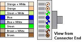
The next drawing shows a typical RJ45 connector. The color is not standard but very typical of an Ethernet patch cable. Pin 1 is located at the top of the connector (orange + white). The view is from the end of the connector.
Table 3-5.Typical RJ45 Connector
XPress DR+ User Guide |
23 |
Chapter 3: Installation and Hardware
Multi-Drop Ethernet Connections
Although there are two Ethernet ports, the XPress DR+ only has one MAC address and IP address. Either port can be used as the primary connection with the other used
to inter-connect other Ethernet devices or cascade from one XPress DR+ to another.
Figure 3-7. Multi-Drop Ethernet Connections
Power Requirements
As with most industrial automation devices, the XPress DR+ does not ship with a power supply. Its flexible power input circuit allows the product to be powered by any 9-30 VDC or 9-24 VAC power supply that can provide the 2.3-Watt maximum required by the XPress DR+.
In addition to the wide power input range, the XPress DR+ provides:
2K VAC and 2.8K VDC galvanic isolation between the power input and the Ethernet ports
2K VAC and 2.8K VDC galvanic isolation between the power input and the serial ports
Reset Switch
The XPress DR+ includes a hardware reset switch located in the small hole above the power connector. Pressing the reset switch causes a hardware reboot of the
XPress DR+. The hardware reset does not reset or change the configuration of the XPress DR+.
XPress DR+ User Guide |
24 |
Chapter 3: Installation and Hardware
Figure 3-8. Reset Switch
Caution: Even though a chassis ground is not required for operation, it is mandatory for protection against transient voltages and ESD. A chassis ground must be connected to earth.
LEDs
Note: For a description of the XPress DR+W's LEDs, see page 32.
Figure 3-9. LEDs on the XPress DR
RXD Activity LED
TXD Activity LED
Ethernet Link LED
Power/Diagnostic LED
Ethernet Activity LED
XPress DR+ User Guide |
25 |

Chapter 3: Installation and Hardware
Table 3-6. XPress DR+ LED Functions
LED |
|
Status |
|
Meaning |
Serial port - TXD LED (Yellow) |
|
Off |
|
No data being transmitted from XPress DR+ |
|
|
|
|
|
|
|
Blinking |
|
Data being transmitted from XPress DR+ |
|
|
|
||
|
|
|
|
|
Serial port - RXD LED (Green) |
|
Off |
|
No data being received by XPress DR+ |
|
|
|
|
|
|
|
Blinking |
|
Data being received by XPress DR+ |
|
|
|
||
|
|
|
|
|
Ethernet port - 10/100 Link (Green) |
|
Off |
|
No Ethernet link established |
|
|
|
|
|
|
|
Steady On |
|
Ethernet link established |
|
|
|
||
|
|
|
|
|
Ethernet port – Activity (Yellow) |
|
Off |
|
No data activity |
|
|
|
|
|
|
|
Blinking |
|
Data activity |
|
|
|
||
|
|
|
|
|
Power/Diagnostic LED (Orange) |
|
Steady On |
|
Power OK |
|
|
|
|
|
|
|
Blinking 2x |
|
No DHCP response |
|
|
|
||
|
|
|
|
|
|
|
Blinking |
|
Setup Menu active |
|
|
|
|
|
Dimensions
The following drawing shows the dimensions of the XPress DR+
Figure 3-10. Dimensions
XPress DR+ User Guide |
26 |
Chapter 3: Installation and Hardware
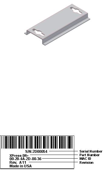
Wall Mount Bracket
Included with the XPress DR+ is an accessory DIN-rail wall mount bracket that makes it very easy to mount the unit in locations where a DIN-rail is not available.
Figure 3-11. Wall Mount Bracket
Product Information Label
The product information label on the underside of the unit contains important information about your specific unit:
Bar code
Serial number
Product ID (name)
Product description
Hardware address (also referred to as Ethernet or MAC address) Your unit will have one similar to the one below.
Figure 3-12. Product Label
Note: Before mounting the device on a DIN-rail, copy the information from the label.
XPress DR+ User Guide |
27 |
Chapter 4: XPress DR+W
The wireless version of the XPress DR+ (XPress DR+W) provides serial-to-wireless network connectivity as an alternative to wired Ethernet connectivity. The wireless unit uses IP protocol (TCP for connection-oriented stream applications and UDP for datagram applications), enabling virtually any serial device or equipment to be remotely accessed, controlled, monitored, or shared on an 802.11b/g wireless network. The XPress DR+W provides a fully integrated solution that combines an operating system, embedded Web server, full TCP/IP protocol stack with an 802.11b/g transceiver supporting WEP and WPA security.
Application Examples
The XPress DR+W has an 802.11b/g transceiver in addition to its serial and Ethernet ports. Each serial port is connected to the serial communication port of a device. The wireless transceiver connects to another wireless device or to an Access Point (AP). This section includes typical scenarios for using the XPress DR+W.
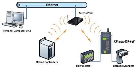
Serial Tunneling – Network
Figure 4-1. Serial Tunneling Infrastructure Network Example
MARCOM IS FIXING
A PC connected to an AP via an Ethernet connection and a PC with a wireless connection to the AP LAN access the XPress DR+ W as though they are directly
XPress DR+ User Guide |
28 |

Chapter 4: XPress DR+W
connected to it. The combination of the XPress DR+W, a PC, and Lantronix’s Com Port Redirector software allows the PC to communicate directly to the wireless unit’s serial devices, providing wireless serial tunneling. Com Port Redirector is available on the product CD and the Lantronix web site (www.lantronix.com).
Ad Hoc Network
Figure 4-2. Ad Hoc Network Example
In the example above, the AP is not present. The PC makes a direct wireless connection with the XPress DR+W to manage serial devices. Without an AP, it is a peer-to-peer relationship.
Serial Tunneling – Infrastructure
Figure 4-3. Serial Tunneling Infrastructure Example
MARCOM IS FIXING
XPress DR+ User Guide |
29 |
Chapter 4: XPress DR+W
In the example above, the XPress DR+W communicates with another device server via the AP. The UDS device server, in this example, is connected via an Ethernet connection to the AP. In this way, the XPress DR+W and the device server communicate directly and can transfer information between their serial devices.
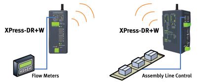
Ad Hoc XPress DR+W Connection
Figure 4-4. Direct XPress DR+W - toXPress DR+W Connection
In the example above, two XPress DR+W s have established an Ad Hoc peer-to-peer relationship. They communicate directly to each other’s serial devices without a PC or an AP.
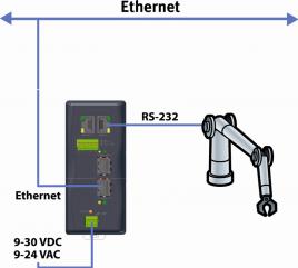
Physically Connecting the XPress DR+W
Note: See page 33 for instructions on setting up the unit to configure it the first time.
To install the XPress DR+W:
1.Screw the antenna into the receptacle at the top of the XPress DR+.
2.Connect a serial device to your XPress DR+W. (See Serial Interface on page 20 for cable and connector specifications.)
3.Supply power to your XPress DR+ using a 9-30 VDC or 9-24 VAC (2.3W maximum) source. (See Power Requirements on page 24.)
4.Supply power to the serial device.
XPress DR+ User Guide |
30 |
Loading...