


 Loading...
MPS/LPS Installation Guide
For the MPS100, LPS1-T and LPS1-2
Micro Print Servers


The information in this guide may change without notice. The manufacturer assumes no responsibility for any errors which may appear in this guide.
AppleTalk, Chooser, and Macintosh are trademarks of Apple Computer Corporation. LaserJet and Bitronics are trademarks of Hewlett Packard. Centronics is a registered trademark of Centronics Data Computer Corporation. PostScript is a trademark of Adobe Systems, Inc. DEC and LAT are trademarks of Digital Equipment Corporation. Ethernet is a trademark of XEROX Corporation. NetWare is a trademark of Novell Corporation. UNIX is a registered trademark of The Open Group. Windows for Workgroups, Windows 95, Windows 98, Windows 2000, and Windows NT are trademarks of Microsoft Corporation.
Copyright 2000, Lantronix. All rights reserved. No part of the contents of this book may be transmitted or reproduced in any form or by any means without the written permission of Lantronix. Printed in the United States of America.
The revision date for this manual is 23 October, 2000.
Part Number: 900-191
Rev. B
WARNING
This product has been designed to comply with the limits for a Class A digital device pursuant to Part 15 of FCC Rules. These limits are designed to provide reasonable protection against such interference when operating in a commercial environment. This equipment generates, uses, and can radiate radio frequency energy, and if not installed and used in accordance with this guide, may cause harmful interference to radio communications.
Operation of this equipment in a residential area is likely to cause interference in which case the user, at his or her own expense, will be required to take whatever measures may be required to correct the interference.
Changes or modifications to this device not explicitly approved by Lantronix will void the user’s authority to operate this device.
Cet appareil doit se soumettre avec la section 15 des statuts et règlements de FCC. Le fonctionnement est subjecté aux conditions suivantes:
(1)Cet appareil ne doit pas causer une interférence malfaisante.
(2)Cet appareil doît accepter n'importé quelle interférence reìue qui peut causer une opération indésirable.


Contents
1: Introduction.......................................................................... |
1-1 |
|
1.1 |
How to Use This Manual................................................................. |
1-1 |
2: Installation............................................................................ |
2-1 |
|
2.1 |
MPS/LPS Product Description ........................................................ |
2-1 |
2.2 |
Installing the MPS ........................................................................... |
2-2 |
3: Getting Started..................................................................... |
3-1 |
|
3.1 |
Configuration Methods.................................................................... |
3-1 |
|
3.1.1 EZWebCon ...................................................................... |
3-1 |
|
3.1.2 Incoming Logins.............................................................. |
3-1 |
3.2 |
Services............................................................................................ |
3-2 |
4: TCP/IP Configuration........................................................... |
4-1 |
|
4.1 |
Setting the IP Address ..................................................................... |
4-1 |
|
4.1.1 Using EZWebCon ........................................................... |
4-1 |
|
4.1.2 Using a Directed Ping Packet .......................................... |
4-1 |
|
4.1.3 Using a BOOTP, DHCP, or RARP Reply....................... |
4-3 |
|
4.1.4 Using the Command Line Interface ................................ |
4-3 |
4.2 |
LPR Printing .................................................................................... |
4-3 |
|
4.2.1 LPR on Windows NT 3.5.1 (and later)............................ |
4-4 |
|
4.2.2 LPR on Windows 95/98 .................................................. |
4-7 |
|
4.2.3 LPR on UNIX Hosts........................................................ |
4-7 |
|
4.2.4 LPR on AIX Hosts........................................................... |
4-8 |
|
4.2.5 LPR on HP Hosts............................................................. |
4-9 |
|
4.2.6 LPR on SCO UNIX Hosts ............................................. |
4-10 |
|
4.2.7 RTEL Functionality....................................................... |
4-11 |
4.3 |
Unix Host Troubleshooting ........................................................... |
4-12 |
5: NetWare Configuration........................................................ |
5-1 |
|
5.1 |
NDPS Printing ................................................................................. |
5-1 |
5.2 |
NDS Print Queues ........................................................................... |
5-1 |
|
5.2.1 Obtain an NDS License ................................................... |
5-1 |
|
5.2.2 Configure your MPS........................................................ |
5-2 |
5.3 |
NetWare Administrator Quick Setup Print Queues......................... |
5-2 |
5.4 PCONSOLE Print Queues............................................................... |
5-3 |
|
i

Contents
5.5 NetWare Host Troubleshooting ....................................................... |
5-4 |
6: LAT Configuration ............................................................... |
6-1 |
||
6.1 |
Printing Directly to a Port................................................................ |
6-1 |
|
6.2 |
LAT Host Troubleshooting.............................................................. |
6-2 |
|
7: AppleTalk Configuration ..................................................... |
7-1 |
||
7.1 |
Bitronics........................................................................................... |
7-1 |
|
7.2 |
Macintosh Services .......................................................................... |
7-1 |
|
7.3 |
AppleTalk Zones ............................................................................. |
7-1 |
|
7.4 |
AppleTalk Host Troubleshooting .................................................... |
7-2 |
|
8: DLC Configuration for LAN Manager................................. |
8-1 |
||
8.1 |
DLC Configuration .......................................................................... |
8-1 |
|
|
|
8.1.1 MPS Configuration.......................................................... |
8-1 |
|
|
8.1.2 Host Configuration .......................................................... |
8-1 |
A: Contact Information ........................................................... |
A-1 |
||
A.1 Problem Report Procedure............................................................. |
A-1 |
||
A.2 Full Contact Information ............................................................... |
A-1 |
||
B: Troubleshooting ................................................................. |
B-1 |
||
B.1 |
Power-up Troubleshooting.............................................................. |
B-1 |
|
B.2 |
DHCP Troubleshooting................................................................... |
B-3 |
|
B.3 |
BOOTP Troubleshooting ................................................................ |
B-4 |
|
B.4 |
RARP Troubleshooting................................................................... |
B-4 |
|
B.5 |
Printing Problems............................................................................ |
B-5 |
|
B.6 |
Entering Commands at the Boot Prompt ........................................ |
B-6 |
|
C: Pinouts ................................................................................ |
C-1 |
||
C.1 |
Ethernet Connector ......................................................................... |
C-1 |
|
C.2 |
Parallel Connectors ......................................................................... |
C-1 |
|
D: Updating Software ............................................................. |
D-1 |
||
D.1 Obtaining Software ........................................................................ |
D-1 |
||
D.2 Reloading Software........................................................................ |
D-2 |
||
D.3 Troubleshooting Flash ROM Updates ........................................... |
D-4 |
||
ii

|
|
Contents |
E: Specifications ...................................................................... |
E-1 |
|
E.1 |
Power Information .......................................................................... |
E-1 |
E.2 |
Environmental Limitations.............................................................. |
E-1 |
F: Frequently-used Commands .............................................. |
F-1 |
|
F.1 |
Conventions..................................................................................... |
F-1 |
F.2 Server Commands ........................................................................... |
F-2 |
|
F.3 Port Commands ............................................................................... |
F-5 |
|
F.4 |
Protocol Commands ........................................................................ |
F-7 |
Warranty Statement
Declaration of Conformity
Index
iii


1: Introduction
The Lantronix Micro Print Servers (MPS100, LPS1-T and LPS1-2 models) are multiprotocol print servers that provide shared network access to printers for a variety of network protocols and operating systems. The MPS supports the TCP/IP, IPX (NetWare), Local Area Transport (LAT), AppleTalk, and LAN Manager protocols. The LPS supports TCP/IP, NetWare, and LAT. Both types of servers can queue multiple pending jobs and service those jobs in the order in which they are received from hosts.
The MPS100 can auto-negotiate between 10BASE-T and 100BASE-T media connected to its RJ45 port. The features, installation process, and configuration procedures are the same. The LPS provides a twisted pair (10BASE-T) or BNC (10BASE-2) connector for network connections.
Note: In this manual, all MPS and LPS servers will be referred to as “ the MPS” unless a distinction needs to be mad e between models.
1.1 How to Use This Manual
This guide is structured as follows:
Chapter 2, Installation explains how to physically install the MPS.
Chapter 3, Getting Started explains the minimum configuration needed.
Chapters 4 through 8 cover protocol-specific setup needed to install print queues and otherwise use the MPS.
Chapter 4, TCP/IP Configuration
Chapter 5, NetWare Configuration
Chapter 6, LAT Configuration
Chapter 7, AppleTalk Configuration
Chapter 8, DLC Configuration for LAN Manager
Appendices A through F provide supplementary information.
Appendix A, Contact Information
Appendix B, Troubleshooting
Appendix C, Pinouts
Appendix D, Updating Software
Appendix E, Specifications
1-1

How to Use This Manual |
Introduction |
Appendix F, Frequently-used Commands
Read chapters 2 through 4 in order, then proceed to the protocol-specific chapter that relates to your network. Refer to Appendix F as needed. The Print Server Reference Manual, located on the CD-ROM and web site, provides additional information about configuring and using your MPS.
1-2
2: Installation
This chapter describes the various MPS models and shows how to install them into a basic network situation.
2.1 MPS/LPS Product Description
The front panel of the MPS100 has a Test button, 3 LEDs, a power connector, and an RJ45 connector for 100BASE-T. The rear panel has a Centronics connector. The front
“back” |
Centronics Connector |
LINK AC 100T |
TEST |
5VDC |
“front” |
panel of the LPS has a Test button, 2 LED’s, a power connector, and a 10BASE-T network connector for the LPS1-T or a 10BASE-2 BNC connector for the LPS1-2. The rear panel also has a Centronics connector.
The LINK LED is solid green when there is a valid Ethernet network connection. The ACT (Activity) LED flashes green or red when the MPS is in use. The 100 (100 MBit) LED (MPS100 only) is solid green when a 100BASE-T network is connected.
The Test button serves two functions. When pressed briefly, it prints a test page. When pressed for five seconds while plugging in the power cable, it returns the MPS to its factory default configuration.
2-1
Installing the MPS |
Installation |
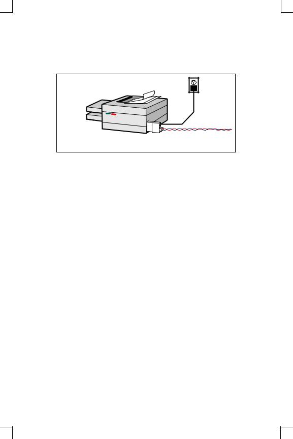
2.2 Installing the MPS
The following diagram shows a properly-installed MPS:
PARALLEL PRINTER
3
Network Connection
1 2
To install the MPS, complete the following steps in order. Refer to the numbers in the figure for help.
1Connect the MPS Centronics connector directly to your printer’s connector.
2Connect an Ethernet cable to your MPS’s RJ45 or BNC connector.
3Attach one end of the power cable to the MPS; plug the other end into an electrical outlet. Power will come on automatically.
4Allow 45 seconds for the MPS to fully boot.
It will run through a set of power-up diagnostics for approximately 12 seconds. The 4 LEDs will show varying patterns corresponding to the test being run.
It will try to obtain configuration information via DHCP, BOOTP, and RARP. This step could last approximately 15 seconds if no hosts answer the requests. The OK LED will blink approximately 3 times per second, and the NETWORK LED will blink occasionally as network requests are transmitted.
It will determine if the code in its Flash is valid. If so, it will load the code and begin normal execution. If not, the MPS will have to download software. See Appendix D for more information.
2-2

Installation |
Installing the MPS |
5Allow 45 seconds for the unit to fully boot. The LINK LED will be lit if there is a valid network connection. The ACT LED gives information about what the MPS is doing; for example, when code is being downloaded as the unit boots, the LED will blink green quickly. If you have connected a 100BASE-T cable (MPS100 only), The Link and 100MBit LEDs should both be solid green. If not, check your network connection.
6Print a Test page by pressing the Test/Reset button.
Note: If the Power LED does not light or the Test page does not print, refer to Appendix B.
2-3


3: Getting Started
It is important to consider the following points before logging into and configuring the MPS:
You must configure the MPS IP address before any TCP/IP functionality is available. (See Setting the IP Address on page 4-1) You cannot use the ThinWeb Manager until you have configured an IP address.
Changing any server, service, or port setting requires privileged user status. The default privileged password is system.
The login password is required for remote console logins. The default login password is access.
Note: If you would like to change either the privileged or login password, either use EZWebCon or refer to the Print Server Reference Manual located on the CD-ROM.
3.1 Configuration Methods
3.1.1 EZWebCon
The EZWebCon configuration software is the recommended way to configure the MPS. EZWebCon’s graphical user interface guides first time users through the initial configuration process and allows experienced users to update any configurable parameters.
EZWebCon requires a Java Virtual Machine (JVM) on the client. Lantronix provides JVM installers for Solaris and 32-bit Windows users, as well as source code and instructions for compiling it for other systems.
The EZWebCon software is located on the distribution CD-ROM. All instructions for installing EZWebCon are provided in the README file. For assistance once EZWebCon is running, refer to the EZWebCon on-line help.
Note: EZWebCon is also available from the Lantronix website and FTP server. See Appendix D for more information.
3.1.2 Incoming Logins
You can log in via EZWebCon to configure the MPS. you can also use incoming LAT and TCP/IP logins.
3-1

Services |
Getting Started |
Incoming Telnet is only possible if your MPS has an IP address configured. Incoming Telnet is enabled by default to allow TCP/IP connections. To change this setting, use the Define Server Incoming command described in the Command Reference chapter of the
Print Server Reference Manual located on the CD-ROM.
Incoming logins do not prompt for a login password, so you may wish to disable them for security reasons. If it is undesirable to disable incoming logins, the MPS can be configured to prompt for a password with the Define Server Incoming Password Enabled command.
3.2 Services
With few exceptions, you must create a service before you can configure print queues on the MPS. A service is a resource accessible to network hosts. A Lantronix service is also known as a remote printer name or remote queue name on many operating systems.
The following default services are available once the MPS100, LPS1-T, or LPS1-2 has booted:
Table 3-1: Default Services
MPS100 |
LPS1-T & LPS1-2 |
Function |
|
|
|
|
|
|
MPS_xxxxxx_TEXT |
LPS_xxxxxx_TEXT |
Used for text print |
|
|
jobs |
MPS_xxxxxx_PCL |
LPS_xxxxxx_PCL |
Used for binary |
|
|
print jobs, such as |
|
|
plotter or PCL |
|
|
files |
MPS_xxxxxx_PS |
LPS_xxxxxx_PS |
Used for Post- |
|
|
Script print jobs |
|
|
|
The default service names are based on the server name; therefore the server name must be no more than 13 characters. If you change the server name, the service names will change as well. For example, changing the server name from MPS_xxxxxx to BIOLAB will change the service names to BIOLAB_TEXTS1 and so on.
The default serial port services have the TCP/IP, NetWare, LAN Manager, and AppleTalk protocols enabled. Parallel port services have TCP/IP, NetWare, and LAN Manager enabled. LAT is disabled by default on all services provided by the MPS because many network managers object to the frequent LAT service announcements. AppleTalk is disabled on parallel port services because AppleTalk requires Bitronics mode, which is disabled by default.
If you need to modify a default service, see the Server Configuration chapter of the Print Server Reference Manual located on the CD-ROM.
3-2

4: TCP/IP Configuration
The EZWebCon configuration software is the easiest way to configure the MPS. The following sections cover IP address configuration and print configuration methods for TCP/ IP hosts.
4.1 Setting the IP Address
The MPS IP address must be configured before any TCP/IP functionality is available. Use one of the following methods to set the IP address: EZWebCon; a directed Ping packet; a BOOTP, DHCP, or RARP reply; or commands entered via the command line interface.
4.1.1 Using EZWebCon
Use the following steps to assign an IP address using the EZWebCon Expert Shell.
1From the Action menu, select Assign IP Address.
2Enter or change the IP-related settings:
A For Ethernet Address, enter the number that appears on the bottom label of your MPS.
B For IP Address, enter the desired IP address to use for this MPS.
C For Subnet Mask, change the values provided only if you wish to use a mask other than the default. The default value should be correct in most cases.
D For Loadhost, enter the IP address of the loadhost where you intend to store your operating code and SDK files (if used).
3Click OK.
4Reboot the MPS. EZWebCon will let you know whether the configuration was successful.
Note: If you have an older version of EZWebCon, refer to the Readme that was included with it.
4.1.2 Using a Directed Ping Packet
The ARP/ping method is available under UNIX and Windows-based systems. If the MPS has no IP address, it will set its address from the first directed IP packet it receives.
4-1

Setting the IP Address |
TCP/IP Configuration |
On a UNIX host, create an entry in the host’s ARP table and substitute the intended IP address and the hardware address of the MPS, then ping the MPS. This process typically requires superuser privileges.
Figure 4-1: ARP and Ping on UNIX
# arp -s 192.0.1.228 00-80-a3-xx-xx-xx % ping 192.0.1.228
In order for the ARP command to work on Windows, the ARP table on the PC must have at least one IP address defined other than its own. If the ARP table is empty, the command will return an error message. Type ARP -A at the DOS command prompt to verify that there is at least one entry in the ARP table.
Figure 4-2: ARP and Ping on Windows
C:\ ARP -S 192.0.1.228 00-80-A3-XX-XX-XX
C:\ PING 192.0.1.228
Note: There should be replies from the IP address if the ARP command worked.
When the MPS receives the ping packet, it will notice that its IP address is not set and will send out broadcasts to see if another node is using the specified address. If no duplicate is found, the MPS will use the IP address and will respond to the ping packet.
The MPS will not save the learned IP address permanently; this procedure is intended as a temporary measure to enable EZWebCon to communicate with the MPS, or allow an administrator to Telnet into the MPS. Once logged in, the administrator can enter the Change IPaddress command to make the address permanent.
Figure 4-3: Configuring Permanent IP Address
% telnet 192.0.1.228
Trying 192.0.1.228
Lantronix MPSx Version n.n/n (yymmdd)
Type Help at the ‘Local_>’ prompt for assistance.
Enter Username> gopher
Local> SET PRIVILEGED
Password> system (not echoed)
Local>> DEFINE SERVER IPADDRESS 192.0.1.228
Any host wishing to access the MPS will have to be told the MPS’s IP address. This is typically configured in the unix file /etc/hosts or via a nameserver. Refer to the host’s documentation for additional information.
4-2
TCP/IP Configuration |
LPR Printing |
4.1.3 Using a BOOTP, DHCP, or RARP Reply
At boot time a host-based DHCP, BOOTP, or RARP server can respond to an MPS request for an available IP address. For information about configuring the DHCP, BOOTP, or RARP server, see your host documentation.
4.1.4 Using the Command Line Interface
1Connect to the serial port (Port_1) using a console terminal or a terminal emulation program, and press Return. The serial port settings are 9600 baud, 8 bits, 1 stop bit, no parity.
2Become the privileged user.
Figure 4-4: Becoming the Privileged User
Local> SET PRIVILEGED
Password> system (not echoed)
Local>>
3 Enter the new IP address.
Figure 4-5: Configuring the IP Address
Local>> define server ipaddress 192.0.1.201
4.2 LPR Printing
The MPS provides two major methods of printing via TCP/IP: Berkeley remote LPR and RTEL host software.
Two parameters must be configured for LPR printing:
1The IP address or host name of the MPS.
2The remote output queue (the name of the service on the MPS). In addition, there are a few important things to note about LPR printing:
Windows for Workgroups, Windows 95, and Windows 98 do not support LPR directly; however, Lantronix has provided a peer-to-peer printing solution on the distribution CD-ROM.
Because of the way the LPR protocol is typically implemented on the host, the processing options and banner page are sent after the job data itself. The MPS will print a banner page at the end of a job, and cannot support most of the LPR options. If it is necessary to have the banner page at the beginning of the printout, install and use the RTEL software. If banners are not needed, they can be disabled.
4-3
LPR Printing |
TCP/IP Configuration |
The MPS cannot print multiple copies of the print job when using the “-#n” lpr option.
If two print queues on the host refer to two services on the same MPS, they must use separate spooling directories.
No special purpose input or output filters can be used when printing via LPR. If this functionality is necessary, use the named pipe interface program in the RTEL print queue configuration software.
4.2.1 LPR on Windows NT 3.5.1 (and later)
This section assumes that TCP/IP, Simple TCP/IP, and Microsoft TCP/IP printing have been installed on the Windows NT host.
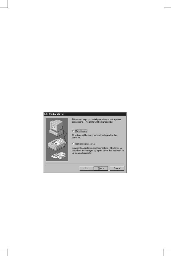
1In the Control Panel, double-click the Printers icon.
2Double-click the Add Printer icon.
3In the window that appears, choose My computer and click Next.
4-4

TCP/IP Configuration |
LPR Printing |
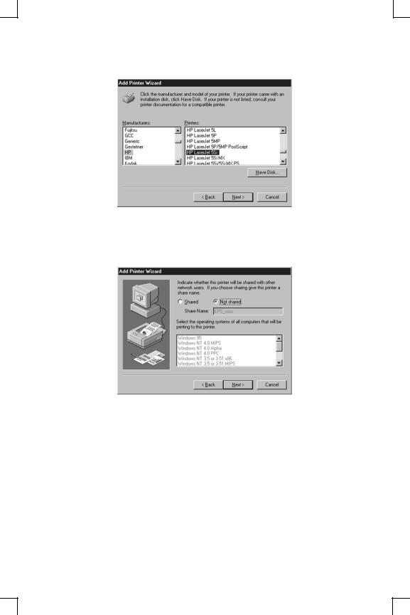
4 Select the Add Port button and click Next.
5 Select LPR Port.
Note: If LPR Port is not an option, open the Network Control Panel and add “Microsoft TCP/IP Printing” to the List of services.
6Enter the name or IP address of your MPS on the first line, and enter the name of your MPS print service on the second line.
4-5
LPR Printing |
TCP/IP Configuration |
7 Select the manufacturer and printer type.
8Enter the queue name.
9If applicable, choose Shared and select the type of operating system that the printer will be working with. (First confirm that the print queue is working.)
4-6
TCP/IP Configuration |
LPR Printing |
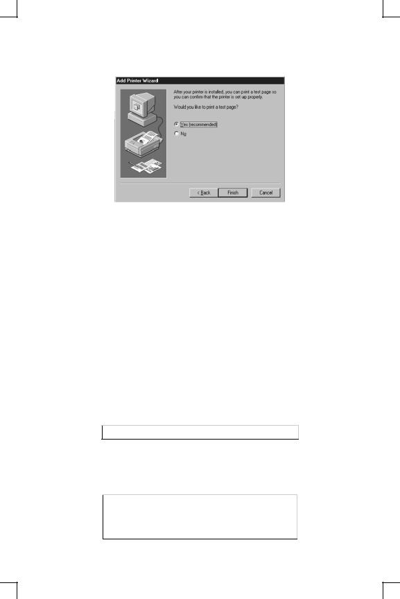
10 Test the printer by choosing Yes and clicking Finish.
4.2.2 LPR on Windows 95/98
To enable LPR printing on Windows 95/98, you must download and install the LPR for Windows 95/98 application from the Lantronix CD included with the product.
1From the Distribution CD, install Lantronix LPR.
2Follow the directions in the readme file to configure LPR on your PC.
4.2.3 LPR on UNIX Hosts
The Berkeley remote printing system is supported on many machines, and is simple to configure. This section describes how to configure LPR print queues on generic UNIX hosts such as SUN hosts. There are slight variations in LPR configuration for AIX, HP, and SCO hosts, as will be explained in the following sections.
1Install a print queue on your host by adding the MPS name and IP address to the
/etc/hosts file:
Figure 4-6: Adding /etc/hosts Entry
xxx.xxx.xxx.xxx MPS_xxxxxx
2Add the host print queue to the /etc/printcap file. The punctuation shown in Figure 4-7 is required, and no extra spaces should be added.
Figure 4-7: Adding /etc/printcap Entry
mps_prt|Printer on LAB MPS:\ :rm=MPS_xxxxxx:\ :rp=MPS_xxxxxx_TEXT:\ :sd=/usr/spool/lpd/mps_prt:
4-7
Loading...