


 Loading...
Table of Contents
Snow Blowers
SB1051, SB1064, SB1574, & SB2584 with S/N 881640-
33234 |
SB10 Series Shown with Optional Hydraulic Chute Rotor and Hydraulic Chute Tilt |
370-027M Operator’s Manual
Read the Operator’s Manual entirely. When you see this symbol, ! the subsequent instructions and warnings are serious - follow
without exception. Your life and the lives of others depend on it!
Cover illustration may show optional equipment not supplied with standard unit.
© Copyright 2014 Pr inted 10/08/14 |
SB10 Series |
SB15 Series |
SB25 Series |

Table of Contents
Important Safety Information . . . . . . . . . . . . . 1
Safety at All Times . . . . . . . . . . . . . . . . . . . . . . . . . 1
Look For The Safety Alert Symbol . . . . . . . . . . . . . 1
Safety Labels . . . . . . . . . . . . . . . . . . . . . . . . . . . . . 4
Introduction . . . . . . . . . . . . . . . . . . . . . . . . . . . |
7 |
Application . . . . . . . . . . . . . . . . . . . . . . . . . . . . . . . . 7
Using This Manual . . . . . . . . . . . . . . . . . . . . . . . . . . 7
Owner Assistance . . . . . . . . . . . . . . . . . . . . . . . . . . 7
Serial Number . . . . . . . . . . . . . . . . . . . . . . . . . . . 7
Section 1: Standard Assembly & Set-up . . . . 8
Tractor Requirements . . . . . . . . . . . . . . . . . . . . . . . 8
Torque Requirements . . . . . . . . . . . . . . . . . . . . . . . 8
Dealer Set-up Instructions . . . . . . . . . . . . . . . . . . . . 8
Loading & Unloading . . . . . . . . . . . . . . . . . . . . . . 8
Chute Assembly . . . . . . . . . . . . . . . . . . . . . . . . . . . 8
Section 2: Optional Assembly & Set-up . . . . . 9
Chute Rotation, Manual . . . . . . . . . . . . . . . . . . . . . . 9
Chute Rotation, Electric Motor . . . . . . . . . . . . . . . . 10
Chute Rotation, Hydraulic Motor . . . . . . . . . . . . . . 11
Chute Tilt, Manual . . . . . . . . . . . . . . . . . . . . . . . . . 12
Chute Tilt, Electric Actuated . . . . . . . . . . . . . . . . . 12
Chute Tilt, Hydraulic Cylinder . . . . . . . . . . . . . . . . 12
Wear Bar, Lower . . . . . . . . . . . . . . . . . . . . . . . . . . 13
Skid Shoes, Outer . . . . . . . . . . . . . . . . . . . . . . . . . 13
Wear Bars, Outer . . . . . . . . . . . . . . . . . . . . . . . . . 13
Skid Shoes, Inner . . . . . . . . . . . . . . . . . . . . . . . . . 13
Section 3: Tractor Hook-up & Unhook . . . . . 14
Snow Blower Hook-up . . . . . . . . . . . . . . . . . . . . . . 14
Leveling The Snow Blower . . . . . . . . . . . . . . . . . . 14
Driveline Installation . . . . . . . . . . . . . . . . . . . . . . . 15
Check Driveline Collapsible Length . . . . . . . . . . 15
Shorten Driveline . . . . . . . . . . . . . . . . . . . . . . . . 15
Check Driveline Maximum Length . . . . . . . . . . . 16
Check Driveline Interference . . . . . . . . . . . . . . . 16
Hydraulic Hook-up . . . . . . . . . . . . . . . . . . . . . . . . . 17
Hydraulic Motor . . . . . . . . . . . . . . . . . . . . . . . . . 17
Hydraulic Cylinder . . . . . . . . . . . . . . . . . . . . . . . 17
Electrical Hook-up . . . . . . . . . . . . . . . . . . . . . . . . . 17
Unhooking Snow Blower . . . . . . . . . . . . . . . . . . . . 18
Section 4: Adjustments . . . . . . . . . . . . . . . . . 19
Hitch Pin Locations . . . . . . . . . . . . . . . . . . . . . . . . 19
Standard 3-Point & Quick-Hitch Hook-up . . . . . . 19
Special 3-Point Hook-up . . . . . . . . . . . . . . . . . . . 19
Special Quick-Hitch Hook-up . . . . . . . . . . . . . . . 19
Chute Rotation . . . . . . . . . . . . . . . . . . . . . . . . . . . . 20 Manual Rotation . . . . . . . . . . . . . . . . . . . . . . . . . 20 Electric Motor Rotation . . . . . . . . . . . . . . . . . . . . 20 Hydraulic Motor Rotation . . . . . . . . . . . . . . . . . . 20 Discharge Chute Tilting . . . . . . . . . . . . . . . . . . . . . 20 Manual Tilting . . . . . . . . . . . . . . . . . . . . . . . . . . . 20 Electric Actuator Tilting . . . . . . . . . . . . . . . . . . . . 20 Hydraulic cylinder Tilting . . . . . . . . . . . . . . . . . . . 20 Inner Skid Shoes . . . . . . . . . . . . . . . . . . . . . . . . . . 21 Outer Skid Shoes . . . . . . . . . . . . . . . . . . . . . . . . . 21 Outer Wear Bars . . . . . . . . . . . . . . . . . . . . . . . . . . 22 Roller Chain Take-up . . . . . . . . . . . . . . . . . . . . . . . 22
Section 5: Operating Instructions . . . . . . . . . 23
Operating Checklist . . . . . . . . . . . . . . . . . . . . . . . . 23
Inspection Procedures . . . . . . . . . . . . . . . . . . . . . . 23
Transporting . . . . . . . . . . . . . . . . . . . . . . . . . . . . . 23
Safety Information . . . . . . . . . . . . . . . . . . . . . . . . . 24
General Operator Instructions . . . . . . . . . . . . . . . . 26
Section 6: Maintenance & Lubrication . . . . . 28
General Maintenance Information . . . . . . . . . . . . . 28
Tractor Maintenance . . . . . . . . . . . . . . . . . . . . . . . 28
Auger & Impeller Inspection . . . . . . . . . . . . . . . . . . 28
Shearbolt Protection . . . . . . . . . . . . . . . . . . . . . . . 29
Drive Shaft Shearbolt . . . . . . . . . . . . . . . . . . . . . 29
Driveline Shearbolt . . . . . . . . . . . . . . . . . . . . . . . 29
Chute Bearings . . . . . . . . . . . . . . . . . . . . . . . . . . . 30
Drive Chain . . . . . . . . . . . . . . . . . . . . . . . . . . . . . . 30
Inner Skid Shoes (Optional) . . . . . . . . . . . . . . . . . . 30
Outer Skid Shoes (Optional) . . . . . . . . . . . . . . . . . 31
Outer Wear Bars (Optional) . . . . . . . . . . . . . . . . . . 31
Lower Wear Bar (Optional) . . . . . . . . . . . . . . . . . . 32
Long Term Storage . . . . . . . . . . . . . . . . . . . . . . . . 32
Ordering Replacement Parts . . . . . . . . . . . . . . . . . 32
Lubrication . . . . . . . . . . . . . . . . . . . . . . . . . . . . . . . 33
Shearbolt Sprocket Hub . . . . . . . . . . . . . . . . . . . 33
Auger Flange Bearings . . . . . . . . . . . . . . . . . . . . 33
Drive Chain . . . . . . . . . . . . . . . . . . . . . . . . . . . . . 33
Gearbox . . . . . . . . . . . . . . . . . . . . . . . . . . . . . . . 34
Driveline U-joints . . . . . . . . . . . . . . . . . . . . . . . . 34
Driveline Shaft . . . . . . . . . . . . . . . . . . . . . . . . . . 34
Section 7: Specifications & Capacities . . . . . 35 Section 8: Features & Benefits . . . . . . . . . . . 37 Section 9: Torque Values Chart . . . . . . . . . . 38 Section 10: Warranty . . . . . . . . . . . . . . . . . . . 39
© Copyright 2014 All rights Reserved
Land Pride provides this publication “as is” without warranty of any kind, either expressed or implied. While every precaution has been taken in the preparation of this manual, Land Pride assumes no responsibility for errors or omissions. Neither is any liability assumed for damages resulting from the use of the information contained herein. Land Pride reserves the right to revise and improve its products as it sees fit. This publication describes the state of this product at the time of its publication, and may not reflect the product in the future.
Land Pride is a registered trademark.
All other brands and product names are trademarks or registered trademarks of their respective holders.
Printed in the United States of America.
SB1051, SB1064, SB1574, & SB2584 with S/N 881640Snow Blowers 370-027M |
10/08/14 |
Table of Contents
Important Safety Information
These are common practices that may or may not be applicable to the products described in this manual.
Safety at All Times
Thoroughly read and understand the instructions given in this manual before operation. Refer to the “Safety Label” section, read all instructions noted on them.
Do not allow anyone to operate this equipment who has not fully read and comprehended this manual and who has not been properly trained in the safe operation of the equipment.
▲The operator must not use drugs or alcohol as they can change the alertness or coordination of that person while operating equipment. The operator should, if taking over-the-counter drugs, seek medical advice on whether he/she can safely operate the equipment.
▲Operator should be familiar with all functions of the unit.
▲Operate controls from the driver’s seat only. Never operate controls from the ground.
▲Make sure all guards and shields are in place and secured before operating implement.
▲Keep all bystanders away from equipment and work area.
▲Do not leave tractor or implement unattended with engine running.
▲Dismounting from a moving tractor can cause serious injury or death.
▲Do not allow anyone to stand between tractor and implement while backing up to implement.
▲Keep hands, feet, and clothing away from power-driven parts.
▲Watch out for fences, trees, rocks, wires, etc., while operating and transporting implement.
▲Turning tractor too tight may cause hitched machinery to ride up on wheels. This could result in injury or equipment damage.
Look For The Safety Alert Symbol
The SAFETY ALERT SYMBOL indicates there is a
!safety precaution must be taken. When you see this symbol, be alert, and carefully read the message that follows it. In addition to design and configuration of equipment, hazard control, and accident prevention are dependent upon the awareness, concern, prudence, and
proper training of personnel involved in the operation, transport, maintenance, and storage of equipment.potential hazard to personal safety involved and extra
Be Aware of
Signal Words
A Signal word designates a degree or level of hazard seriousness. The signal words are:
! DANGER
Indicates an imminently hazardous situation which, if not avoided, will result in death or serious injury. This signal word is limited to the most extreme situations, typically for machine components that, for functional purposes, cannot be guarded.
! WARNING
Indicates a potentially hazardous situation which, if not avoided, could result in death or serious injury, and includes hazards that are exposed when guards are removed. It may also be used to alert against unsafe practices.
! CAUTION
Indicates a potentially hazardous situation which, if not avoided, may result in minor or moderate injury. It may also be used to alert against unsafe practices.
For Your Protection
▲Thoroughly read and understand the “Safety Label” section, read all instructions noted on them.
Tractor Shutdown & Storage
▲If engaged, disengage PTO.
▲Lower attached implement to ground, put tractor in park or set park brake, turn off engine, and remove switch key to prevent unauthorized starting.
▲Wait for all components to come to a complete stop before leaving the operator’s seat.
▲Detach and store implement in an area where children normally do not play. Secure implement
using blocks |
OFF |
|
|
and supports. |
|
|
REMO |
|
VE |
Manual QR Locator
The QR (Quick Reference) codes on the cover and below will take you to the Parts Manual for this equipment. Download the appropriate App on your camera phone, open the App, point your phone on the QR code, and take a picture.
Dealer QR Locator
The QR code below will link you to available dealers for Land Pride products.
SB10 Series |
SB15 Series |
SB25 Series |
|
|
10/08/14 |
SB1051, SB1064, SB1574, & SB2584 with S/N 881640Snow Blowers 370-027M |
1 |
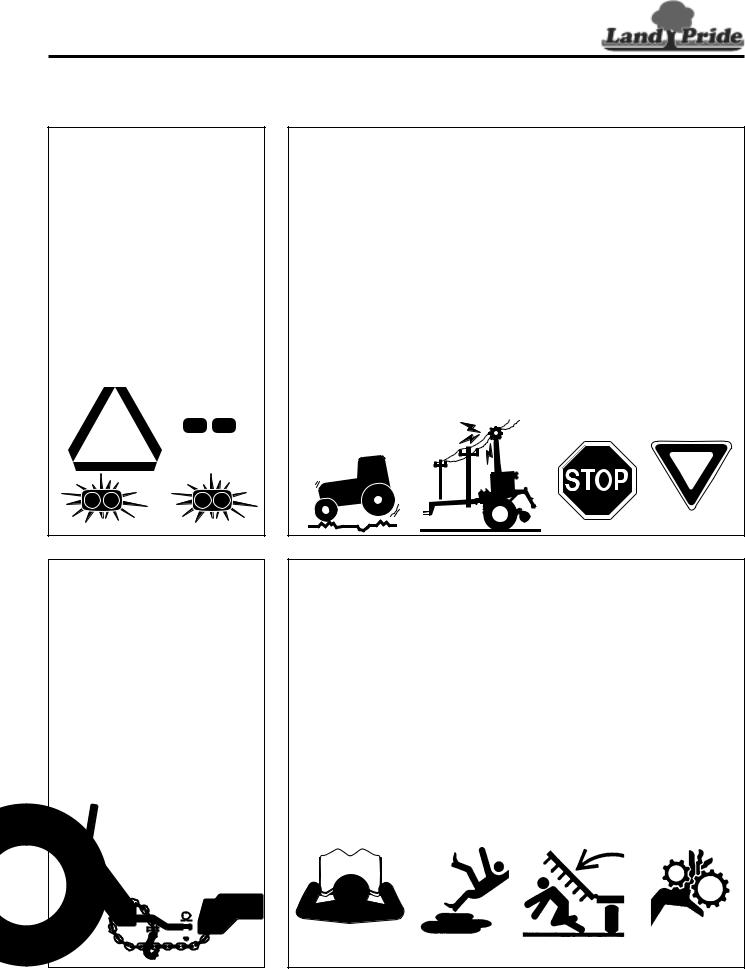
Table of Contents
Important Safety Information
These are common practices that may or may not be applicable to the products described in this manual.
Use Safety
Lights and Devices
▲Slow moving tractors, self-propelled equipment, and towed implements can create a hazard when driven on public roads. They are difficult to see, especially at night.
▲Flashing warning lights and turn signals are recommended whenever driving on public roads.
Transport
Machinery Safely
▲Comply with state and local laws.
▲Use towing vehicle and trailer of adequate size and capacity.
▲Secure equipment towed on a trailer with tie downs and chains.
▲Sudden braking can cause a trailer to swerve and upset. Reduce speed if trailer is not equipped with brakes.
▲Avoid contact with any over head utility lines or electrically charged conductors.
▲Engage parking brake when stopped on an incline.
▲Maximum transport speed for an attached implement is 20 mph. DO NOT EXCEED. Never travel at a speed which does not allow adequate control of steering and stopping. Some rough terrains require a slower speed.
▲As a guideline, use the following maximum speed weight ratios for an attached implement:
20 mph when weight of attached implement is less than or equal to the weight of machine towing the implement.
10 mph when weight of attached implement exceeds weight of machine towing implement but not more than double the weight.
▲IMPORTANT: Do not tow a load that is more than double the weight of the machine towing the load.
Use A Safety Chain
▲A safety chain will help control drawn machinery should it separate from the tractor drawbar.
▲Use a chain with the strength rating equal to or greater than the gross weight of the towed machinery.
▲Attach the chain to the tractor drawbar support or other specified anchor location. Allow only enough slack in the chain to permit turning.
▲Do not use safety chain for towing.
Practice Safe Maintenance
▲Understand procedure before doing work. Use proper tools and equipment, refer to Operator’s Manual for additional information.
▲Work in a clean dry area.
▲Lower attached implement to the ground, put tractor in park, turn off engine, and remove key before performing maintenance.
▲Allow implement to cool completely before working on it.
▲Disconnect battery ground cable (-) before servicing or adjusting electrical systems or before welding on implement.
▲Do not grease or oil implement while it is in operation.
▲Inspect all parts. Make certain parts are in good condition & installed properly.
▲Remove buildup of grease, oil, or debris.
▲Remove all tools and unused parts from implement before operation.
|
|
|
|
|
|
|
|
|
|
|
|
|
|
|
|
|
|
|
|
|
|
|
|
|
|
|
|
|
|
|
|
|
|
|
|
|
|
|
|
|
|
|
|
|
|
|
|
|
|
|
|
|
|
|
|
|
|
|
|
|
|
|
|
|
|
|
|
|
|
|
|
|
|
|
|
|
|
|
|
|
|
|
|
|
|
|
|
|
|
|
|
|
|
|
|
|
|
|
|
|
|
|
|
|
|
|
|
|
|
|
|
|
|
|
|
|
|
|
|
|
|
|
|
|
|
|
|
|
|
|
|
2 |
SB1051, SB1064, SB1574, & SB2584 with S/N 881640Snow Blowers 370-027M |
10/08/14 |
|||||||||||||||||||
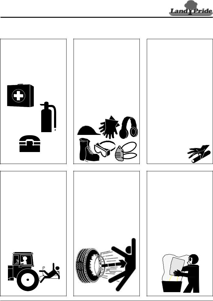
Table of Contents
Important Safety Information
These are common practices that may or may not be applicable to the products described in this manual.
Prepare for Emergencies
▲Be prepared if a fire starts.
▲Keep a first aid kit and fire extinguisher handy.
▲Keep emergency numbers for doctor, ambulance, hospital, and fire department near phone.
911
Keep Riders Off
Machinery
▲Never carry riders or use machinery as a personlift.
▲Riders obstruct operator’s view.
▲Riders could be struck by foreign objects or thrown from the machine.
▲Never allow children to operate equipment.
Wear
Protective Equipment
▲Wear protective clothing and equipment appropriate for the job. Clothing should be snug fitting without fringes and pull strings to avoid entanglement with moving parts.
▲Prolonged exposure to loud noise can cause hearing impairment or hearing loss. Wear suitable hearing protection such as earmuffs or earplugs.
▲Operating equipment safely requires the operator’s full attention. Avoid wearing radio headphones while operating machinery.
Avoid High
Pressure Fluids Hazard
▲Escaping fluid under pressure can penetrate the skin causing serious injury.
▲Avoid the hazard by relieving pressure before disconnecting hydraulic lines or performing work on the system.
▲Make sure all hydraulic fluid connections are tight and all hydraulic hoses and lines are in good condition before applying pressure to the system.
▲Use a piece of paper or cardboard, NOT BODY PARTS, to check for suspected leaks.
▲Wear protective gloves and safety glasses or goggles when working with hydraulic systems.
▲DO NOT DELAY. If an accident occurs, see a doctor familiar with this type of injury immediately. Any fluid injected into the skin or eyes must be treated within
a few hours or gangrene may result.
Tire Safety
▲Tire changing can be dangerous and should be preformed by trained personnel using the correct tools and equipment.
▲When inflating tires, use a clip-on chuck and extension hose long enough to allow you to stand to one side and NOT in front of or over the tire assembly. Use a safety cage if available.
▲When removing and installing wheels, use wheel handling equipment adequate for the weight involved.
Handle
Chemicals Properly
▲Protective clothing should be worn.
▲Handle all chemicals with care.
▲Follow instructions on container label.
▲Agricultural chemicals can be dangerous. Improper use can seriously injure persons, animals, plants, soil, and property.
▲Inhaling smoke from any type of chemical fire is a serious health hazard.
▲Store or dispose of unused chemicals as specified by the chemical manufacturer.
10/08/14 |
SB1051, SB1064, SB1574, & SB2584 with S/N 881640Snow Blowers 370-027M |
3 |
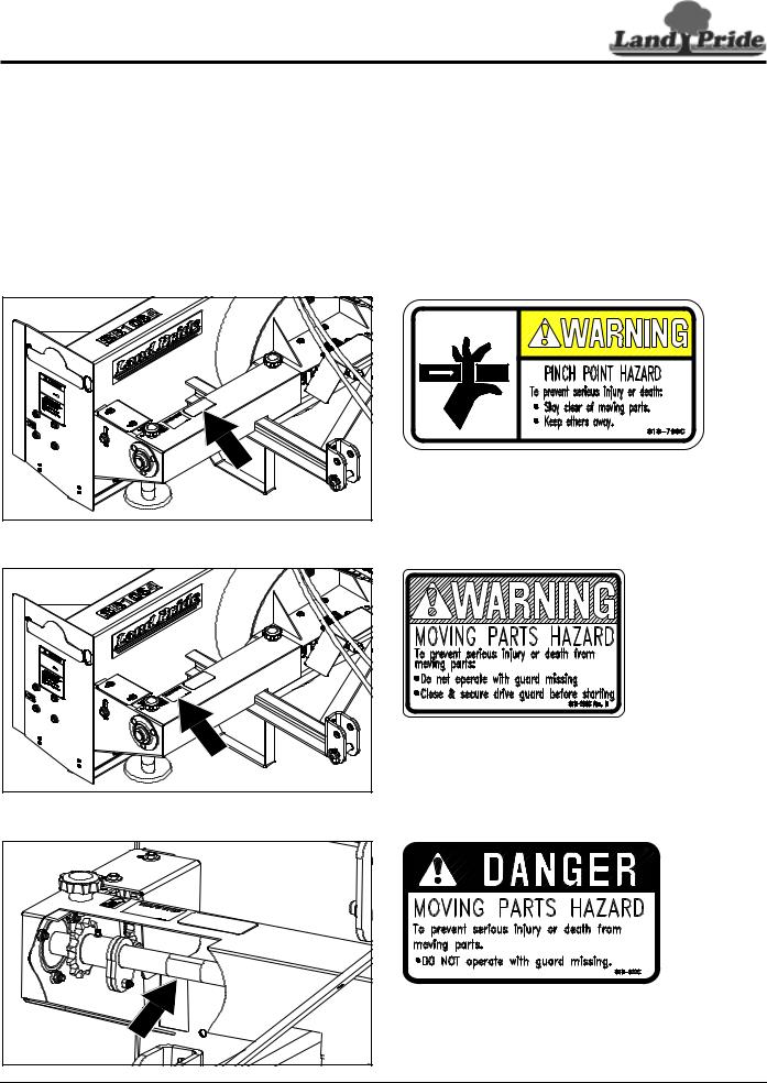
Table of Contents
Important Safety Information
Safety Labels
Your Snow Blower comes equipped with all safety labels in place. They were designed to help you safely operate your implement. Read and follow their directions.
1.Keep all safety labels clean and legible.
2.Refer to this section for proper label placement. Replace all damaged or missing labels. Order new labels from your nearest Land Pride dealer. To find your nearest dealer, visit our dealer locator at www.landpride.com.
3.Some new equipment installed during repair requires safety labels to be affixed to the replaced component as
specified by Land Pride. When ordering new components make sure the correct safety labels are included in the request.
4.Refer to this section for proper label placement. To install new labels:
a.Clean the area the label is to be placed.
b.Spray soapy water on the surface where the label is to be placed.
c.Peel backing from label. Press firmly onto the surface.
d.Squeeze out air bubbles with the edge of a credit card or with a similar type straight edge.
33247 |
33247 |
818-798C
Warning: Pinch Point Hazard
818-205C
Warning: Moving Parts Hazard
|
|
818-522C |
|
|
|
Danger: Moving Parts Hazard |
|
|
33249 |
|
|
4 |
SB1051, SB1064, SB1574, & SB2584 with S/N 881640Snow Blowers |
370-027M |
10/08/14 |

Table of Contents
Important Safety Information
33248 |
818-858C |
Warning: To Prevent Serious Injury or Death
33248 |
818-634C
Danger: Rotating Auger
|
33247 |
|
|
|
|
|
818-130C |
|
|
|
33248 |
Caution: To avoid Injury or Machine Damage |
|
|
10/08/14 |
SB1051, SB1064, SB1574, & SB2584 with S/N 881640Snow Blowers |
370-027M |
5 |
|
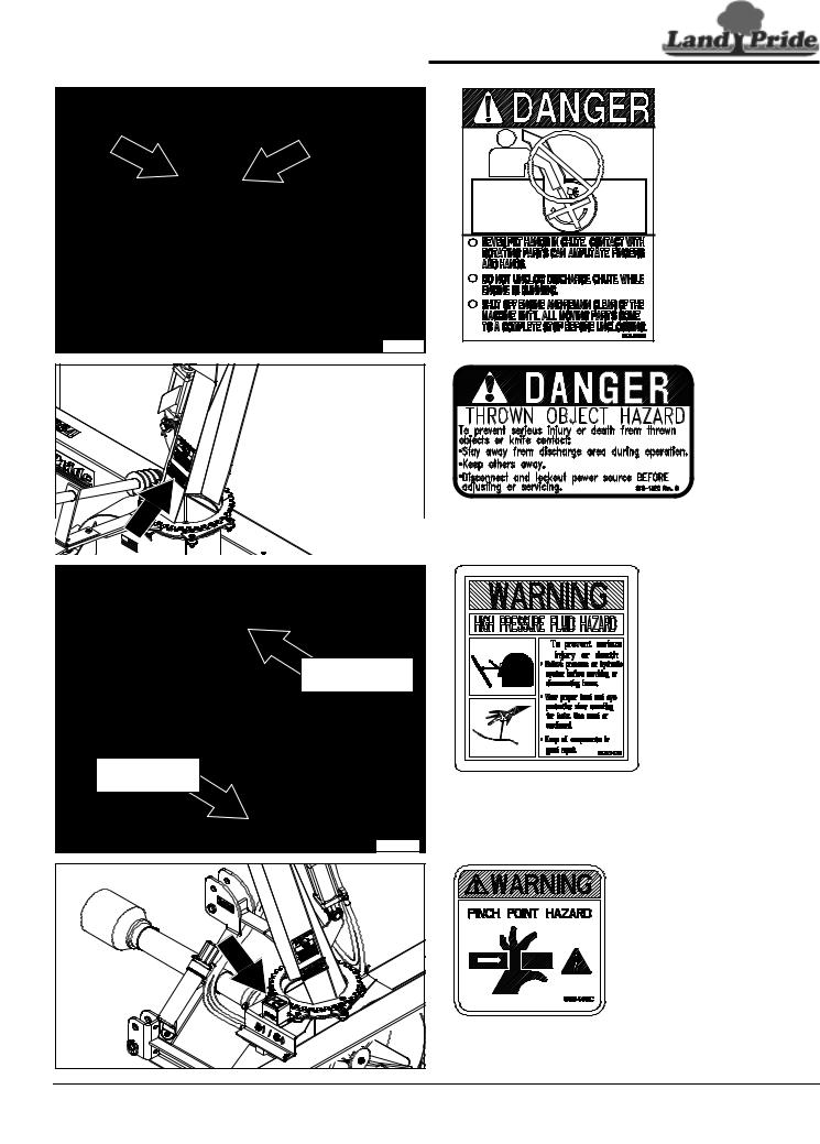
Table of Contents
Important Safety Information
33248 |
33248 |
848-840C
Danger: Hands in Chute
2-Places: On both sides of chute
Available after
Oct. 1, 2011
818-132C
Danger: Thrown Object Hazard
|
|
|
Hydraulic Cylinder |
|
|
|
|
Location |
|
|
|
Hydraulic Motor |
|
|
|
|
Location |
848-747C |
|
|
|
|
|
|
|
|
|
Warning: High Pressure Fluid Hazard |
|
|
|
|
Used only with hydraulic motor and hydraulic cylinders. |
|
|
|
|
35476 |
|
|
|
|
858-148C |
|
33234 |
|
Warning: Pinch Point Hazard |
|
|
|
|
|
|
|
6 |
SB1051, SB1064, SB1574, & SB2584 with S/N 881640Snow Blowers 370-027M |
10/08/14 |
||
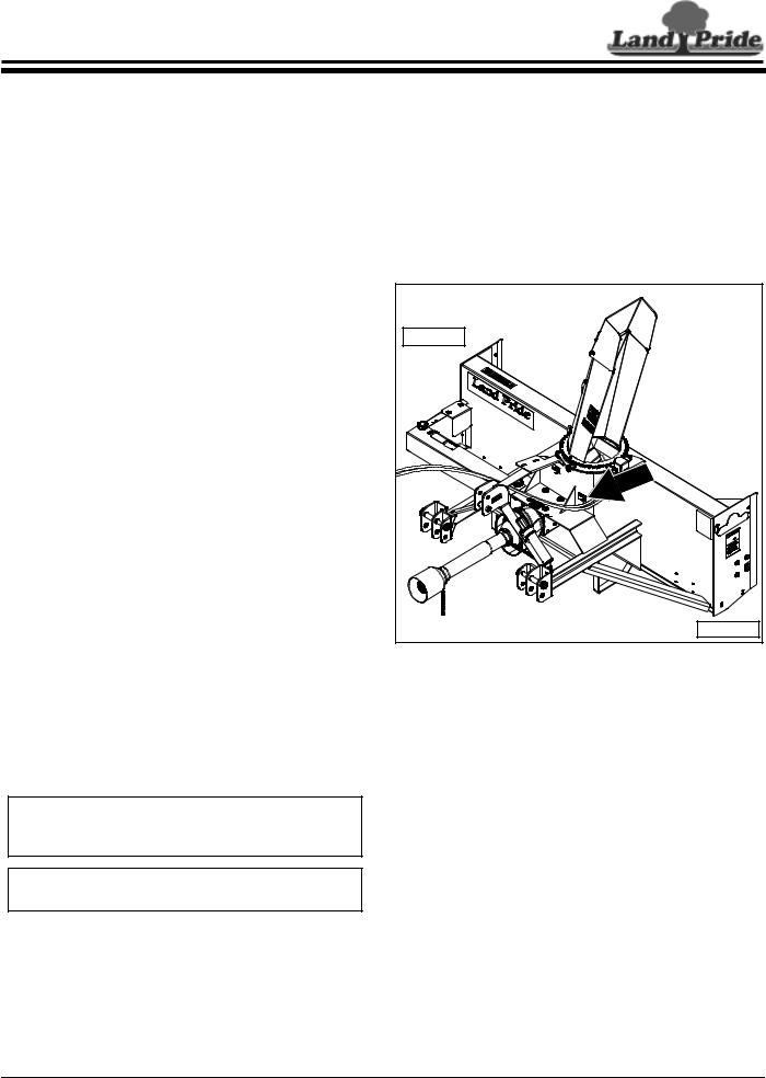
Table of Contents
Introduction
Land Pride welcomes you to the growing family of new product owners.
This Snow Blower has been designed with care and built by skilled workers using quality materials. Proper assembly, maintenance, and safe operating practices will help you get years of satisfactory use from this machine.
Application
Land Pride offers the SB10, SB15, and SB25 Series of residential Snow Blowers ranging from 51" up to 84" in width. They are 3-point rear mounted units for attaching to tractors ranging from 30 to 105 HP with Cat. l or Cat. ll hitches and are Quick-Hitch adaptable. These Snow Blowers are primarily designed to remove snow from driveways, parking lots, and sidewalks in general residential areas. Optional front cutting edge and inner or outer depth shoes can be purchased with all models to increase the life of the units.
See “Specifications & Capacities” on page 35 and
“Features & Benefits” on page 37 for additional information and performance enhancing options.
Using This Manual
•This Operator’s Manual is designed to help familiarize you with safety, assembly, operation, adjustments, troubleshooting, and maintenance. Read this manual and follow the recommendations to help ensure safe and efficient operation.
•The information contained within this manual was current at the time of printing. Some parts may change slightly to assure you of the best performance.
•To order a new Operator’s or Parts Manual, contact your authorized dealer. Manuals can also be downloaded, free-of-charge, from our website at www.landpride.com.
Pride dealer has trained personnel, repair parts, and equipment needed to service the implement.
Serial Number
Model No. _____________Serial No. _______________
For quick reference and prompt service, record model number and serial number in the spaces provided above and again on Warranty page 39. Always provide model and serial number when ordering parts and in all correspondences with your Land Pride dealer. Refer to Figure 1 for location of your serial number plate.
33105
Left Side |
Right Side
Serial Number Plate Location
Figure 1
Terminology
See Figure 1: “Right” or “Left” as used in this manual is determined by facing in the direction the machine will operate while in use unless otherwise stated.
Definitions
IMPORTANT: A special point of information related to the following topic. Land Pride’s intention is this information must be read & noted before continuing.
NOTE: A special point of information that the operator should be aware of before continuing.
Owner Assistance
The Online Warranty Registration should be completed by the dealer at the time of purchase. This information is necessary to provide you with quality customer service.
The parts on your Snow Blower have been specially designed by Land Pride and should only be replaced with genuine Land Pride parts. Contact a Land Pride dealer if customer service or repair parts are required. Your Land
Further Assistance
Your dealer wants you to be satisfied with your new Snow Blower. If for any reason you do not understand any part of this manual or are not satisfied with the service received, the following actions are suggested:
1.Discuss the matter with your dealership service manager making sure that person is aware of any problems you may have and has had the opportunity to assist you.
2.If you are still not satisfied, seek out the owner or general manager of the dealership, explain the problem, and request assistance.
3.For further assistance write to:
Land Pride Service Department
1525 East North Street
P.O. Box 5060
Salina, Ks. 67402-5060
E-mail address lpservicedept@landpride.com
10/08/14 |
SB1051, SB1064, SB1574, & SB2584 with S/N 881640Snow Blowers 370-027M |
7 |
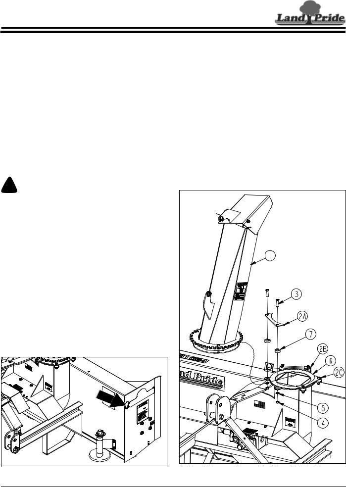
Table of Contents
Section 1: Standard Assembly & Set-up
Tractor Requirements
Tractor horsepower and hitch category should be within the range noted below. Tractors outside the horsepower range must not be used.
Tractor Horsepower Rating
SB10 Series . . . . . . . . . . . . . . . . . . . . .18 to 32 HP SB15 Series . . . . . . . . . . . . . . . . . . . . . . 30-59 HP SB25 Series . . . . . . . . . . . . . . . . . . . . . 43-105 HP
Hitch Type:
SB10 Series . . . . . . . . . . . . . . . . . . . . 3-Point Cat. I SB15 Series . . . . . . . . . . . . . . . . . . . . 3-Point Cat. I SB25 Series . . . . . . . . . . . . . . . . . 3-Point Cat. I & ll
PTO Speed. . . . . . . . . . . . . . . . . . . . . . . . . .540 RPM
Hydraulic Quick Disconnect Outlets (Optional)
Chute Rotational Adjustment. . . . . . . Duplex Outlet Chute Tilt Adjustment . . . . . . . . . . . . Duplex Outlet
Tractor Weight . . . . . . . . . . . . . . See Warning Below
! WARNING
Ballast weights may be required to maintain steering control. Refer to your tractor’s operator’s manual to determine proper ballast requirements.
Torque Requirements
Refer to “Torque Values Chart” on page 38 to determine correct torque values for common bolts. See
“Additional Torque Values” at bottom of chart for exceptions to standard torque values.
Dealer Set-up Instructions
When included, it is simpler to assemble the optional outer skid shoes or outer wear bars before removing the shipping crate. See “Skid Shoes, Outer” or “Wear Bars, Outer” on page 13 for detailed installation instructions.
Loading & Unloading
Refer to Figure 1-1:
There are two lifting holes (one on each end panel). These lift holes are provided for attaching a lift chain to the Snow Blower during loading and unloading.
33248 |
Lift Points
Figure 1-1
Chute Assembly
Refer to Figure 1-2:
1.Remove bearing strap (#2A) from Snow Blower housing. Keep cap screws (#3), bearing strap (#2A), chute bearings (#7), lock washers (#5), and hex nuts (#4) for reattachment of discharge chute (#1).
2.Position discharge chute (#1) so that it is facing straight back as shown.
3.Keep chute facing straight back. Slide base of discharge chute (#1) over UHMW chute bearing ring (#6) until base of chute is fully under the other two remaining bearing straps (#2B & 2C).
4.Reattach bearing strap (#2A) to Snow Blower housing by inserting existing 3/8"-16 x 1 1/2" cap screws (#3) through bearing strap (#2A), chute bearings (#7), and Snow Blower housing flange.
5.Secure bearing strap with existing lock washers (#5) and hex nuts (#4). Tighten nuts to the correct torque.
33255 |
Chute Assembly |
Figure 1-2 |
8 |
SB1051, SB1064, SB1574, & SB2584 with S/N 881640Snow Blowers 370-027M |
10/08/14 |
Table of Contents
Section 2: Optional Assembly & Set-up
33238 |
SB1051 Chute Rotation Powered By Manual Drive
Figure 2-1
Chute Rotation, Manual
For SB1051 Model
The following instructions are for Snow Blower model number SB1051 only.
Refer to Figure 2-1:
1.Slide 1 1/4" SAE flat washer (#7) onto spiral end of chute adjustment tube (#2).
2.Insert spiral end of chute adjustment tube (#2) through hole in mounting bracket (#1) as shown.
3.Insert opposite end of chute adjustment tube (#2) into hole in chute adjustment mount (#3).
4.Attach adjustment mount (#3) to Snow Blower mainframe as shown with two 3/8"-16 x 1 1/4" GR5 cap screws (#5) and hex flange lock nuts (#6). Tighten lock nut to the correct torque.
5.Drive 1/4" x 1 1/2" roll pin (#9) through holes in spiral end of chute adjustment tube (#2) until both ends of the roll pin extends equally through both holes in adjustment tube.
6.Insert rotation handle (#4) into chute adjustment tube (#2) and secure with wire retaining pin (#8). Make certain retaining wire is caught over end of pin to keep pin from falling out.
33237 |
SB1064, SB1574, & SB2584 |
Chute Rotation Powered By Manual Drive
Figure 2-2
Chute Rotation, Manual
For SB1064, SB1574, & SB2584 Models
The following instructions are for Snow Blower model numbers SB1064, SB1574, and SB2584 only.
Refer to Figure 2-2:
1.Slide 1 1/4" SAE flat washer (#7) onto spiral end of chute adjustment tube (#2).
2.Insert spiral end of chute adjustment tube (#2) through hole in mounting bracket (#1) as shown.
3.Insert opposite end of chute adjustment tube (#2) into hole in chute adjustment mount (#3).
4.Attach adjustment mount (#3) to Snow Blower mainframe as shown with two 3/8"-16 x 1 1/4" GR5 cap screws (#5) and hex flange lock nuts (#6). Tighten lock nut to the correct torque.
5.Drive 1/4" x 1 1/2" roll pin (#9) through holes in spiral end of chute adjustment tube (#2) until both ends of the roll pin extends equally through both holes in adjustment tube.
6.Insert rotation handle (#4) into chute adjustment tube (#2) and secure with wire retaining pin (#8). Make certain retaining wire is caught over end of pin to keep pin from falling out.
10/08/14 |
SB1051, SB1064, SB1574, & SB2584 with S/N 881640Snow Blowers 370-027M |
9 |
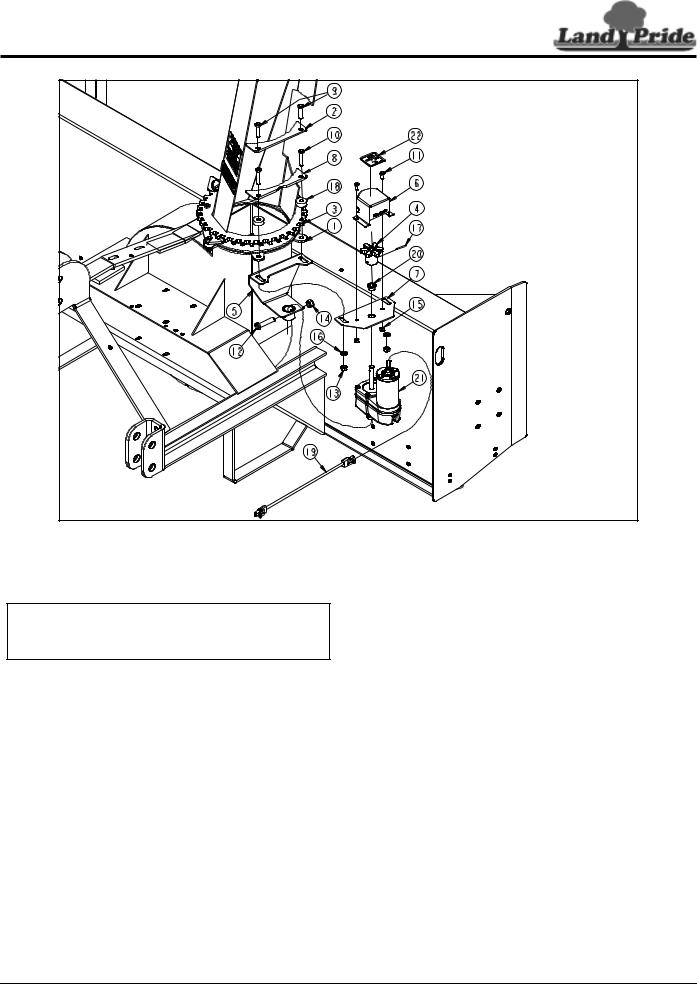
Table of Contents
Section 2: Optional Assembly & Set-up
33235 |
Chute Rotation Powered By Electric Motor
Figure 2-3
Chute Rotation, Electric Motor
Refer to Figure 2-3:
NOTE: Existing bearing strap (#2) is replaced with new bearing strap (#8) and bolts (#9) are replaced with new bolts (#10).
1.Rotate discharge chute clockwise until chute is against chute stop and can not be rotated further.
2.Remove and discard bolts (#9) and bearing strap (#2).
3.Press Oilite bushing (#20) into hole in electric bearing mount (#7).
4.Insert electric bearing mount (#7) over output shaft of electric motor (#21).
5.Insert base of electric motor (#21) into hub of electric motor mount (#5). Make sure bearing mount (#7) is beneath motor mount (#5).
6.Secure base of electric motor (#21) to hub of electric motor mount (#5) with 1/2"-13 x 2" GR5 bolt (#12) and hex lock nut (#14). Tighten lock nut to the correct torque.
7.Attach electric motor mount (#5) and electric bearing mount (#7) to underside of blower chute ring (#1) with new 3/8"-16 x 1 3/4" GR5 bolts (#10), new
bearing strap (#8), chute bearings (#18), lock washers (#16), and nuts (#13). Do not tighten nuts at this time.
8.Attach drive gear (#4) to electric motor (#21) with 1/8" x 1 1/4" long roll pin (#17). Drive roll pin fully into hub of drive gear (#4).
9.Adjust electric motor mount (#5) and electric bearing mount (#7) until drive sprocket (#4) has minimal clearance between drive sprocket (#4) and chute driven sprocket (#3).
10.Hold electric motor mount (#5) and electric bearing mount (#7) in the adjusted position and tighten 3/8"-16 GR5 bolts (#10) to the correct torque.
11.Attach gear cover (#6) to electric bearing mount (#7) with 1/4"-20 x 5/8" GR5 bolts (#11) and hex nylock nuts (#15). Tighten nylock nuts to the correct torque.
12.Attach pinch point picture decal (#22) to gear cover (#6). See “Safety Labels” on page 4 for installation instructions.
13.Attach electric harness (#19) to electric motor (#21).
14.Coil wire harness around Snow Blower mainframe for safe keeping.
15.Instructions for hooking-up wire harness to tractor is covered in “Section 3: Tractor Hook-up & Unhook” beginning on page 14.
10 SB1051, SB1064, SB1574, & SB2584 with S/N 881640Snow Blowers 370-027M |
10/08/14 |
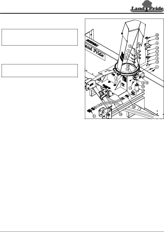
Table of Contents
Section 2: Optional Assembly & Set-up
Chute Rotation, Hydraulic Motor
Refer to Figure 2-4:
IMPORTANT: Adjustment screws on hydraulic motor are preset at the factory. Do not change factory settings. Changing factory settings can cause structural damage to the Snow Blower.
1.Rotate discharge chute clockwise until chute is against chute stop and can not be rotated further.
2.Remove bolts (#9), bearing strap (#2), chute bearings (#22), lock washers (#18), and nuts (#14).
NOTE: Existing bearing strap (#2) is reused with SB10 Series Snow Blowers. The SB15 and SB25 Series Snow Blowers uses new bearing strap (#7).
3. Attach hydraulic mounting plate (#8) as follows:
SB1051 & SB1064 Models
Attach mounting plate (#8) stamped 51/64 to blower chute ring (#1) with bolts (#9), existing strap (#2), chute bearings (#22), lock washers (#18), and hex nuts (#14). Do not tighten nuts at this time.
SB1574 Model
Attach mounting plate (#8) stamped 74 to blower chute ring (#1) with bolts (#9), new strap (#7), chute bearings (#22), lock washers (#18), and hex
nuts (#14). Do not tighten nuts at this time.
SB2584 Model
Attach mounting plate stamped 84 (#8) to blower chute ring (#1) with bolts (#9), new strap (#7), chute bearings (#22), lock washers (#18), and hex
nuts (#14). Do not tighten nuts at this time.
4.Continue to attach hydraulic mounting plate (#8) to the Snow Blower with 3/8"-16 x 3/4" GR5 carriage bolts (#11) and hex flange lock nuts (#15). Do not tighten lock nut at this time.
5.Attach hydraulic motor (#19) to hydraulic mounting plate (#8) with hex socket countersunk bolts (#12). Tighten countersunk bolts.
6.Install gear spacer (#5) over output shaft of hydraulic motor (#19).
7.Attach drive gear (#4) and key (#25) to output shaft of hydraulic motor (#19) with M6 x 1 x 35 GR8.8
bolt (#13) and spring lock washer (#17). Tighten M6 bolt to the correct torque.
8.Adjust hydraulic mounting plate (#8) until drive sprocket (#4) has minimal clearance between drive sprocket (#4) and chute driven sprocket (#3).
9.Hold hydraulic mounting plate (#8) in its adjusted position and tighten 3/8"-16 GR5 bolts (#9 & #11) to the correct torque.
35477 |
Chute Rotation Powered By Hydraulic Motor
Figure 2-4
10. Install gear cover (#6) as follows:
SB1051 & SB1064 Models
Attach gear cover (#6) stamped 370-534D to hydraulic mounting plate (#8) with 1/4"-20 x 5/8" GR5 bolts (#10) and hex nylock nuts (#16). Tighten nylock nuts to the correct torque.
SB1574 & SB2584 Models
Attach gear cover (#6) stamped 370-613D to hydraulic mounting plate (#8) with 1/4"-20 x 5/8" GR5 bolts (#10) and hex nylock nuts (#16). Tighten nylock nuts to the correct torque.
11.Screw 9/16" MORB x 9/16" MJIC adapters (#20) to ports in hydraulic motor (#19) until tight.
12.Screw 3/8" x 60" long hydraulic hoses (#23) to adapters (#20) until tight.
13.Screw quick disconnect couplings (#21) (couplings furnished by customer) to other end of hydraulic hoses (#23) until tight.
14.Attach High Pressure Fluid Decal 848-747C (#24) in the location shown. See “Safety Labels” on page 4 for installation instructions.
15.Coil Hydraulic hoses (#23) around Snow Blower mainframe for safe keeping.
10/08/14 |
SB1051, SB1064, SB1574, & SB2584 with S/N 881640Snow Blowers 370-027M |
11 |
Loading...