Land Pride Z60, Z72 User Manual

Steering Lever Extension Kit
Accu-Z Riding Mower Z52, Z60 & Z72 Series |
Manual No. 356-040M |
||
|
|
|
|
Before You Start
When you see this symbol, the subsequent
!instructions and warnings are serious - follow without exception. Your life and the lives of others depend on it!
IMPORTANT: Before you begin, read these instructions and check to be sure all parts and tools are accounted for. Please retain these installation instructions for future reference and parts ordering information.
Your Land Pride Steering Lever Extension Kit is exclusively designed for your Land Pride Accu-Z Riding Mower. Please read these installation instructions and your Accu-Z Operator’s Manual thoroughly before beginning. Especially read information relating to safety concerns. Also included in the Operator’s Manual is important information on operation, adjustment, troubleshooting, and maintenance for this attachment (some manual sections do not apply to all accessories).
A separate Parts Manual for replacement parts can be purchased from your dealer or available free of charge at www.landpride.com. Have model and serial numbers handy when placing an order.
Manual Part Numbers:
•Operator’s Manual . . . . . . . . . . . . . . . . . 356-005M
•Parts Manual . . . . . . . . . . . . . . . . . . . . . 356-005P
General Information
These assembly instructions apply to the following Accessory listed below:
356-039A STEERING LEVER EXTENSION KIT
Tools required:
•Safety Glasses
•Work Gloves
•Two 9/16" box end and/or open end wrenches
Assembly Instructions
Use the detailed listing on the back as a checklist to inventory parts received for your Steering Lever Extension Kit. Please contact your local Land Pride dealer for any missing hardware.
Initial Preparations
1.Park your Riding Mower on a flat surface, move steering levers to park, turn off engine and remove ignition key.
Refer to Figure 1:
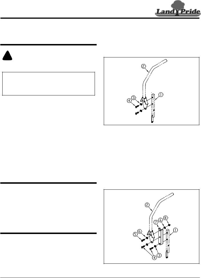
2.Disassemble steering levers (#2) from the steering arm mounts (#1). Keep steering levers and mounting hardware for reattachment.
Steering Lever Disassembly
Figure 1
Refer to Figure 2:
3.Attach the existing right hand steering lever (#2) and new extension bracket (#7) to the steering arm mount (#1) with two existing 3/8"-16 x 1 GR5 hex head cap screws (#4) and 3/8" flat washers (#3) and one new 3/8"-16 x 1" GR 5 hex head cap screw (#5), two 3/8" flat washers (#6) and 3/8" hex nut (#8) as shown.
4.Torque nuts to 35 ft. lbs.
5.Repeat steps 3 & 4 to attach the left hand steering lever.
Steering Lever Extension Assembly
Figure 2
© Copyright 2006 |
Pr inted |
2/13/06 |
1 |
 Loading...