


WS-9228U-IT
WS-9228U-IT
Wireless 915 MHz
Radio-controlled Weather Station
Instruction Manual
2
TABLE OF CONTENTS
Topic Page
Inventory of Contents/Additional Equipment
About WWVB
Quick Set-Up Guide
Detailed Set-Up Guide
Battery installation
Program Mode
Program Sequence and Default Settings
Function Keys
Setting the LCD Contrast
Setting the Time Zone
Daylight Saving Time Setting
Radio-controlled Time Setting
12/24-hour Time Setting
Setting the Time
Setting the Year, Day and Month
Setting the Snooze
Setting the Temperature Format
Setting the Forecast Sensitivity
Features
Weather Forecast Icons and Tendency Arrows
Indoor Temperature, Humidity, & Comfort
Level Indicator
Outdoor Temperatures and Humidity
Alarm Function (Setting Alarm 1 & 2) (S nooze & Silence)
Minimum & Maximum Records (Indoor,
Outdoor, & Resetting)
Additional Remote Control Sending Units (Set-Up, Viewing,
& Operation)
Mounting
Troubleshooting
Maintenance & Care
Specifications
Warranty Information
3
INVENTORY OF CONTENTS
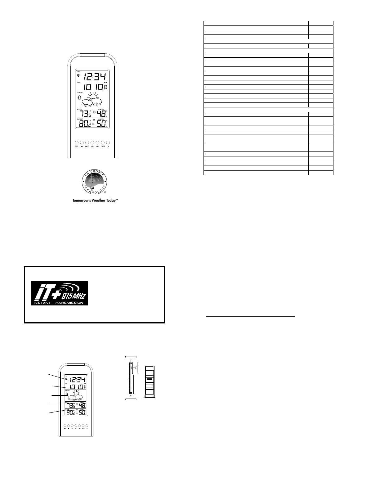
1. The Wireless Weather Station/ (Figure 1).
2. One remote temperature sensor with mounting brack et (Figure 2).
3. Two each, ½” Philips screws.
4. Instruction manual and warranty card.
ADDITIONAL EQUIPMENT (not included)
1. Two fresh AA 1.5V Alkaline batteries for the Wireless Weather Station.
2. Two fresh AA 1.5V Alkaline batteries for the remote temperature sensor.
3. One, Philips screwdriver for mounting.
Figure 1
Figure 2
Mounting
Bracket
TX29U-IT remote
temperature sensor
INSTANT TRANSMISSION is the state-
of-the-art new wire less transmission
technology, exclusively designed and
developed by LA CROSSE
TECHNOLOGY. INSTANT
TRANSMISSION offers you an
immediate update (every 4 seconds!) of
all your outdoor data measured from
the transmitters: follow your climatic
variations in real-time!
This product offers:
4
ABOUT WWVB (Radio Controlled Time)
The NIST (National Institute of Standards and Technology—Time and Frequency Division)
WWVB radio station is located in Ft. Collins, Colorado, and transmits the exact t ime and date
signal continuously throughout the United States at 60 kH z. The signal can be received up to
2,000 miles away through the internal antenna in the Weather Station. However, due to the
nature of the Earth’s Ionosphere, reception is v ery limited during daylight hours. The Weather
Station will search for a signal every night when reception is best. The WWVB radio station
derives its signal from the NIST Atomic clock in Boulder, Colorado. A team of atomic physicists
is continually measuring every second, of every day, to an accuracy of ten billionths of a second
per day. These physicists have created an international standard, measuring a second as
9,192,631,770 vibrations of a Cesium-133 atom in a vacuum. For more information on the
atomic clock and WWVB please see the NIST website at
http://www.boulder.nist.gov/timefreq/stations/wwvb.htm
.
QUICK SET-UP GUIDE
Hint: Use good quality Alkaline Batteries and avoid rechargeable batteri es.
1. Have the Wireless Weather Station and remote tem perature sensor 3 to 5 feet apart.
2. Batteries should be out of both units for 10 minu tes.
3. Place the batteries into the remote temperature sensor first then into the indoor
weather station.
(All remote temperature sensors must be started b efore the Wireless Weather Station)
4. DO NOT PRESS ANY BUTTONS FOR 15 MINUTES.
In this time the Wireless Weather Station and remote temperature sensor will start to talk to each
other and the display will show both the indoor temperature and humidity, and an outdoo r
temperature. If the Wireless Weather Station does not display both temperatures after the 15
minutes please retry the set up as stated above. A fter both indoor and outdoor temperatures are
displayed for 15 minutes you can place your remote temperature sensor outdoor and set your
time.
The remote temperature sensor should be pla ced in a dry, shaded area. The temperature
sensor has a range of 330 feet. Keep in mind that the 330 feet is in open air with no
obstructions and that radio waves DO NOT curve around objects. Actual transmission range will
vary depending on what is in the path of the signal. Each obstruction (roof, walls, floors,
ceilings, thick trees, etc.) will effectively cut signal range in half.
Example: A Wireless Weather Station with a 330 feet range is mounted on an interior wall, so
that the signal has to pass through one interior wall, one exterior wall, and across the 10 feet
width of the room between the 2 walls. The first wall will reduce the range to 165 feet, and the
second wall will reduce the range to 87 feet. Factoring in the 10 foot room, this leaves a
maximum of 77 feet of remaining signal range.
This allowance is typically enough for a frame wall with non-metallic siding; however certain
materials can reduce range even further. Metal siding, stucco, and some types of glass can
reduce signal range by as much as ¾ or more, compared t o the ½ reduction typical of most
obstructions. It is possible to receive a signal th rough these materials, however maximum range
will be much less due to their tendency to absorb or reflect a much larger portion of the sensor’s
signal.
5
To complete the set up of your Wireless Weather Station aft er the 15 minutes have passed
please follow the steps that follow in the Detailed Set-Up Guide.
DETAILED SET-UP GUIDE
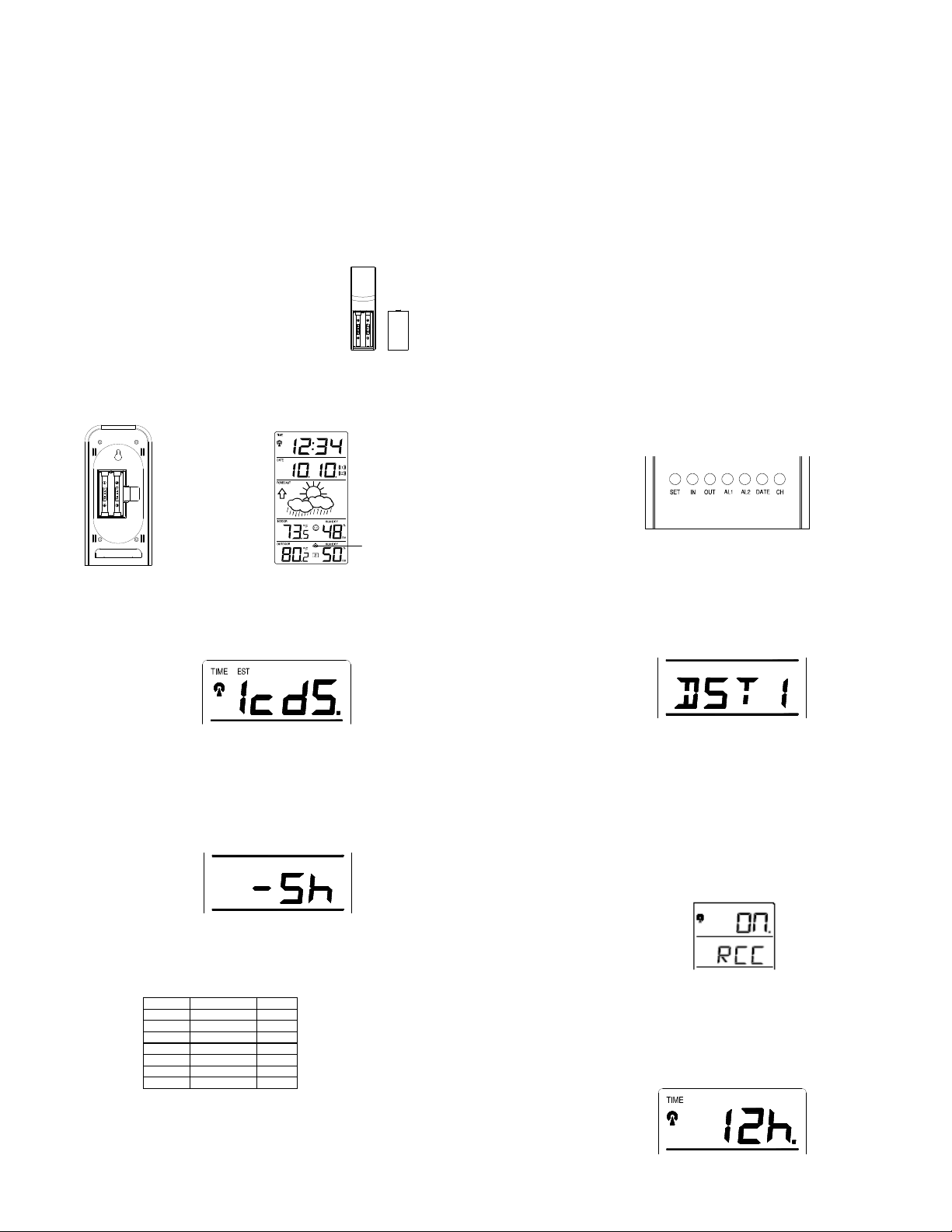
I. BATTERY INSTALLATION (When one temperature sensor is being used)
1. First, insert the batteries to the temperature se nsor (see “A. Remote Temperature
Sensor” below).
2. Within 30 seconds of powering up the sensor, insert the b atteries to the Weather
Station (see “B. Wireless Weather Station” below). Once the batteries are in place, all
segments of the LCD will light up briefly. Following the indoor temperature and
humidity, and the time as 12:00 will be displayed. If they are not shown in LCD after 60
seconds, remove the batteries and wait for at least 60 se conds before reinserting
them. Once the indoor data is displayed user may proceed to the next step.
3. After the batteries are inserted, the Weather Station will start receiving data signal
from the sensor. The outdoor temperature shoul d then be displayed on the Weather
Station. If this does not happen after 2 minutes, the batteries will need to be removed
from both units and reset from step 1 and the signal reception icon is no longer shown.
A. REMOTE TEMPERATURE SENSOR
1. Remove the mounting bracket. The bracket snaps o n
and off easily.
2. Remove the battery cover, by sliding the cover down.
3. Observing the correct polarity install 2 AA batteries. The
batteries will fit tightly (to avoid start-up problems make
sure they do not spring free).
4. Replace the battery cover by sliding upwards. Be sure
battery cover is on securely.
B. WIRELESS WEATHER STATION
1. Remove the battery cover. To do this, insert a solid obje ct in the space provided
at the lower-central position of the battery cover, then pus h up and pull out on the
battery cover.
2. Observe the correct polarity, and install 2 AA batteries.
3. Replace the battery cover.
Battery
Cover
Sensor signal
reception icon*
6
* When the signal is successfully received by the Weather Station, the icon will be
switched on. (If not successful, the icon will not be shown in LCD) So the user can
easily see whether the last reception was successful (icon on) or not (icon off). On the
other hand, the short blinking of the icon shows that a reception is being done now.
If the signal reception is not successful on the first frequency (915MHz) for 45 seconds, the
frequency is changed to 920MHz and the learning is tried another 45 seconds. If still not
successful the reception is tried for 45 seconds on 910MHz. This will also be done for re-
synchronization.
PROGRAM MODE
Programming Note: If 30 seconds is allowed to pass, or the CH button is pressed
during the programming mode, the unit will confirm/set the last information entered—
the display will stop flashing and return to normal time-date readings. If you don’t leave
the program mode during the programming of sections III through XII, you can
advance to step 4 of the next program setting. If you do leave the program setting (or
want to program a specific setting) follow each instructional step to program that
setting.
I. PROGRAMMING SEQUENCE AND DEFAULT SETTINGS
The programming sequence and default (factory) settings are as follows:
LCD Contrast 5
Time Zone -5 (Eastern)
Daylight Saving Time 1 (on)
Radio-controlled time reception ON
12/24-hour time 12
Time 12:00
Year 2005
Day and Month 1.1.
Snooze (this function not used) 10
Temperature Format F
Forecast Sensitivity 2
Please note that while there is a snooze adjustment in the programming this is an
unused function as there is no alarm on the indoor weather station.
II. FUNCTION KEYS
The function keys are located on the front of the unit directly below the LCD.
III. SETTING THE LCD CONTRAST
1. Press and hold the SET button for 5 seconds.
2. “LCD” will show in the time LCD and the number setting will flash.
7
Note: There are 8 LCD contrast levels to choose from—“Lcd 0” is the
lightest, and “Lcd 7” is the darkest.
3. Press and release the IN button to select the level you desire.
4. Press and release the SET button to confirm and advance to the Time
Zone setting.
IV. TIME ZONE SETTING
1. Press and hold the SET button for 5 seconds.
2. “LCD” will show in the time LCD and the number setting will flash.
3. Press and release the SET button again.
4. The time zone will flash in the date LCD.
5. Press and release the IN button to select your time zone.
Note: When a time zone for the U.S. is selected the corresponding
abbreviation will appear above the time (please see the table on the next
page). It is possible to select any time zone from –1 2 GMT to +12 GMT (for
example to see the time in another country)
TIME ZONES
GMT 0
ALT Atlantic -4
EST Eastern -5
CST Central -6
MST Mountain -7
PST Pacific -8
ALA Alaska -9
HAW Hawaii -10
6. Press and release the SET button to confirm and advanc e to the
Daylight Saving Time setting.
V. DAYLIGHT SAVING TIME (DST) SETTING
1. Press and hold the SET button for 5 seconds.
2. “LCD” will show in the time LCD and the number setting will flash.
3. Press and release the SET button twice.
4. “DST” will appear in the date LCD and either “1” or “0” will flash.
8
5. Press and release the IN button to select DST on or off.
“DST 0” indicates that the feature is off and the WWVB will not change
times automatically. “DST 1” indicates that the feature is on and the WWVB
will change times automatically.
Note: Some locations (Arizona) do not follow Daylight Saving Time, and
should select “DST 0.”
6. Press and release the SET button to confirm and advance to the radio-
controlled time on/off setting.
VI. RADIO-CONTROLLED TIME ON/OFF SETTING
1. Press and hold the SET button for 5 seconds.
2. “LCD” will show in the time LCD and the number setting will flash.
3. Press and release the SET button three times.
4. “RCC” will appear in the date LCD and “ON” or “OFF” will flash in the
time LCD.
5. Press and release the IN button to select radio-controlled time on or
off.
6. Press and release the SET button to confirm and advanc e to the
12/24-hour time setting.
VII. 12 OR 24 HOUR TIME SETTING
1. Press and hold the SET button for 5 seconds.
2. “LCD” will show in the time LCD and the number setting will flash.
3. Press and release the SET button four times.
4. “12h” or “24h” will flash in the time LCD.
5. Press and release the IN button to select 12 or 24-hour time format.
 Loading...