


DP-420/PF-420 DF-420/JS-420 FAX System (R)
SERVICE
MANUAL
Published in May 2009
3MZSM060
First Edition
CAUTION
RISK OF EXPLOSION IF BATTERY IS REPLACED BY AN INCORRECT TYPE. DISPOSE OF USED BATTERIES ACCORDING TO THE INSTRUCTIONS.
It may be illegal to dispose of this battery into the municipal waste stream. Check with your local solid waste officials for details in your area for proper disposal.
ATTENTION
IL Y A UN RISQUE D’EXPLOSION SI LA BATTERIE EST REMPLACEE PAR UN MODELE DE TYPE INCORRECT. METTRE AU REBUT LES BATTERIES UTILISEES SELON LES INSTRUCTIONS DONNEES.
Il peut être illégal de jeter les batteries dans des eaux d’égout municipales. Vérifiez avec les fonctionnaires municipaux de votre région pour les détails concernant des déchets solides et une mise au rebut appropriée.
Revision history
Revision |
Date |
Replaced pages |
Remarks |
|
|
|
|
|
|
|
|

This page is intentionally left blank.

Safety precautions
This booklet provides safety warnings and precautions for our service personnel to ensure the safety of their customers, their machines as well as themselves during maintenance activities. Service personnel are advised to read this booklet carefully to familiarize themselves with the warnings and precautions described here before engaging in maintenance activities.

Safety warnings and precautions
Various symbols are used to protect our service personnel and customers from physical danger and to prevent damage to their property. These symbols are described below:
 DANGER: High risk of serious bodily injury or death may result from insufficient attention to or incorrect compliance with warning messages using this symbol.
 WARNING: Serious bodily injury or death may result from insufficient attention to or incorrect compliance with warning messages using this symbol.
 CAUTION: Bodily injury or damage to property may result from insufficient attention to or incorrect compliance with warning messages using this symbol.
Symbols
The triangle ( ) symbol indicates a warning including danger and caution. The specific point of attention is shown inside the symbol.
General warning.
Warning of risk of electric shock.
Warning of high temperature.
 indicates a prohibited action. The specific prohibition is shown inside the symbol.
General prohibited action.
Disassembly prohibited.
 indicates that action is required. The specific action required is shown inside the symbol.
General action required.
Remove the power plug from the wall outlet.
Always ground the copier.

1.Installation Precautions
 WARNING
•Do not use a power supply with a voltage other than that specified. Avoid multiple connections to one outlet: they may cause fire or electric shock. When using an extension cable, always check that it is adequate for the rated current. .............................................................................................
•Connect the ground wire to a suitable grounding point. Not grounding the copier may cause fire or electric shock. Connecting the earth wire to an object not approved for the purpose may cause explosion or electric shock. Never connect the ground cable to any of the following: gas pipes, lightning rods, ground cables for telephone lines and water pipes or faucets not approved by the proper authorities. ............................................................................................................................
 CAUTION:
•Do not place the copier on an infirm or angled surface: the copier may tip over, causing injury. .......
•Do not install the copier in a humid or dusty place. This may cause fire or electric shock. ................
•Do not install the copier near a radiator, heater, other heat source or near flammable material.
This may cause fire. .........................................................................................................................
•Allow sufficient space around the copier to allow the ventilation grills to keep the machine as cool as possible. Insufficient ventilation may cause heat buildup and poor copying performance. ...........
•Always handle the machine by the correct locations when moving it. ...............................................
•Always use anti-toppling and locking devices on copiers so equipped. Failure to do this may cause the copier to move unexpectedly or topple, leading to injury. ...........................................................
•Avoid inhaling toner or developer excessively. Protect the eyes. If toner or developer is accidentally ingested, drink a lot of water to dilute it in the stomach and obtain medical attention immediately. If it gets into the eyes, rinse immediately with copious amounts of water and obtain medical attention. ......................................................................................................................................
•Advice customers that they must always follow the safety warnings and precautions in the copier’s instruction handbook. .....................................................................................................................

2.Precautions for Maintenance
 WARNING
•Always remove the power plug from the wall outlet before starting machine disassembly. ...............
•Always follow the procedures for maintenance described in the service manual and other related brochures. .......................................................................................................................................
•Under no circumstances attempt to bypass or disable safety features including safety mechanisms and protective circuits. .....................................................................................................................
•Always use parts having the correct specifications. ..........................................................................
•Always use the thermostat or thermal fuse specified in the service manual or other related brochure when replacing them. Using a piece of wire, for example, could lead to fire or other serious accident. ..........................................................................................................................................
•When the service manual or other serious brochure specifies a distance or gap for installation of a part, always use the correct scale and measure carefully. ................................................................
•Always check that the copier is correctly connected to an outlet with a ground connection. .............
•Check that the power cable covering is free of damage. Check that the power plug is dust-free. If it is dirty, clean it to remove the risk of fire or electric shock. ..............................................................
•Never attempt to disassemble the optical unit in machines using lasers. Leaking laser light may damage eyesight. ...........................................................................................................................
•Handle the charger sections with care. They are charged to high potentials and may cause electric shock if handled improperly. ............................................................................................................
CAUTION
•Wear safe clothing. If wearing loose clothing or accessories such as ties, make sure they are safely secured so they will not be caught in rotating sections. ..........................................................
•Use utmost caution when working on a powered machine. Keep away from chains and belts. ........
•Handle the fixing section with care to avoid burns as it can be extremely hot. ..................................
•Check that the fixing unit thermistor, heat and press rollers are clean. Dirt on them can cause abnormally high temperatures. ........................................................................................................

•Do not remove the ozone filter, if any, from the copier except for routine replacement. ....................
•Do not pull on the AC power cord or connector wires on high-voltage components when removing them; always hold the plug itself. .....................................................................................................
•Do not route the power cable where it may be stood on or trapped. If necessary, protect it with a cable cover or other appropriate item. .............................................................................................
•Treat the ends of the wire carefully when installing a new charger wire to avoid electric leaks. ........
•Remove toner completely from electronic components. ...................................................................
•Run wire harnesses carefully so that wires will not be trapped or damaged. ....................................
•After maintenance, always check that all the parts, screws, connectors and wires that were removed, have been refitted correctly. Special attention should be paid to any forgotten connector, trapped wire and missing screws. ...................................................................................................
•Check that all the caution labels that should be present on the machine according to the instruction handbook are clean and not peeling. Replace with new ones if necessary. ......................................
•Handle greases and solvents with care by following the instructions below: .....................................
·Use only a small amount of solvent at a time, being careful not to spill. Wipe spills off completely.
·Ventilate the room well while using grease or solvents.
·Allow applied solvents to evaporate completely before refitting the covers or turning the power switch on.
·Always wash hands afterwards.
•Never dispose of toner or toner bottles in fire. Toner may cause sparks when exposed directly to fire in a furnace, etc. .......................................................................................................................
•Should smoke be seen coming from the copier, remove the power plug from the wall outlet immediately. ............................................................................................................................................
3.Miscellaneous
 WARNING
•Never attempt to heat the drum or expose it to any organic solvents such as alcohol, other than the specified refiner; it may generate toxic gas. .....................................................................................

This page is intentionally left blank.
DP-420
First Edition
|
|
|
3MX |
|
|
CONTENTS |
|
1-1 Specifications |
|
||
1-1-1 Specifications.......................................................................................................................................... |
1-1-1 |
||
1-1-2 |
Parts names............................................................................................................................................ |
1-1-2 |
|
1-1-3 |
Machine cross section ............................................................................................................................ |
1-1-3 |
|
1-2 Installation |
|
||
1-2-1 |
Installation environment .......................................................................................................................... |
1-2-1 |
|
1-2-2 Unpacking ............................................................................................................................................... |
1-2-2 |
||
|
(1) |
Unpacking ......................................................................................................................................... |
1-2-2 |
|
(2) |
Removing the tapes and the spacer.................................................................................................. |
1-2-3 |
1-3 Maintenance Mode |
|
||
1-3-1 |
Maintenance mode (operation panel is a 7-segment type)..................................................................... |
1-3-1 |
|
|
(1) |
Executing a maintenance item .......................................................................................................... |
1-3-1 |
|
(2) |
Maintenance mode item list............................................................................................................... |
1-3-2 |
|
(3) |
Contents of maintenance mode items............................................................................................... |
1-3-3 |
1-3-2 |
Maintenance mode (operation panel is an LCD type)........................................................................... |
1-3-15 |
|
|
(1) |
Executing a maintenance item ........................................................................................................ |
1-3-15 |
|
(2) |
Maintenance mode item list............................................................................................................. |
1-3-16 |
|
(3) |
Contents of maintenance mode items............................................................................................. |
1-3-17 |
1-4 Troubleshooting |
|
||
1-4-1 |
Original misfeed detection ...................................................................................................................... |
1-4-1 |
|
|
(1) |
Original misfeed indication ................................................................................................................ |
1-4-1 |
|
(2) |
Original misfeed detection conditions................................................................................................ |
1-4-1 |
|
(3) |
Paper misfeeds ................................................................................................................................. |
1-4-3 |
1-4-2 Self-diagnosis ......................................................................................................................................... |
1-4-4 |
||
|
(1) |
Self-diagnostic function (operation panel is a 7-segment type)......................................................... |
1-4-4 |
|
(2) |
Self diagnostic codes (operation panel is a 7-segment type)............................................................ |
1-4-4 |
|
(3) |
Self-diagnostic function (operation panel is an LCD type) ................................................................ |
1-4-4 |
|
(4) |
Self diagnostic codes (operation panel is an LCD type).................................................................... |
1-4-4 |
1-4-3 |
Electric problems .................................................................................................................................... |
1-4-5 |
|
1-4-4 |
Mechanical problems .............................................................................................................................. |
1-4-6 |
|
1-5 Assembly and Disassembly |
|
||
1-5-1 |
Precautions for assembly and disassembly............................................................................................ |
1-5-1 |
|
|
(1) |
Precautions ....................................................................................................................................... |
1-5-1 |
1-5-2 |
Original feed section ............................................................................................................................... |
1-5-2 |
|
|
(1) |
Detaching and refitting the DP forwarding pulley and DP feed pulley............................................... |
1-5-2 |
|
(2) |
Detaching and refitting the DP separation pad.................................................................................. |
1-5-5 |
1-5-3 |
Image adjustment ................................................................................................................................... |
1-5-6 |
|
|
(1) |
Adjusting the angle of leading edge .................................................................................................. |
1-5-6 |
|
(2) |
Adjusting the angle of trailing edge ................................................................................................... |
1-5-8 |
2-1 Mechanical construction |
|
||
2-1-1 |
Mechanical construction ......................................................................................................................... |
2-1-1 |
|
|
(1) |
Operation of original switchback ....................................................................................................... |
2-1-3 |
2-2 Electrical Parts Layout |
|
||
2-2-1 |
Electrical parts layout.............................................................................................................................. |
2-2-1 |
|
|
(1) |
PWBs ................................................................................................................................................ |
2-2-1 |
|
(2) |
Switches and sensors ....................................................................................................................... |
2-2-2 |
|
(3) |
Motors ............................................................................................................................................... |
2-2-3 |
|
(4) |
Solenoids........................................................................................................................................... |
2-2-4 |
2-3 Operation of the PWBs
2-3-1 DP main PWB ......................................................................................................................................... |
2-3-1 |
3MX
2-4 Appendixes
List of maintenance parts........................................................................................................................ |
2-4-1 |
Periodic maintenance procedures .......................................................................................................... |
2-4-2 |
Wiring diagram........................................................................................................................................ |
2-4-4 |
3MX
1-1-1 Specifications
Type ................................................ |
Duplex sheet-through document feeder |
Original feed method ...................... |
Automatic feed |
Original weight ................................ |
Single-sided original mode: 45 to 160 g/m2 |
|
Double-sided original mode: 50 to 120 g/m2 |
Original type.................................... |
Sheet originals |
Original size .................................... |
A3 to A5R/Ledger to StatementR |
Original No. of sheets ..................... |
50 sheets or less (50 to 80 g/m2) |
|
Mixed original sizes: 30 sheets or less (50 to 80 g/m2) |
Original scanning speed ................. |
53.5 to 107 mm/s |
Power source.................................. |
Electrically connected to the machine |
Dimensions ..................................... |
559 (W) x 487 (D) x 131 (H) mm |
|
22" (W) x 19 3/16" (D) x 5 3/16" (H) |
Weight............................................. |
7 kg/15.4 lbs or less |
NOTE: These specifications are subject to change without notice.
1-1-1
3MX
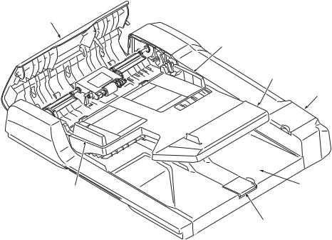
1-1-2 Parts names
4
2
1
6
 3
3
2
5
Figure 1-1-1
1.Original table
2.Original width guides
3.Original eject table
4.Document processor top cover
5.Original stopper
6.Cleaning cloth compartment
1-1-2
3MX
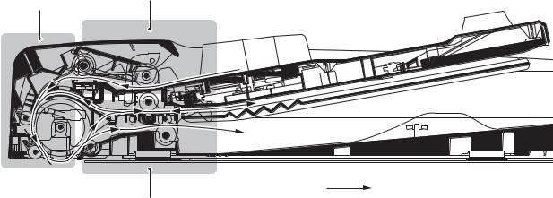
1-1-3 Machine cross section
1
2
Original path
3
Figure 1-1-2 Machine cross section
1.Original feed section
2.Original conveying section
3.Original switchback section
1-1-3

3MX
This page is intentionally left blank.
1-1-4
3MX
1-2-1 Installation environment
Installation location (Be based on the machine establishment place.)
Avoid direct sunlight or bright lighting. Ensure that the photoconductor will not be exposed to direct sunlight or other strong light when removing paper jams.
Avoid locations subject to high temperature and high humidity or low temperature and low humidity; an abrupt change in the environmental temperature; and cool or hot, direct air.
Avoid places subject to dust and vibrations.
Choose a surface capable of supporting the weight of the machine.
Place the machine on a level surface (maximum allowance inclination: 1°).
Avoid air-borne substances that may adversely affect the machine or degrade the photoconductor, such as mercury, acidic of alkaline vapors, inorganic gasses, NOx, SOx gases and chlorine-based organic solvents.
Select a well-ventilated location.
1-2-1

3MX
1-2-2 Unpacking
(1) Unpacking
|
|
Figure 1-2-1 Unpacking |
|
|
|
1. |
Document processor |
9. |
Plastic bag |
17. |
Angle adjusting plate |
2. |
Outer case |
10. |
Cleaning cloth |
18. |
Plastic bag |
3. |
Inner case |
11. |
Tray spacer |
19. |
Installation guide |
4. |
Rear upper pad |
12. |
Plastic bag |
20. |
Film |
5. |
Rear lower pad |
13. |
Original mat |
21. |
Label A |
6. |
Front pad |
14. |
Plastic bag |
22. |
Label B (220 V - 240 V |
7. |
Spacer |
15. |
M4 x 14 screws |
|
specifications only) |
8. |
Plastic sheet |
16. |
Pins |
|
|
Caution: See the Installation Guide for installation.
1-2-2
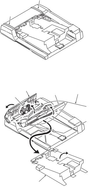
(2) Removing the tapes and the spacer
Procedure
1. Remove two tapes.
2.Open the document processor top cover.
3.Raise the DP feed pulley unit.
4.Open the spacer.
5.Raise the original table.
6.Remove the spacer.
7.Remove the plastic bag.
3MX
Tape
Tape
Figure 1-2-2
Document processor top cover
Original table |
Plastic bag |
DP feed pulley unit
Spacer
Figure 1-2-3
1-2-3
3MX
This page is intentionally left blank.
1-2-4
3MX
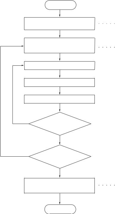
1-3-1 Maintenance mode (operation panel is a 7-segment type)
The machine is equipped with a maintenance function which can be used to maintain and service the machine.
(1) Executing a maintenance item
Start
Enter “10871087” using the numeric keys.
Enter the maintenance item number using the zoom +/- keys or numeric keys.
Press the start key.
The selected maintenance item is run.
Press the stop/clear key.
Yes |
Repeat the same |
|
|
|
maintenance item? |
|
No |
Yes |
Run another maintenance |
|
|
|
item? |
|
No |
|
Enter “001” using the zoom |
|
+/- keys or numeric keys |
|
and press the start key. |
Maintenance mode is entered.
The maintenance item is selected.
Maintenance mode is exited.
End
1-3-1
3MX
(2) Maintenance mode item list
Section |
Item |
Content of maintenance item |
Initial |
|
No. |
setting* |
|||
|
|
|||
|
|
|
|
|
General |
U019 |
Displaying the ROM version |
- |
|
|
|
|
|
|
Optical |
U068 |
Adjusting the scanning position for originals from the DP |
0*1 |
|
|
U070 |
Adjusting the DP magnification |
0/0*1 |
|
|
U071 |
Adjusting the DP scanning timing |
0/0/0/0*1 |
|
|
U072 |
Adjusting the DP center line |
0/0*1 |
|
|
U074 |
Adjusting the DP input light luminosity |
1*1 |
|
|
U076 |
Adjusting the DP automatically |
- |
|
|
U087 |
Setting DP reading position modification operation |
ON/35*1 |
|
Operation |
U203 |
Checking DP operation |
- |
|
panel and |
|
|
|
|
U243 |
Checking the operation of the DP motors |
- |
||
support |
||||
|
|
|
||
U244 |
Checking the DP switches |
- |
||
equipment |
||||
|
|
|
|
|
Image |
U404 |
Adjusting margins for scanning an original from the DP |
2.0/3.0/2.0/2.0*1 |
|
processing |
|
|
|
|
|
|
|
|
|
Other |
U905 |
Checking/clearing counts by optional devices |
- |
|
|
U942 |
Setting of deflection for feeding from DP |
0/0*1 |
|
|
|
|
|
*Initial setting for executing U020, *1: The item initialized for executing U020, *2: The item initialized for executing U021
1-3-2
3MX
(3) Contents of maintenance mode items
Maintenance |
Description |
|
item No. |
||
|
||
|
||
U019 Displaying the ROM version |
||
|
Description |
|
|
Displays the part number of the ROM fitted to each board. |
|
|
Purpose |
|
|
To check the part number or to decide if the ROM version is new from the last digit of the number. |
|
|
Method |
|
1.Press the start key.
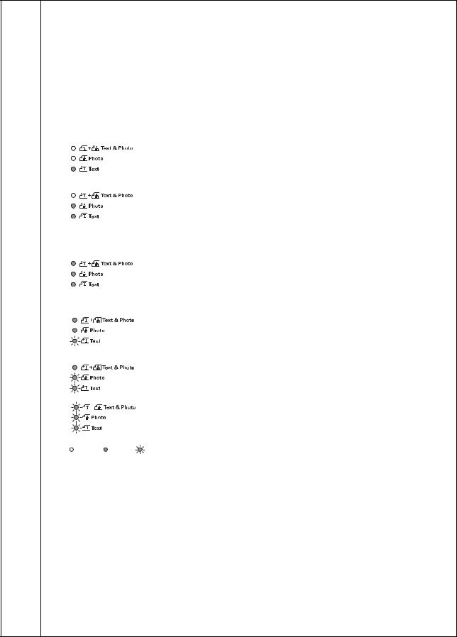
2.Select the item to be displayed using the image mode selection key and exposure adjustment keys.
Image mode LEDs |
|
Exposure |
Copy quantity display |
|
|
indicator |
|||
|
|
|
|
|
|
|
|
|
|
|
|
|
Exp. 1 (lit) |
“A” Part Code: Main PWB |
|
|
|
Exp. 2 (lit) |
Change history of the main PWB |
|
|
|
Exp. 3 (lit) |
Number of the main ROM |
|
|
|
Exp. 4 (lit) |
Number of the main ROM sub |
|
|
|
|
|
|
|
|
Exp. 1 (lit) |
“E” Part Code: Engine PWB |
|
|
|
Exp. 2 (lit) |
Change history of the engine PWB |
|
|
|
Exp. 3 (lit) |
Number of the engine ROM |
|
|
|
Exp. 4 (lit) |
Number of the engine ROM sub |
|
|
|
Exp. 5 (lit) |
Change history of the engine PWB BOOT |
|
|
|
Exp. 1 (flashing) |
Number of the engine PWB BOOT |
|
|
|
|
|
|
|
|
Exp. 1 (lit) |
“L” Part Code: Language |
|
|
|
Exp. 2 (lit) |
Change history of the standard language |
|
|
|
Exp. 3 (lit) |
Number of the standard language ROM |
|
|
|
Exp. 4 (lit) |
Change history of the optional language |
|
|
|
Exp. 5 (lit) |
Number of the optional language ROM |
|
|
|
|
|
|
|
|
Exp. 1 (lit) |
“C” Part Code: Cassette |
|
|
|
Exp. 2 (lit) |
Number of the optional first paper feeder ROM |
|
|
|
Exp. 3 (lit) |
Number of the optional second paper feeder ROM |
|
|
|
Exp. 4 (lit) |
Number of the optional third paper feeder ROM |
|
|
|
|
|
|
|
|
Exp. 1 (lit) |
“d” Part Code: DP |
|
|
|
Exp. 2 (lit) |
Number of the DP ROM |
|
|
|
|
|
|
|
|
Exp. 1 (lit) |
“P” Part Code: Printer |
|
|
|
Exp. 2 (lit) |
Change history of the optional printer |
|
|
|
Exp. 3 (lit) |
Number of the optional printer ROM |
|
|
|
|
|
: Off, |
: On, |
: Flashing |
|
|
When the optional equipment is not installed, [non] is displayed.
Completion
Press the stop/clear key. The screen for selecting a maintenance item No. is displayed.
1-3-3

3MX
Maintenance |
|
Description |
|
|
||
item No. |
|
|
|
|||
|
|
|
|
|
||
|
|
|
|
|
|
|
U068 Adjusting the scanning position for originals from the DP |
|
|
||||
Description |
|
|
|
|
|
|
Adjusts the position for scanning originals from the DP. |
|
|
||||
Purpose |
|
|
|
|
|
|
Used when the image fogging occurs because the scanning position is not proper when the DP is used. Run |
||||||
U071 to adjust the timing of DP leading edge when the scanning position is changed. |
||||||
Setting |
|
|
|
|
|
|
1. Press the start key. |
|
|
|
|
|
|
2. Change the setting using the zoom +/- keys. |
|
|
||||
|
|
|
|
|
|
|
|
Description |
Setting range |
|
Initial setting |
Change in value per step |
|
|
|
|
|
|
|
|
|
Scanning position |
-17 to 17 |
|
0 |
0.17 mm |
|
|
|
|
|
|
|
|
|
Increasing the value moves the image backward, and decreasing it moves the image forward. |
|||||
Supplement
While this maintenance item is being executed, copying from an original is available in interrupt copying mode (which is activated by pressing the interrupt key).
Completion
Press the stop/clear key. The screen for selecting a maintenance item No. is displayed.
1-3-4
3MX
Maintenance |
Description |
|
|
|
|
||
item No. |
|
|
|
|
|||
|
|
|
|
|
|||
|
|
|
|
|
|
|
|
U070 Adjusting the DP magnification |
|
|
|
|
|||
Description |
|
|
|
|
|
||
Adjusts the DP original scanning speed. |
|
|
|
|
|||
Purpose |
|
|
|
|
|
||
Make the adjustment if the magnification is incorrect in the auxiliary scanning direction when the optional DP |
|||||||
is used. |
|
|
|
|
|
||
Adjustment |
|
|
|
|
|
||
1. Press the start key. |
|
|
|
|
|
||
2. Select the item using the exposure adjustment keys. |
|
|
|
|
|||
|
|
|
|
|
|
|
|
|
Display |
|
Description |
Setting |
Initial |
Change in |
|
|
|
|
|
range |
setting |
value per step |
|
|
|
|
|
|
|
|
|
|
Exp. 1 |
|
Magnification in the auxiliary scan- |
-25 to 25 |
0 |
0.2 mm |
|
|
|
|
ning direction (first page) |
|
|
|
|
|
Exp. 2 |
|
Magnification in the auxiliary scan- |
-25 to 25 |
0 |
0.2 mm |
|
|
|
|
ning direction (second page) |
|
|
|
|
|
|
|
|
|
|
|
|
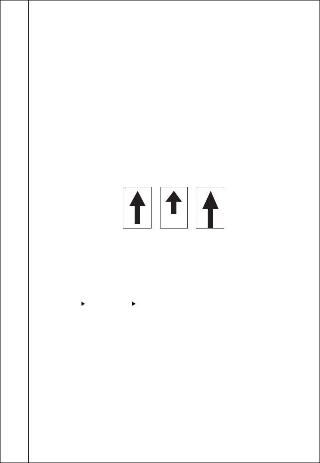
3.Press the interrupt key.
4.Place an original on the DP and press the start key to make a test copy.
5.Change the setting value using the zoom +/- keys. For copy example 1, increase the value.
For copy example 2, decrease the value.
Original |
Copy |
Copy |
|
example 1 |
example 2 |
6. Press the start key. The value is set. |
Figure 1-3-1 |
|
|
|
Caution
Check the copy image after the adjustment. If the image is still incorrect, perform the following adjustments in maintenance mode.
U070 |
|
|
U071 |
|
|
U404 |
|
|
|
(P.1-3-6) |
|
|
(P.1-3-13) |
Completion
Press the stop/clear key. The screen for selecting a maintenance item No. is displayed.
1-3-5
3MX
Maintenance |
Description |
|
|
|
|
|||
item No. |
|
|
|
|
||||
|
|
|
|
|
|
|||
|
|
|
|
|
|
|
|
|
U071 Adjusting the DP scanning timing |
|
|
|
|
||||
Description |
|
|
|
|
|
|
||
Adjusts the DP original scanning timing. |
|
|
|
|
||||
Purpose |
|
|
|
|
|
|
||
Make the adjustment if there is a regular error between the leading or trailing edges of the original and the |
||||||||
copy image when the optional DP is used. |
|
|
|
|
||||
Method |
|
|
|
|
|
|
||
1. Press the start key. |
|
|
|
|
|
|
||
2. Select the item using the exposure adjustment keys. |
|
|
|
|
||||
|
|
|
|
|
|
|
|
|
|
Exposure |
|
Description |
|
Setting |
Initial |
Change in |
|
|
indicator |
|
|
|
range |
setting |
value per step |
|
|
|
|
|
|
|
|
|
|
|
Exp. 1 |
|
DP leading edge registration |
|
-32 to 32 |
0 |
0.2 mm |
|
|
|
|
(first side) |
|
|
|
|
|
|
Exp. 2 |
|
DP trailing edge registration |
|
-42 to 32 |
0 |
0.2 mm |
|
|
|
|
(first side) |
|
|
|
|
|
|
Exp. 3 |
|
DP leading edge registration |
|
-32 to 32 |
0 |
0.2 mm |
|
|
|
|
(second side) |
|
|
|
|
|
|
Exp. 4 |
|
DP trailing edge registration |
|
-42 to 32 |
0 |
0.2 mm |
|
|
|
|
(second side) |
|
|
|
|
|
|
|
|
|
|
|
|
|
|
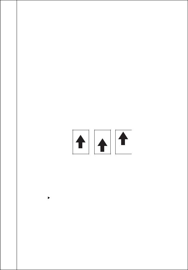
3.Press the interrupt key.
4.Place an original on the DP and press the start key to make a test copy.
5.Change the setting value using the zoom +/- keys. For copy example 1, decrease the value of exp.1. For copy example 2, increase the value of exp.1.
Original |
Copy |
Copy |
|
example 1 |
example 2 |
6. Press the start key. The value is set. |
Figure 1-3-2 |
|
|
|
Caution
Check the copy image after the adjustment. If the image is still incorrect, perform the following adjustments in maintenance mode.
U071 |
|
|
U404 |
|
|
|
(P.1-3-13) |
Completion
Press the stop/clear key. The screen for selecting a maintenance item No. is displayed.
1-3-6
3MX
Maintenance |
|
|
|
|
Description |
|
|
|
|
|
||
item No. |
|
|
|
|
|
|
|
|
|
|||
|
|
|
|
|
|
|
|
|
|
|
|
|
|
|
|
|
|
|
|
|
|
|
|
|
|
U072 Adjusting the DP center line |
|
|
|
|
|
|||||||
Description |
|
|
|
|
|
|
|
|
|
|
||
Adjusts the scanning start position for the DP original. |
|
|
|
|
|
|||||||
Purpose |
|
|
|
|
|
|
|
|
|
|
||
Make the adjustment if there is a regular error between the centers of the original and the copy image when |
||||||||||||
the optional DP is used. |
|
|
|
|
|
|
|
|
|
|
||
Adjustment |
|
|
|
|
|
|
|
|
|
|
||
1. |
Press the start key. |
|
|
|
|
|
|
|
|
|
|
|
2. |
Select the item using the exposure adjustment keys. |
|
|
|
|
|
||||||
|
|
|
|
|
|
|
|
|
|
|
|
|
|
Exposure |
|
Description |
|
Setting |
Initial |
Change in |
|
||||
|
indicator |
|
|
range |
setting |
value per step |
|
|||||
|
|
|
|
|
|
|
|
|||||
|
|
|
|
|
|
|
|
|
|
|
|
|
|
Exp. 1 |
|
DP center line (first side) |
|
-6.6 to 6.6 |
0 |
0.15 mm |
|
||||
|
Exp. 2 |
|
DP center line (second side) |
|
-3.0 to 3.0 |
0 |
0.15 mm |
|
||||
|
|
|
|
|
|
|
|
|
|
|
|
|
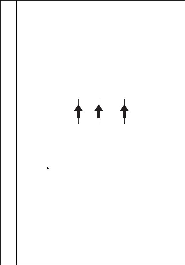
3. |
Press the interrupt key. |
|
|
|
|
|
||||||
4. |
Place an original on the DP and press the start key to make a test copy. |
|
|
|||||||||
5. |
Change the setting value using the zoom +/- keys. |
|
|
|
|
|
||||||
|
For copy example 1, increase the value. |
|
|
|
|
|
||||||
|
For copy example 2, decrease the value. |
|
|
|
|
|
||||||
|
|
|
|
|
|
|
|
|
|
|
|
|
|
|
|
|
|
|
|
|
|
|
|
|
|
Original |
Copy |
Copy |
|
example 1 |
example 2 |
6. Press the start key. The value is set. |
Figure 1-3-3 |
|
|
|
Caution
Check the copy image after the adjustment. If the image is still incorrect, perform the following adjustments in maintenance mode.
U072 |
|
|
U404 |
|
|
|
(P.1-3-13) |
Completion
Press the stop/clear key. The screen for selecting a maintenance item No. is displayed.
1-3-7

3MX
Maintenance |
Description |
|
|
|||
item No. |
|
|
||||
|
|
|
|
|
||
|
|
|
|
|
|
|
U074 Adjusting the DP input light luminosity |
|
|
|
|
|
|
Description |
|
|
|
|
|
|
Adjusts the luminosity of the exposure lamp for scanning originals from the DP. |
|
|
||||
Purpose |
|
|
|
|
|
|
Used if the exposure amount differs significantly between when scanning an original on the platen and when |
||||||
scanning an original from the DP. |
|
|
|
|
|
|
Setting |
|
|
|
|
|
|
1. Press the start key. |
|
|
|
|
|
|
2. Change the setting using the zoom +/- keys. |
|
|
||||
|
|
|
|
|
|
|
|
Description |
|
Setting range |
|
Initial setting |
|
|
|
|
|
|
|
|
|
DP input light luminosity |
|
0 to 8 |
|
1 |
|
|
|
|
|
|
||
|
Increasing the setting makes the luminosity higher, and decreasing it makes the luminosity lower. |
|||||
3. Press the start key. The value is set. |
|
|
|
|
|
|
Supplement
While this maintenance item is being executed, copying from an original is available in interrupt copying mode (which is activated by pressing the interrupt key).
Completion
Press the stop/clear key. The screen for selecting a maintenance item No. is displayed.
1-3-8
3MX
Maintenance |
Description |
|||||
item No. |
||||||
|
|
|
|
|
||
|
|
|
|
|
|
|
U076 Adjusting the DP automatically |
|
|
|
|
|
|
Description |
|
|
|
|
|
|
Uses a specified original and automatically adjusts the following items in the DP scanning section. |
||||||
Adjusting the DP magnification (U070) |
|
|
|
|
|
|
Adjusting the DP scanning timing (U071) |
|
|
|
|
|
|
Adjusting the DP center line (U072) |
|
|
|
|
|
|
When you run this maintenance mode, the preset values of U070, U071 and U072 will also be updated. |
||||||
Purpose |
|
|
|
|
|
|
To perform automatic adjustment of various items in the DP scanning section. |
||||||
Method |
|
|
|
|
|
|
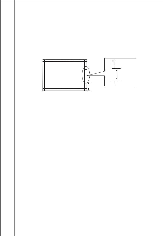
1. Set a specified original (P/N: 302AC68243) in the DP. |
||||||
Cut the trailing edge of the original. |
|
|
|
|
|
|
|
|
|
|
5 mm |
||
F |
|
|
|
|
149 ± 1 mm |
|
|
|
|
|
|
||
|
|
|
|
|
||
R |
|
|
|
|
|
|
|
|
|
|
|
||
|
|
|
|
|
||
|
74 ± 1 mm |
|||||
|
Figure 1-3-4 |
|||||
2.Press the start key. "on" appears.
3.Press the start key. Auto adjustment starts. When adjustment is complete, "Gd" appears.
4.Display each setting value after adjustment using the exposure adjustment keys.
Exposure indicator |
Description |
|
|
Exp. 1 |
Execution result |
Exp. 2 |
DP scanning timing |
Exp. 3 |
DP center line |
Exp. 4 |
DP magnification |
|
|
If a problem occurs during auto adjustment, "nG" is displayed and operation stops. Determine the details of the problem and either repeat the procedure from the beginning, or adjust the remaining items manually by running the corresponding maintenance items.
Completion
Press the stop/clear key after auto adjustment is complete.The screen for selecting a maintenance item No. is displayed.
If the stop/clear key is pressed during auto adjustment, adjustment stops and no settings are changed.
1-3-9
 Loading...