


Part Number 910568-001

IMPORTANT SAFETY & INSTALLATION INSTRUCTIONS
INSTRUCTIONS PERTAINING TO THE RISK OF FIRE ELECTRIC SHOCK , OR INJURY TO PERSONS
WARNING: When using electric products, basic precautions should always be followed, including the following:
1. Read all the Safety and Installation Instructions and Explanation of Graphic Symbols before using the product.
2. This product must be grounded. If it should malfunction or break down, grounding provides a path of least resistance for electric current to reduce the risk of electric shock. This product is equipped with a power supply cord having an equipment-grounding conductor and a grounding plug. The plug must be plugged into an appropriate outlet which is properly installed and grounded in accordance with all local codes and ordinances.
DANGER: Improper connection of the equipment-grounding conductor can result in a risk of electric shock. Do not modify the plug provided with the product – if it will not fit the outlet, have a proper outlet installed by a qualified electrician. Do not use an adaptor which defeats the function of the equipment-grounding conductor. If you are in doubt as to whether the product is properly grounded, check with a qualified serviceman or electrician.
3. Do not use this product near water – for example, near a bathtub, washbowl, kitchen sink, in a wet basement, or near a swimming pool, or the like.
4. This product should only be used with a stand or cart that is recommended by the manufacturer.
5. This product, either alone or in combination with an amplifier and speakers or headphones, may be capable of producing sound levels that could cause permanent hearing loss. Do not operate for a long period of time at a high volume level or a level that is uncomfortable. If you experience any hearing loss or ringing in the ears, you should consult an audiologist.
6. This product should be located so that its location or position does not interfere with its proper ventilation.
7. The product should be located away from heat sources such as radiators, heat registers, or other products that produce heat.
8. The product should be connected to a power supply only of the type described in the operating instructions or as marked on the product.
9. This product may be equipped with a polarized line plug (one blade wider than the other). This is a safety feature. If you are unable to insert the plug into the outlet, contact an electrician to replace your obsolete outlet. Do not defeat the safety purpose of the plug.
10. The power supply cord of the product should be unplugged from the outlet when left unused for a long period of time. When unplugging the power supply cord, do not pull on the cord, but grasp it by the plug.
11. Care should be taken so that objects do not fall and liquids are not spilled into the enclosure through openings.
12. The product should be serviced by qualified service personnel when:
A. The power supply cord or the plug has been damaged;
B. Objects have fallen, or liquid has been spilled into the product; C. The product has been exposed to rain;
D. The product does not appear to be operating normally or exhibits a marked change in performance; E. The product has been dropped, or the enclosure damaged.
13. Do not attempt to service the product beyond that described in the user maintenance instructions. All other servicing should be referred to qualified service personnel.
14. WARNING: Do not place objects on the product’s power supply cord, or place the product in a position where anyone could trip over, walk on, or roll anything over cords of any type. Do not allow the product to rest on or be installed over cords of any type. Improper installations of this type create the possibility of a fire hazard and/or personal injury.
RADIO AND TELEVISION INTERFERENCE
WARNING: Changes or modifications to the instrument not expressly approved by Young Chang could void your authority to operate the instrument.
IMPORTANT: When connecting this product to accessories and/or other equipment use only high quality shielded cables.
NOTE: This instrument has been tested and found to comply with the limits for a Class B digital device, pursuant to Part 15 of the FCC Rules. These limits are designed to provide reasonable protection against harmful interference in a residential installation. This instrument generates, uses, and can radiate radio frequency energy and, if not installed and used in accordance with the instructions, may cause harmful interference to radio communications. However, there is no guarantee that interference will not occur in a particular installation. If this instrument does cause harmful interference to radio or television reception, which can be determined by turning the instrument off and on, the user is encouraged to try to correct the interference by one or more of the following measures:
•Reorient or relocate the receiving antenna.
•Increase the separation between the instrument and the receiver.
•Connect the instrument into an outlet on a circuit other than the one to which the receiver is connected.
•If necessary consult your dealer or an experienced radio/television technician for additional suggestions.
NOTICE
This apparatus does not exceed the Class B limits for radio noise emissions from digital apparatus set out in the Radio Interference Regulations of the Canadian Department of Communications.
AVIS
Le present appareil numerique n’emet pas de bruits radioelectriques depassant les limites applicables aux appareils numeriques de la class B prescrites dans le Reglement sur le brouillage radioelectrique edicte par le ministere des Communications du Canada.
SAVE THESE INSTRUCTIONS
ii
CAUTION
RISK OF ELECTRIC SHOCK
DO NOT OPEN
CAUTION: TO REDUCE THE RISK OF ELECTRIC SHOCK,
DO NOT REMOVE THE COVER.
NO USER SERVICEABLE PARTS INSIDE.
REFER SERVICING TO QUALIFIED SERVICE PERSONNEL.
The lightning flash with the arrowhead symbol, within an equilateral triangle is intended to alert the user to the presence of uninsulated "dangerous voltage" within the product's enclosure that may be of sufficient magnitude to constitute a risk of electric shock to persons.
The exclamation point within an equilateral triangle is intended to alert the user to the presence of important operating and maintenance (servicing) instructions in the literature accompanying the product.
SAFETY INSTRUCTIONS
1)Read these instructions.
2)Keep these instructions.
3)Heed all warnings.
4)Follow all instructions.
5)Do not use this apparatus near water.
6)Clean only with dry cloth.
7)Do not block any of the ventilation openings. Install in accordance with the manufacturer’s instructions.
8)Do not install near any heat sources such as radiators, heat registers, stoves, or other apparatus (including amplifiers) that produce heat.
9)Do not defeat the safety purpose of the polarized or grounding-type plug. A polarized plug has two blades with one wider than the other. A grounding type plug has two blades and a third grounding prong. The wide blade or the third prong are provided for your safety. If the provided plug does not fit into your outlet, consult an electrician for replacement of the obsolete outlet.
10)Protect the power cord from being walked on or pinched, particularly at plugs, convenience receptacles, and the point where they exit from the apparatus.
11)Only use attachments/accessories specified by the manufacturer.
12) Use only with a cart, stand, tripod, bracket, or table specified by the manufacturer, or sold with the apparatus. When a cart is used, use caution when moving the cart/ apparatus combination to avoid injury from tip-over.
13) Unplug this apparatus during lightning storms or when unused for long periods of time.
14)Refer all servicing to qualified service personnel. Servicing is required when the apparatus has been damaged in any way, such as power-supply cord or plug is damaged, liquid has been spilled or objects have fallen into the apparatus, the apparatus has been exposed to rain or moisture, does not operate normally, or has been dropped.
Warning: To reduce the risk of fire or electric shock, do not expose this apparatus to rain or moisture. Do not expose this equipment to dripping or splashing and ensure that no objects filled with liquids, such as vases, are placed on the equipment.
To completely disconnect this equipment from the AC Mains, disconnect the power supply cord plug from the AC receptacle.
©2014 Young Chang Co., Ltd. All rights reserved. Kurzweil® is a product line of Young Chang Co., Ltd. Kurzweil®, Young Chang®, V. A. S. T.®, and PC3A™ are trademarks of Young Chang Co., Ltd. All other trademarks and copyrights are property of their respective companies. Product features and specifications are subject to change without notice.
You may legally print up to two (2) copies of this document for personal use. Commercial use of any copies of this document is prohibited. Young Chang Co. retains ownership of all intellectual property represented by this document.
iii

Kurzweil International Contacts
Contact the Kurzweil office listed below to locate your local Kurzweil representative.
US Customers: |
Customers outside the US: |
American Music & Sound |
Young Chang Co., LTD. |
22020 Clarendon Street, Suite 305 |
9th Floor, Bldg 102, I-Park, |
Woodland Hills, CA 91367 |
Jeongja-Dong, Bundang-Gu, Seongnam-Si, |
|
Gyeonggi-Do |
Tel: 800-431-2609 |
463-859 South Korea |
Fax: 818-597-0411 |
Tel: +82 31 786 7900 |
Email: info@americanmusicandsound.com |
www.kurzweil.com
support@kurzweil.com
www.facebook.com/kurzweilmusicsystems/
www.twitter.com/KurzweilMusic
www.youtube.com/user/KurzweilTutorials
iv

Table of Contents
Kurzweil International Contacts iv
Chapter 1 Introduction
Keeping Current |
1-2 |
Overview of the PC3A |
1-2 |
VAST Synthesis |
1-3 |
KB3 Tone Wheel Emulation |
1-3 |
VA-1 Programs |
1-3 |
How to Use This Manual |
1-4 |
Do I Have Everything? |
1-4 |
Boot Loader |
1-4 |
Battery |
1-4 |
Options |
1-5 |
Sound ROM Expansion Card |
1-5 |
Pedals |
1-5 |
Ribbon Controller |
1-5 |
Breath Controller |
1-5 |
USB Storage Device |
1-5 |
Chapter 2 Startup
Make Connections |
2-1 |
Make Music |
2-1 |
Startup—the Details |
2-2 |
Before You Start... |
2-2 |
Connecting the Power Cable (Line Cord) |
2-2 |
Connecting Audio Cables |
2-2 |
Connecting MIDI |
2-3 |
Pedals |
2-4 |
Breath |
2-4 |
Ribbon |
2-5 |
Switching On the Power |
2-5 |
USB Storage Port |
2-6 |
USB Computer Port |
2-6 |
Setting the Clock |
2-7 |
PC3A Programs |
2-7 |
Selecting Programs |
2-7 |
Easy Audition |
2-7 |
Program Mode Display |
2-8 |
VAST Programs |
2-8 |
KB3 Programs |
2-9 |
Setups |
2-9 |
Quick Access |
2-9 |
The Other Modes |
2-10 |
Software Upgrades |
2-10 |
i

Chapter 3 User Interface Basics
Mode Selection |
3-1 |
Mode Buttons |
3-2 |
Bank Buttons |
3-2 |
Sliders |
3-3 |
Program and Category Buttons |
3-4 |
Picking favorites |
3-4 |
Pitch Wheel and Mod Wheel |
3-5 |
Navigation |
3-6 |
The Display |
3-6 |
Pages |
3-6 |
The Top Line |
3-6 |
The Bottom Line |
3-6 |
The Soft Buttons |
3-7 |
The Cursor Buttons |
3-7 |
The Chan/Layer Buttons |
3-7 |
The Edit Button |
3-8 |
The Exit Button |
3-8 |
Data Entry |
3-9 |
The Alpha Wheel |
3-9 |
The Plus/Minus Buttons |
3-9 |
The Alphanumeric Pad |
3-9 |
Double Button Presses |
3-10 |
Intuitive Data Entry |
3-11 |
Changing the Current Layer in Multi-Layer Programs |
3-11 |
Search |
3-12 |
Quick Song Recording and Playback |
3-12 |
Chapter 4 The Operating Modes
What the Modes Are |
4-1 |
Selecting Modes |
4-1 |
Finding Square One |
4-2 |
Using the Modes |
4-2 |
Program Mode |
4-2 |
Setup Mode |
4-2 |
Quick Access Mode |
4-3 |
EffectsMode |
4-3 |
MIDI Mode |
4-3 |
Master Mode |
4-3 |
Song Mode |
4-3 |
Storage Mode |
4-3 |
Chapter 5 Editing Conventions
Introduction to Editing |
5-1 |
What’s an Object? |
5-1 |
Object Type and ID |
5-2 |
Saving and Naming |
5-3 |
ROM Objects |
5-4 |
Memory Objects |
5-4 |
Keyboard Naming |
5-5 |
ii

Deleting Objects |
5-6 |
Dependent Objects |
5-6 |
Saving and Loading Files—Storage Mode |
5-6 |
Special Button Functions |
5-7 |
Chapter 6 Program Mode
The Program Mode Page |
6-1 |
Selecting Programs |
6-1 |
The Soft Buttons in Program Mode |
6-2 |
The Info Box |
6-2 |
Controllers Assignments For Factory ROM Programs |
6-2 |
Saving Controller Settings in Program Mode |
6-3 |
The Arpeggiator In Program Mode |
6-3 |
MIDI Channels |
6-3 |
VAST and KB3 Programs |
6-4 |
VAST Program Structure |
6-4 |
KB3 Program Structure |
6-6 |
KB3 Mode |
6-6 |
KB3EffectsAndReal-timeControls |
6-6 |
MIDI Control of KB3 Programs |
6-8 |
Control Setup |
6-9 |
Control Setup Overview |
6-9 |
Control Setup Advanced Features |
6-10 |
Selecting And Editing The Control Setup |
6-10 |
Editing VAST Programs |
6-12 |
The Soft Buttons in the Program Editor |
6-12 |
The MODE Buttons in the Program Editor |
6-13 |
Assigning Program Parameters to Control Sources |
6-13 |
The KEYMAP Page |
6-14 |
Keymap |
6-14 |
Transpose (Xpose) |
6-14 |
Key Tracking (KeyTrk) |
6-14 |
Velocity Tracking (VelTrk) |
6-15 |
Method (AltMethod) |
6-15 |
Stereo |
6-15 |
Timbre Shift |
6-16 |
Playback Mode |
6-16 |
Alternative Controller (AltControl) |
6-16 |
Alternative Switch (AltControl and AltMethod) |
6-16 |
The LAYER Page |
6-17 |
Low Key (LoKey) |
6-18 |
High Key (HiKey) |
6-18 |
Low Velocity (LoVel) |
6-18 |
High Velocity (HiVel) |
6-18 |
Pitch Bend Mode (Bend) |
6-18 |
Trigger (Trig) |
6-18 |
Delay Control (DlyCtl) |
6-18 |
Minimum Delay (MinDly), Maximum Delay (MaxDly) |
6-18 |
Enable |
6-19 |
Enable Sense (S) |
6-19 |
iii

Opaque |
6-20 |
Sustain Pedal (SusPdl) |
6-20 |
Sostenuto Pedal (SosPdl) |
6-20 |
Freeze Pedal (FrzPdl) |
6-20 |
Ignore Release (IgnRel) |
6-20 |
Hold Through Attack (ThrAtt) |
6-20 |
Hold Until Decay (TilDec) |
6-21 |
The PITCH Page |
6-21 |
The AMP Page |
6-21 |
The Algorithm (ALG) Page |
6-22 |
Algorithm Basics |
6-23 |
Common DSP Control Parameters |
6-24 |
Alt Input for Algorithms (Cascade Mode) |
6-27 |
Dynamic VAST |
6-28 |
The DSP Control (DSPCTL) Page |
6-29 |
The DSP Modulation (DSPMOD) Page |
6-30 |
The OUTPUT Page |
6-31 |
Pan |
6-32 |
Pan Mode |
6-32 |
Output: Pan, Gain, and Mode |
6-33 |
Pan Table |
6-33 |
Crossfade and Crossfade Sense (XFadeSense) |
6-33 |
Drum Remap |
6-33 |
Exclusive Zone Map |
6-34 |
The COMMON Page |
6-35 |
Pitch Bend Range Up and Down |
6-35 |
Monophonic |
6-35 |
Legato Play |
6-36 |
Portamento |
6-36 |
Portamento Rate |
6-36 |
Attack Portamento |
6-36 |
Mono Sample XFade |
6-37 |
Globals |
6-37 |
Output: Gain, Pan, and Pan Mode |
6-37 |
Demo Song |
6-37 |
The LFO Page |
6-38 |
Minimum Rate |
6-39 |
Maximum Rate |
6-39 |
Rate Control |
6-39 |
LFO Shape |
6-39 |
LFO Phase |
6-39 |
The ASR Page |
6-40 |
Trigger |
6-40 |
Mode |
6-40 |
Delay |
6-40 |
Attack |
6-41 |
Release |
6-41 |
The Function (FUN) Page |
6-41 |
The Amplitude Envelope (AMPENV) Page |
6-42 |
Attack Segment Times |
6-43 |
iv

Attack Segment Levels |
6-43 |
Decay Segment |
6-43 |
Release Segments |
6-43 |
Loop Type |
6-44 |
Number of Loops |
6-44 |
The Envelope 2 (ENV2) and Envelope 3 (ENV3) Pages |
6-44 |
The Envelope Control (ENVCTL) Page |
6-45 |
Adjust |
6-46 |
Key Tracking |
6-46 |
Velocity Tracking |
6-46 |
Source, Depth |
6-46 |
Impact |
6-47 |
The Program FX (PROGFX) Page |
6-47 |
Insert |
6-48 |
Aux 1, Aux 2 |
6-48 |
Output |
6-48 |
Auxiliary Send Parameters |
6-48 |
Aux1 Mod, Aux2 Mod |
6-49 |
The Layer FX (LYR_FX) Page |
6-49 |
The Controllers (CTLS) Page |
6-50 |
INFO |
6-51 |
Function Soft Buttons |
6-51 |
Set Controllers (SetCtl) |
6-52 |
New Layer (NewLyr) |
6-52 |
Duplicate Layer (DupLyr) |
6-52 |
Import Layer (ImpLyr) |
6-52 |
Delete Layer (DelLyr) |
6-52 |
Name, Save, Delete |
6-52 |
Editing VAST Programs With KVA Oscillators |
6-53 |
Basic Use of KVA Oscillators |
6-53 |
Setting KVA Oscillator Type |
6-54 |
Advanced Use Of KVA Oscillators |
6-55 |
Editing KB3 Programs |
6-59 |
KB3 Editor: The Tone Wheels (TONEWL) Page |
6-59 |
Upper Tone Wheel Keymap |
6-59 |
Upper Volume Adjust |
6-60 |
Number of Tone Wheels |
6-60 |
Organ Map |
6-60 |
Wheel Volume Map |
6-60 |
Globals |
6-60 |
Lower Transpose / Upper Transpose |
6-60 |
KB3 Editor: The Drawbars (DRAWBR) Page |
6-61 |
Mode |
6-61 |
Steps |
6-61 |
Volume |
6-61 |
Tune |
6-61 |
KB3 Editor: The Set Drawbars (SetDBR) Soft Button |
6-62 |
KB3 Editor: The PITCH Page |
6-62 |
KB3 Editor: The AMP Page |
6-62 |
KB3 Editor: The PERC1 Page |
6-63 |
v

Percussion |
6-63 |
Volume |
6-63 |
Decay |
6-63 |
Harmonic |
6-64 |
VelTrack |
6-64 |
LowHarm |
6-64 |
HighHarm |
6-64 |
StealBar |
6-64 |
KB3 Editor: The PERC2 Page |
6-64 |
PercLevel, DecayTime, OrgLevel |
6-64 |
KB3 Editor: The KEYCLK Page |
6-65 |
KeyClick |
6-65 |
Volume |
6-65 |
Decay |
6-65 |
VelTrk |
6-65 |
Pitch |
6-66 |
Random |
6-66 |
ReTrigThresh |
6-66 |
Note Attack |
6-66 |
Note Release |
6-66 |
KB3 Editor: The MISC Page |
6-67 |
PreampResp |
6-67 |
Leakage |
6-67 |
LeakMode |
6-68 |
SpeedCtl |
6-68 |
VibChorCtl |
6-68 |
VibChorSel |
6-68 |
VolAdjust |
6-68 |
BendRngUp, BendRngDn |
6-68 |
Sustain |
6-68 |
Sostenuto |
6-68 |
LesliePedal |
6-68 |
KB3 Editor: The EQ Page |
6-69 |
KB3 Editor: The OUTPUT Page |
6-70 |
Exp Pedal |
6-70 |
KB3 Editor: The Program FX (PROGFX) Page |
6-70 |
KB3 Editor: The LFO, ASR, and FUN Pages |
6-70 |
KB3 Programming Tips |
6-71 |
Chapter 7 Setup Mode
Zone-status LEDs in Setup Mode |
7-2 |
Soloing a Zone |
7-3 |
The Setup Editor |
7-3 |
The Channel/Program (CH/PROG) Page |
7-4 |
Program |
7-4 |
Destination |
7-5 |
Channel |
7-5 |
MidiBank |
7-5 |
MIDI Program (MidiProg) |
7-6 |
Status |
7-6 |
vi
Out |
7-6 |
Input Channel |
7-6 |
MIDI Bank Mode (BankMode) |
7-7 |
Entry Program Change (EntryProgChg) |
7-8 |
Arpeggiator |
7-8 |
The Key/Velocity (KEY-VEL) Page |
7-9 |
Low Key (LoKey), High Key (HiKey) |
7-10 |
Transpose |
7-10 |
Note Map |
7-10 |
Velocity Scale (VelScale) |
7-11 |
VelocityOffset |
7-12 |
Velocity Curve (VelCurve) |
7-14 |
Low Velocity (LoVel), HighVelocity (HiVel) |
7-16 |
The Pan/Volume (PAN/VOL) Page |
7-17 |
Entry Volume, Exit Volume |
7-17 |
Entry Pan, Exit Pan |
7-17 |
The BEND Page |
7-18 |
Bend Range (Semitones) and Bend Range (Cents): Up and Down |
7-18 |
Aux Bend 1 Up and Aux Bend 1 Down |
7-19 |
Aux Bend 2 Range |
7-19 |
Controllers |
7-19 |
Continuous Controllers |
7-20 |
Switch Controllers |
7-21 |
The Controller Destination List |
7-21 |
Shift Key Number, Shift Key (ShKeyNum, ShiftKey) |
7-26 |
Continuous Controller Parameters |
7-29 |
Switch Controller Parameters |
7-30 |
The WHEEL Page |
7-32 |
The SLIDER and SLID2 Pages |
7-33 |
The Continuous Control Pedal (CPEDAL) Page |
7-34 |
The Pressure (PRESS) Page |
7-35 |
The Footswitch Pages (FT SW1, FT SW2, FT SW3) |
7-36 |
The Arpeggiator Switch (ARP SW) Page |
7-37 |
The SWITCH Page |
7-38 |
The RIBBON Page |
7-39 |
TheRibbonConfiguration(RIBCFG)Page |
7-40 |
RibbonConfiguration |
7-40 |
Position Mode (PosMode) |
7-41 |
Spring |
7-41 |
Center |
7-41 |
The ARPEGGIATOR & ARPEGGIATOR 2 (ARP1, ARP2) Pages |
7-42 |
The ARPEGGIATOR Page |
7-42 |
The ARPEGGIATOR 2 Page |
7-49 |
|
7-49 |
Real-time Control of Arpeggiator Parameters |
7-53 |
Riffs |
7-55 |
The RIFF1 Page |
7-55 |
The RIFF2 Page |
7-58 |
Real-timeControlofRiffParameters |
7-63 |
vii

The FX Pages: FX, AUXFX1, AUXFX2, and MASTFX |
7-64 |
The Programmable Switch Pages: SWPRG1 to SWPRG8 |
7-64 |
The COMMON Page |
7-65 |
Tempo |
7-65 |
Clock Source |
7-65 |
Aux FX Channel |
7-65 |
KB3 Channel |
7-66 |
Mutes |
7-66 |
Arpeggiator Global (ArpGlobal) |
7-66 |
TRIGGER KEYS (KEYTRG) |
7-67 |
The Utility Soft Buttons |
7-68 |
Name |
7-68 |
Save |
7-68 |
Delete |
7-68 |
New Zone (NewZn) |
7-68 |
Duplicate Zone (DupZn) |
7-68 |
Import Zone (ImpZn) |
7-68 |
Delete Zone (DelZn) |
7-68 |
Recording A Setup To Song Mode |
7-69 |
Chapter 8 Quick Access Mode
Soft Buttons In Quick Access Mode |
8-2 |
The QA Editor |
8-2 |
Chapter 9 Effects and Effect Mode
EffectsOverview |
9-1 |
InsertEffects |
9-1 |
AuxEffects |
9-1 |
MasterEffects |
9-2 |
Chains |
9-2 |
Signal Flow |
9-2 |
DSPUnits-ManageandDistributeProcessorPowerforEffects |
9-3 |
Aux Override |
9-3 |
EffectModeandtheEffectsPages |
9-4 |
TheEffectsEnablePage |
9-4 |
The Aux 1 Override and Aux 2 Override Pages |
9-5 |
TheMasterEffectsPage |
9-8 |
The Chain Editor |
9-9 |
The MAIN Page |
9-9 |
The MOD Pages |
9-10 |
FXLFO, FXASR, and FXFUN pages |
9-11 |
INFO |
9-11 |
EffectsParameters |
9-12 |
General Parameters |
9-12 |
Reverbs |
9-13 |
Delays |
9-14 |
Equalizers (EQ) |
9-15 |
Compressors, Expanders, and Gates |
9-16 |
Chorus |
9-18 |
Flanger |
9-19 |
viii

Quantize |
9-19 |
LaserVerb |
9-19 |
Filters |
9-20 |
Distortion |
9-21 |
Rotating Speakers |
9-22 |
Vibrato/Chorus |
9-23 |
Tremolo and AutoPan |
9-24 |
Pitcher |
9-25 |
Ring Modulation |
9-25 |
Stereo Simulation |
9-25 |
Chapter 10 MIDI Mode
The TRANSMIT Page |
10-1 |
Control Setup |
10-2 |
Destination |
10-2 |
Channel |
10-2 |
Transpose |
10-2 |
Velocity Map (Transmit) |
10-3 |
Pressure Map (Transmit) |
10-4 |
Program Change (ProgChang) |
10-5 |
Change Setups (ChgSetups) |
10-5 |
The RECEIVE Page |
10-5 |
Basic Channel |
10-6 |
MIDI Receive Mode (MIDI Mode) |
10-6 |
AllNotesOff |
10-6 |
Program Change Mode (PrgChgMode) |
10-6 |
Velocity Map (Receive) |
10-7 |
Pressure Map (Receive) |
10-8 |
System Exclusive ID (SysExID) |
10-9 |
Bank Select |
10-9 |
Local Keyboard Channel (LocalKbdCh) |
10-10 |
The Channels Page |
10-14 |
Enable |
10-14 |
Program |
10-14 |
Pan |
10-15 |
Volume |
10-15 |
Program Lock, Pan Lock, Volume Lock |
10-15 |
Program Change Formats |
10-15 |
Extended Program Changes |
10-16 |
QAccess |
10-16 |
The Soft Buttons in MIDI Mode |
10-18 |
Program Change (PrgChg) |
10-18 |
Reset Channels (RsetCh) |
10-18 |
Panic |
10-18 |
Chapter 11 Master Mode
MAIN |
11-1 |
Tune |
11-2 |
Transpose |
11-2 |
FX Mode |
11-2 |
ix

Drum Remap |
11-2 |
ID Entry |
11-2 |
Setup Controllers (SetupCtls) |
11-2 |
Master Table Lock (Master Lock) |
11-3 |
Demo Button |
11-3 |
Buttons Mode (Buttons) |
11-3 |
Display |
11-3 |
MAPS |
11-5 |
Velocity Map (Master) |
11-5 |
Pressure Map (Master) |
11-7 |
Intonation |
11-8 |
Key Action Map |
11-9 |
Intonation Key (Int.Key) |
11-9 |
Default Sequence |
11-10 |
OUTPUT |
11-10 |
Output Clock |
11-10 |
Digital Output Volume (Dig. out volume) |
11-10 |
Digital Output (Dig. Out) |
11-10 |
Aux Out Pair Mode |
11-10 |
Clock Source |
11-11 |
TEMPO |
11-11 |
GeneralMIDIMode(GMOn,GMOff) |
11-12 |
OBJECT |
11-13 |
Rename |
11-14 |
Delete |
11-14 |
UTILS (UTILITIES) |
11-16 |
CLOCK |
11-17 |
Reset |
11-17 |
Loader |
11-18 |
About |
11-18 |
Save |
11-18 |
Preview Sample (PRVIEW) |
11-18 |
Chapter 12 Song Mode and the Song Editor
Getting Started with the Sequencer |
12-1 |
What is a Sequencer? |
12-1 |
Song Mode: The MAIN Page |
12-1 |
Current Song (CurSong) |
12-2 |
Tempo |
12-2 |
Recording Track (RecTrk) |
12-3 |
Program (Prog) |
12-3 |
Track Number (Trk:#) |
12-3 |
Volume (Vol) |
12-4 |
Pan |
12-5 |
Mode |
12-6 |
Location (Locat) |
12-6 |
Mode Indicators (+ and x): |
12-6 |
Activity Indicators |
12-6 |
Track Status Indicators |
12-6 |
Track Channels |
12-7 |
x

Soft Buttons on the MAIN Page |
12-7 |
The Save Changes Dialog |
12-8 |
Song Mode: The BIG Page |
12-10 |
Time In |
12-10 |
Time Out |
12-10 |
Song End |
12-11 |
Loop |
12-11 |
RecMode |
12-11 |
Metron |
12-11 |
Song Mode: The FX Pages |
12-12 |
Song Mode: The MIXER Page |
12-12 |
Out |
12-12 |
The Rec, Play, and Stop Soft Buttons |
12-13 |
The Keep Soft Button |
12-13 |
The Done Soft Button |
12-13 |
Song Mode: The METRONOME Page |
12-13 |
Metronome |
12-14 |
CountOff |
12-14 |
Program |
12-14 |
Channel |
12-14 |
Strong Note |
12-14 |
Strong Vel |
12-14 |
Soft Note |
12-14 |
Soft Vel |
12-14 |
The Rec, Play, and Stop Soft Buttons |
12-14 |
The Done Soft Button |
12-14 |
Song Mode: The Filter Pages (RECFLT and PLYFLT) |
12-15 |
Notes |
12-15 |
LoKey |
12-15 |
Hi |
12-15 |
LoVel |
12-16 |
Hi |
12-16 |
Controllers |
12-16 |
Controller |
12-16 |
LoVal |
12-16 |
Hi |
12-16 |
PitchBend |
12-16 |
ProgChange |
12-16 |
MonoPress |
12-16 |
PolyPress |
12-16 |
The Rec, Play, and Stop Soft Buttons |
12-16 |
The Done Soft Button |
12-16 |
Song Mode: The MISC Page |
12-17 |
Control Chase |
12-17 |
Quant |
12-17 |
Grid |
12-17 |
Swing |
12-18 |
Release |
12-18 |
Key Wait |
12-18 |
Song Mode: The STATS Page |
12-18 |
xi

The Song Editor |
12-19 |
Song Editor: The COMMON Page |
12-19 |
Tempo |
12-19 |
TimeSig |
12-19 |
FX Track |
12-20 |
DrumTrack |
12-20 |
MidiDst |
12-20 |
Soft Buttons on the COMMON Page |
12-21 |
Song Editor: The TRACK Page |
12-21 |
Common Parameters for Edit Song: Track Functions |
12-22 |
Region/Criteria Box Parameters |
12-22 |
Soft Buttons on the TRACK Page |
12-23 |
Song Editor: Track Functions |
12-24 |
Erase |
12-24 |
Copy |
12-24 |
Bounce |
12-25 |
Insert |
12-26 |
Delete |
12-26 |
Quantize |
12-27 |
Shift |
12-28 |
Transpose |
12-28 |
Grab |
12-29 |
Change |
12-30 |
Remap |
12-31 |
Song Editor: The EVENT Page |
12-31 |
Initial Program, Volume, Pan |
12-32 |
Location |
12-32 |
Bar, Beat, and Tick |
12-32 |
Event Type and Value |
12-32 |
Soft Buttons on the EVENT Page |
12-33 |
Tempo Track |
12-33 |
Chapter 13 Storage Mode
Storage Mode Page |
13-1 |
Using USB Devices |
13-2 |
Storage Mode Common Features |
13-4 |
Directories |
13-4 |
Path |
13-4 |
Common Dialogues |
13-4 |
The STORE Page |
13-6 |
Storing Overview |
13-6 |
Select Object Type To Store |
13-7 |
Select Object Range To Store |
13-7 |
The Store Advanced Page |
13-7 |
The LOAD Page |
13-9 |
Loading Individual Objects From a .P3A Or Compatible File Type |
13-10 |
Loading Methods |
13-11 |
The Utilities (UTILS) Page |
13-14 |
Soft Buttons on the Utilities Page |
13-14 |
Export |
13-15 |
xii

Format |
13-15 |
Chapter 14 Keymap and Sample Editing
The Keymap Editor |
14-1 |
Keymap Editor Parameters |
14-3 |
The Soft Buttons in the Keymap Editor |
14-5 |
Special Double Button Presses in the Keymap Editor |
14-6 |
Building a Keymap |
14-7 |
Editing Samples |
14-9 |
The Miscellaneous (MISC) Page |
14-9 |
The TRIM Page |
14-12 |
Chapter 15 Tutorial: Song Mode
Part 1: Assign Instruments To Tracks |
15-2 |
Part 2: Set The Tempo |
15-3 |
Part 3: Record Your First Track, Save The Song |
15-4 |
Part 4: Record Additional Tracks |
15-7 |
Part 5: Fixing Mistakes |
15-8 |
Part 6: Adjusting The Volume Of Each Instrument |
15-10 |
Part 7: Learning More About Song Mode |
15-15 |
Appendix Specifications
MIDI Implementation Chart |
A-1 |
Specifications |
A-2 |
Appendix PC3A Bootloader
Using the Bootloader Menu |
B-1 |
System Update (PC3A Software, Objects, Etc.) |
B-2 |
Run Diags - PC3A Diagnostics Utility |
B-2 |
System Reset |
B-2 |
System Utilities |
B-3 |
Appendix Changing PC3A Voltage |
C-1 |
Removing the fuse holder |
|
Appendix PC3A Objects (V 2.3) |
D-1 |
Programs |
|
Setups |
D-17 |
EffectChains |
D-20 |
EffectPresetswithAlgorithms |
D-29 |
How to Use These Tables |
D-29 |
Reverbs |
D-29 |
Delays |
D-33 |
Chorus |
D-35 |
Flange |
D-35 |
Phaser |
D-36 |
Trem / Panner / Spatial |
D-37 |
Rotary |
D-37 |
Distortion |
D-38 |
Dynamics |
D-39 |
EQ / Filters |
D-39 |
Chorus / Combi |
D-41 |
Flange / Combi |
D-42 |
xiii

Keymaps |
D-44 |
Samples |
D-54 |
Arpeggiator Shift Patterns |
D-63 |
Arpeggiator Velocity Patterns |
D-65 |
Appendix PC3A Legacy File Conversion
Object Types and Conversion Details |
E-1 |
Keymap Objects |
E-1 |
Program Objects |
E-1 |
Setup Objects |
E-1 |
Index |
i |
xiv

Introduction
Chapter 1
Introduction
Greetings.Yournewinstrumentoffersamazingacoustic,electric,andsynthesizersounds, combined with advanced programming features that will let you create almost any sound you canimagine.ThismanualcoversthePC3Ainits88,76,and61-noteconfigurations(PC3A8,
PC3A7, and PC3A6.) For the most part, anywhere we talk about the PC3A in this manual we mean any of these instruments.
The PC3A comes loaded with 256 MB of ROM sounds, including:
•The Original PC3K set.
•The KORE64 expansion set (featuring improved guitar, drums, synth, brass, and woodwind sounds).
•The German D Grand EXP expansion set (featuring improved acoustic piano sounds).
In Program Mode, press the Exp 1 Bank button to access KORE64 Programs (IDs 3200-3590), or press the Exp 2 Bank button to access the German D Grand EXP Programs (IDs 3700-3730). By default,program3700willbeselectedwhenthePC3Aisfirstpoweredon.
In addition to the great sounds and programming features, the PC3A is fully equipped with performance features you’ll use at every gig. For example, there are nine conveniently situated sliders for accurately emulating the drawbars on a tone wheel organ such as a Hammond B3™. And the PC3A’s 24 dedicated sound select buttons, along with its Quick Access banks will let you instantly choose and change sounds whenever you like.
Advanced program, keymap and sample editing features allow you to customize your sounds further. You’re able to map any sample to any key, tune individual samples, change the start, alt start, loop point and end point of samples and even assign a controller to adjust sample start point in real-time.
If you’ve used other Kurzweil gear, you’ll have no trouble getting up and running quickly. Bear in mind, however, that the PC3A’s beauties are more than skin-deep; you’ll want to read this manual, as well as the materials at the www.kurzweil.com website to take full advantage of your instrument.
1-1
Introduction
Keeping Current
Check for new documentation and operating system upgrades before you start using your
instrument. When new software is available for the PC3A, it will be posted at www.kurzweil. com. You’ll use the PC3A’s Boot Loader (described in this manual) to upgrade your instrument to use the new software.
Overview of the PC3A
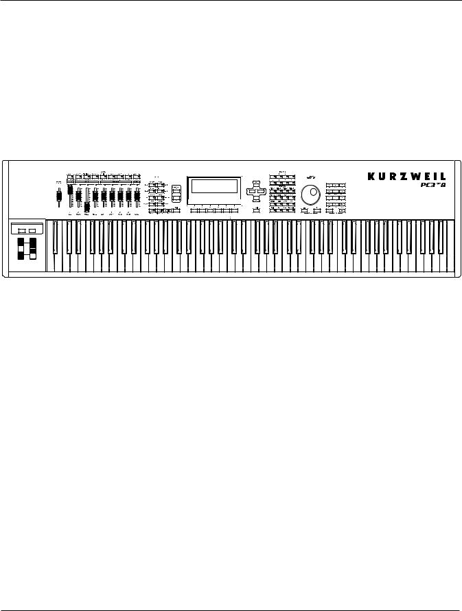
Pictured below is the 88-key PC3A8.
Arp
 SW
SW

The PC3A’s 1400+ programs include improved piano sounds from the German D Grand EXP expansion, and improved guitar, drums, synth, brass, and woodwind sounds from the KORE64 expansion. Also included are string sections from the Orchestral and Contemporary sound blocks, Stereo Triple Strike Piano, Classic Keys for realistic vintage electric piano sounds, and General MIDI (GM) sounds. Multi-zone performance setups are also provided; many of these setups use note triggers to play factory-recorded songs that provide grooves and arpeggiation that make great templates for performance or recording. An on-board sequencer with front panel transport buttons lets you record your ideas any time inspiration strikes. This sequencer (Song mode) lets you play back MIDI type 0 or 1 sequences, record and play back your own songs, and record multi-timbral sequences received via MIDI.
In addition to V.A.S.T. capability, a few of the features that by themselves make the PC3A an impressive stage and studio machine are:
•128-voice polyphony
•Fullymulti-timbralvoices,sothatdifferentprogramscanbeplayedoneachMIDIchannel.
•Anon-boarddigitaleffectsprocessorprovidesmultiplesimultaneouseffects,including real-timeeffectscontrol,internallyorviaMIDI.
•MoreeffectsprocessingpowerthanKurzweil’sownKSP8studioeffectsprocessor.
•Two additional balanced analog outputs in addition to the standard stereo audio output pair, as well as a digital output. All of the outputs are available simultaneously.
Forbackup,storage,andmovingfiles,twotypesofUSBportsareprovidedonthebackpanelof the PC3A. A USB storage port allows you to connect a USB device such as a thumb drive, and a secondUSBComputerportletsyouconnectthePC3AtoacomputerforfiletransferandMIDI connectivity.
1-2
Introduction
VA-1 Programs
VAST Synthesis
The PC3A’s Variable Architecture Synthesis Technology (V.A.S.T.) lets you build sounds from realistic instrumental samples and sampled synth waveforms—then modify the nature of those sounds through a wide variety of digital signal-processing (DSP) functions. The PC3A also generates its own synth waveforms, which can be combined with the samples or used on their own.
WhilemanyothersynthesizersmayofferafixedsetofDSPtools(typicallyfiltering,pitch,and amplitude modulation) the PC3A’s Variable Architecture lets you arrange a combination of DSP functionsfromalonglistofchoices.Thefunctionsyouchoosedefinethetypeofsynthesisyou use.
Each layer of every program has its own DSP architecture, which we call an algorithm. Within each algorithm, you can select from a variety of DSP functions. Each function can be independently controlled by a variety of sources including LFOs, ASRs, envelopes, a set of unique programmable functions (FUNs), as well as any MIDI control message. The many differentDSPfunctionsandthewealthofindependentcontrolsourcesgiveyouanextremely flexible,trulyvastcollectionoftoolsforsoundcreationandmodification.
ThePC3AofferspowerfuleditingfeatureswecallDynamicV.A.S.T.andCascadeMode.
DynamicV.A.S.T.allowsyouto“wire”yourownalgorithms,combiningdifferentDSPfunctions inanyorderyoulike,includingparallelandserialconfigurations.
Cascade Mode lets you route any layer of a program into the DSP of any other layer. Any of the 32 layers of a program can go into any other layer.
When you’re ready to jump in and start creating programs, turn to Chapter 6.
KB3 Tone Wheel Emulation
InadditiontoVASTsynthesis,thePC3Aoffersmanyoscillator-basedprogramsthatgiveyouthe classic sound of tone-wheel organs like the Hammond B3. KB3 mode, as we call it, is completely independent of VAST, and has its own set of editing procedures. Nine dedicated sliders on the PC3A’s front panel give you real-time drawbar control over these organ sounds. Buttons above the sliders control rotating speaker speed, percussion, and other organ features.
The quickest way to get to the KB3 programs is by pressing the KB3 button (above the sliders, to the left of the screen). The blue LED in the KB3 button will light when the current program is a KB3 program.
VA-1 Programs
TheVA-1(VirtualAnalogSynthesizer)programsincludedwiththePC3Aofferrealistic emulations of classic analog synthesizers, built from Kurzweil’s unique anti-aliased DSPgenerated oscillators. The PC3A’s power-shaped oscillators let you transition smoothly from one waveform into another in real time, without using cross-fades.
VA-1 programs are scattered throughout the PC3A. Look for them in the Synth Category and the Classic Keys Bank. You’ll see “KVA Oscillator” appear in the Keymap screen on the left hand side of the display.
1-3

Introduction
How to Use This Manual
This PC3A Musician’s Guide describes how to connect and power up your PC3A, and to hook up the PC3A to your sound system and MIDI system. It provides an overview of the front panel, and a brief description of the operating modes to help you start playing music with the instrument.ItcoversthePC3Ainits88,76,and61-noteconfigurations(PC3A8,PC3A7,and
PC3A6).
Detailed information on editing and advanced programming features is also provided on the Kurzweil website:
http://www.kurzweil.com
The best way to read this guide is with your PC3A in front of you. By trying the examples we give to illustrate various functions, you can get a quick understanding of the basics.
Do I Have Everything?
Your PC3A shipping carton should include the following in addition to your instrument:
•Power cable
•Sustain pedal
•USB cable
•Getting Started manual
If you don’t have all of these components, please call your Kurzweil/Young Chang dealer. You may also want to purchase a USB thumb drive for portable backups and storage.
Boot Loader
When you need to update the PC3A’s software or run diagnostic tests, you’ll use the Boot Loader. To bring up the Boot Loader, hold down the Exit button (below the cursor buttons, to the right of the display) while powering on your PC3A. Refer to Appendix BAppendix B, p.1 for details on the Boot Loader.
Battery
ThePC3AusesaCR2032batterytopoweritsclock.Thebatteryshouldlastfiveyears,anda
message will tell you when the battery needs replacing. The access panel on the bottom of the PC3A (which you can easily remove with a screwdriver) allows you to get at the battery for removal and replacement.
CAUTION: Danger of explosion if battery is incorrectly replaced. Replace only with the same or equivalent type (CR2032).
1-4

Introduction
Options
Ask your Kurzweil dealer about the following PC3A options:
Sound ROM Expansion Card
The PC3A has the KORE64 and German D Grand EXP cards installed as standard components.
Pedals
The PC3A has jacks for three switch pedals (for functions like sustain or program/setup changes) and two continuous pedals (for functions like volume control and wah). Your Kurzweil dealer stocks the following optional pedals:
FS-1 |
Standard box-shaped switch pedal |
KFP-1 |
Single piano-style switch pedal |
KFP-2M |
Double piano-style switch pedal unit |
CC-1 |
Continuous pedal |
Ribbon Controller
There’s a dedicated modular jack (like a telephone jack) on the rear panel of the PC3A for connectingthis600-mm(24 inch)ribboncontroller.YoucanconfigurethePC3Atousetheribbon as a single large controller, or a three-section controller with independent settings for each section.
Breath Controller
You can plug a Yamaha (or equivalent) breath controller into the dedicated jack on the PC3A’s rear panel.
USB Storage Device
You can plug a USB mass storage device such as a “thumb drive” or memory stick into the PC3A for backing up, archiving, sharing your work, and updating your software. Any size USB mass storage device will work, though thumb drives are recommended for their portability, durability, and low price.
Note: Most USB thumb drives are compatible with the PC3A, but some older USB thumb drives and larger USB bus powered drives will not work with the PC3A if they require more than 100 mA of current (high power USB devices). When attempting to use an incompatible USB device, the PC3A will display the message “USB device requires too much power.” The PC3A is designed to work with low power USB devicesandcanprovideamaximumof100mAtoaUSBdevice.Powerrequirementspecificationsfor thumb drives are not always made clearly available by the manufacturer, but a newly purchased thumb drivewillmostlikelybecompatible.Ifpossible,checkthepowerrequirementspecificationsofyourUSB device before purchase.
1-5
Startup
Make Music
Chapter 2
Startup
If hooking up new gear is familiar to you, and you just want to get going, here’s a quick description of what you need to get started with your PC3A. If you need more information, thorough descriptions of each step follow.
Make Connections
1.Setthekeyboardonahard,flat,levelsurface.Makesuretoleaveplentyofroomfor ventilation.
2.Four adhesive-backed rubber feet are provided with your PC3A. If you want to attach them to the bottom of the PC3A(recommended to prevent scratching your tabletop), carefully turn the keyboard over, remove the paper backing from the rubber feet and attach them now, near each corner, all on the same level.
3.Connect the power cable.
4.Make sure your sound system is at a safe volume level. Also make sure that the PC3A’s MASTER VOLUME slider (on the far left side of the front panel) is all the way down.
5.Plug in a pair of stereo headphones or run standard (1/4-inch) audio cables from your amplifierormixertotheMIXaudiooutputsonthePC3A.(UsetheMainLeftoutfor mono.) Balanced (“TRS” or “Stereo”) cables are recommended.
Make Music
6.Power up your PC3A, raise the level of the MASTER VOLUME slider, and check out some of the programs and setups. The PC3A starts up in Program mode by default. Press one of the mode buttons to the left of the display to switch modes.
7.If you hear distortion, reduce the gain on your mixing board, or use the pad if it has one.
8.Scroll through the program list with the Alpha Wheel, or the dedicated Category and Program buttons, and try the PC3A’s many sounds.
2-1

Startup
Startup—the Details
Startup—the Details
This section walks you through the hookup of your PC3A. We’ll take a look at the rear panel, then describe the power, audio, and other cable connections.
Before You Start...
Don’t connect anything until you make sure your PC3A is properly and safely situated. Also, if your PC3A has been out in the cold, give it time to warm up to room temperature before starting it, since condensation may have formed inside the PC3A. It is normal for the rear panel near the MIDI jacks to become warm after a while.
Connecting the Power Cable (Line Cord)
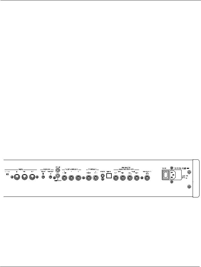
The PC3A runs on AC power: 100, 120, 230, or 240 volts at 50–60 Hz. Your dealer will set the voltage switch to match the voltage in your area. The voltage level is set with a selector on the rear panel of the PC3A. Unless you are sure it needs to be changed, you shouldn’t adjust this.
When you’ve connected the cable at the PC3A end (as you face the back of the PC3A, the power connection is at the right), plug it into a grounded outlet. If your power source does not have the standard three-hole outlet, you should take the time to install a proper grounding system. This will reduce the risk of a shock.
Connecting Audio Cables
Analog
After you’ve turned down the level on your sound system, connect the PC3A’s analog audio outputs to your sound system using a pair of stereo or mono audio cables. Mono cables will always work, but if you’re going into balanced inputs, use stereo cables for a better signal-to- noise ratio and a bit more volume. The PC3A’s analog outputs are balanced, and generate a “hotter” signal than some previous Kurzweil instruments.
You’llfindfour1/4-inchbalancedaudiooutputjacksontherearpanel.Fornow,connectoneend of each audio cable to your mixing board or PA system inputs, and connect the other end to the jacks marked Main Left and Right on the rear panel of the PC3A. If you have only one input available, use the PC3A’s Main Left output to get the full signal in mono.
In Master mode you can set the Aux outputs to duplicate the Main Outs – useful for monitoring and other operations. They are always in stereo, as is the headphone out.
2-2

Startup
Startup—the Details
Digital
For digital audio output from the PC3A, connect a 75-Ohm coaxial cable from the PC3A’s RCA Digital Out jack to the AES or S/PDIF input of the receiving device. You may need an RCA-to- XLR adapter to connect with the receiving device. If the receiving device receives only optical signals, you’ll need a converter as well. The PC3A’s Master Page (press the Master mode button) lets you select a range of useful sample rates for the digital output.
The RCA jack labeled “Sync In” allows you to synchronize the PC3A’s S/PDIF Digital Audio output sample rate to an external S/PDIF source. Although no audio signal is received by the “Sync In” jack, its clock is received and may be used to set the output sample rate. For details, see the Master Mode OUTPUT page parameter Digital Output (Dig. Out) in Ch. 11, page 10. NOTE: Sync In is NOT a “Word Clock” input. Only a valid S/PDIF signal is recognized.
Connecting MIDI
ThesimplestMIDIconfigurationusesasingle5-pinMIDIcable:eitherfromtheMIDIOutportof your PC3A to the MIDI In port of another instrument, or from the MIDI Out port of another MIDI controllertotheMIDIInportofthePC3A.Thereareallsortsofpossibleconfigurations, includingadditionalsynths,personalcomputers,MIDIeffectsprocessors,andMIDIpatchbays.
Depending on your system, you may want to use the PC3A’s MIDI Thru port to pass MIDI information from a MIDI controller to the PC3A and on to the next device in your system. You can also connect MIDI devices to the PC3A’s MIDI Out port, which can send channelized MIDI information from the keyboard or through the PC3A from your MIDI controller.
TheMIDIThruportcanbeconfiguredtoserveasanadditionalMIDIOutbyslidingthenearby switch to the Out position.
You can also use the PC3A’s USB port to send and receive MIDI. By default the PC3A will show up as a USB MIDI device. If you choose USB Temporary Drive from Storage mode, the PC3A will temporarily (while on that Storage mode page) become a “virtual storage device” and USB MIDI willbedisabled.Differenthostprogramsonyourcomputermayindicatevariouserrorsasthe
USB MIDI device is no longer present. Leaving Storage mode will restore USB MIDI functionality.
USB MIDI and 5-pin MIDI can be used at the same time; the MIDI signals will be combined into a single 16-channel MIDI stream.
2-3

Startup
Startup—the Details
Pedals
Plug your switch or continuous pedals into the corresponding jacks on the PC3A’s rear panel. We recommend using the Kurzweil pedals described on page 1-5, but you can use almost any switch orcontinuouspedal,aslongasitadherestothefollowingspecifications(asmostpedalsdo):
Switch pedals |
1/4-inch tip-sleeve plug |
Continuous pedals |
10-kOhm linear-taper potentiometer, 1/4-inch tip-ring-sleeve plug |
|
with the wiper connected to the tip. |
If you use a third-party (non-Kurzweil) switch pedal, make sure it’s connected before you turn onyourPC3A.Thisensuresthatthepedalwillworkproperly(itmightfunctionbackward—off when it’s down and on when it’s up—if you turn on your PC3A before plugging in the pedal).
Similarly,don’tpressanyofyourswitchpedalswhilepoweringup,becausethePC3Averifies each pedal’s orientation during power up. If you’re pressing a pedal, you might cause it to work backward.
The pedals are independently programmable within each zone of every setup. Here are the defaultsettingsforthefivepedalsyoucanusewiththePC3A:
Switch Pedal 1 |
Controller 64 |
(Sustain) |
Switch Pedal 2 |
Controller 66 |
(Sostenuto) |
Switch Pedal 3 |
Controller 67 |
(Soft) |
Continuous Control Pedal 1 Controller 11 (Expression / Volume)
Continuous Control Pedal 2 Controller 4 (Foot Pedal) producesa“wah”effectinmanysetups
Breath
The 3.5mm jack labeled Breath accepts a standard breath controller, which sends standard MIDI Breath (MIDI 2) messages. The PC3A’s preset programs and setups don’t respond to breath, but if you have other instruments that do respond to Breath, you can control them from the PC3A via MIDI.
YoucanalsoprogramthePC3AsothatthebreathcontrollersendsadifferentMIDImessage.This wouldenableyoutouseabreathcontrollertoaffectthePC3A,butthenotherinstruments receiving MIDI from the PC3A would no longer respond to the PC3A’s breath controller (unless you also programmed them to receive the same MIDI Controller that the PC3A’s breath controller is sending).
2-4

Startup
Startup—the Details
Ribbon
Plug the optional Kurzweil Ribbon Controller into the modular Ribbon jack on the rear panel.
Theribboncontrolleritselfshouldrestonaflatsurface;itfitsnicelybetweenthekeysandthe buttons and sliders on the front panel.
The ribbon is a continuous controller. You can program the ribbon controller to send MIDI Controller messages 1–127, as well as several specialized messages. It generates values of 0–127 forwhateverMIDIControllersyouassignittosend.Justpressit,andslideyourfingeralongthe ribbon to change the value of the message it’s sending.
Youcanconfiguretheribbontohaveonecontrolsectionthatrunsitsentirelength,ortohave three sections of equal length. It sends its highest values when you press it at the end where the cableconnects.Whenyouconfigureittohavethreesections,eachsectionsendsitshighestvalues at the end closest to the cable.
Caution: The modular jack is designed for connection to the Kurzweil Ribbon Controller option only. Don’t plug any other modular plugs into the Ribbon jack.
Switching On the Power
The PC3A’s power switch is on the rear panel, adjacent to the power cable connection.
Whenyoupowerup,thedisplaybrieflyshowssomestartupinformation.TheProgrammode displaythenappears.Itlookslikethediagrambelow,thoughyourPC3Amaybedifferentfrom the example.
Thefirsttimeyoupowerup(orafterareset),yourinstrumentwillbesettooperateonMIDI
Channel 1 (as shown at the far right of the top line above).
Set the volume at a comfortable level. You’ll get the best signal-to-noise ratio if you keep the PC3A at full volume, and adjust the level from your mixing board. You may also want to adjust the display contrast and brightness. There are two small knobs on the rear panel of the PC3A for this purpose.
2-5
Startup
Startup—the Details
USB Storage Port
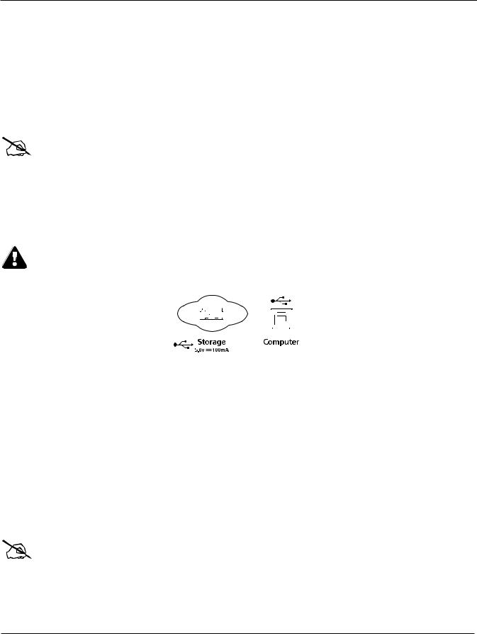
You can plug a USB mass storage device such as a “thumb drive” into the PC3A for backing up, archiving, sharing your work, and updating your software. Any size USB mass storage device will work, though thumb drives are recommended for their portability, durability, and low price. The USB Storage port is on the back panel of the PC3A, but it is easily accessible from the front of theinstrument.AUSBconnectorwillonlyfitintotheportiforientedproperly,sodon’tforceit into the port, as this may damage your PC3A or USB device. If you are having trouble inserting yourUSBconnectorintotheport,tryflippingtheconnectorover.
Note: Most USB thumb drives are compatible with the PC3A, but some older USB thumb drives and larger USB bus powered drives will not work with the PC3A if they require more than 100 mA of current (high power USB devices.) When attempting to use an incompatible USB device, the PC3A will display the message “USB device requires too much power”. The PC3A is designed to work with low power USB devicesandcanprovideamaximumof100mAtoaUSBdevice.Powerrequirementspecificationsfor thumb drives are not always made clearly available by the manufacturer, but a newly purchased thumb drivewillmostlikelybecompatible.Ifpossible,checkthepowerrequirementspecificationsofyourUSB device before purchase.
Caution: Do not remove a USB device while the display says Loading... or Saving.... Removing a USB deviceduringafiletransfercancausedatacorruption.
USB Computer Port
Next to the USB Storage port on the back panel of the PC3A is a USB Computer port. The USB Computer port works for MIDI (transmit and receive) or to connect your PC3A to a computer for filetransfer.Bydefault,theUSBportissettoMIDImode.WhenselectingUSBPCconnectionin
Storage mode, USB MIDI will temporarily be disabled.
We recommend that you use the USB cable provided with your PC3A and do not use extension USB cables. The PC3A’s USB Computer port is only intended for connection to a USB Type A port.
In USB Storage mode, a “PC3A” virtual drive will appear on your computer desktop. One important thing to know here is that this is a virtual drive. You can save to this drive from the
PC3A,butyoumustimmediatelytransferthatfiletoyourdesktop(orotherfolder).You must copy data from the PC3A virtual drive to your computer’s drive or else the data will be lost.
Note: WhentransferringfilestoandfromthePC3AviatheUSBComputerPort,themaximum size of filesthatcanbetransferredisapproximately1.6MB.Thisissuitableformostobjects. WhenusingtheUSBStoragePorttotransferfiles,thefilesizethatcanbetransferredislimited onlybythesizeoftheUSBmassstoragedeviceandthePC3A’savailableobjectmemory.
2-6

Startup
PC3A Programs
When you leave Storage Mode, there will be a prompt telling you that the PC3A is turning back into a USBMIDIdevice-whichyouhavetoacknowledge.Ifyouhaven’tcopiedthefile(s)to your desktop (or other place on the computer) it won’t be on the virtual disk when you leave storage mode.
Depending on your computer’s operating system, you may sometimes see a scary device removal warning on your desktop (for example, when the PC3A leaves the Boot Loader). You may disregard such a message without worries of damage to your PC3A or computer.
Setting the Clock
ThefirsttimeyoustartupyourPC3Aisprobablyagoodtimetosettheinstrument’sclockto your current local time. Do this from the Master mode CLOCK page.
Theclockwilltime-stampyourfilesthathavebeenstoredviaUSB.
PC3A Programs
The PC3A powers up in Program mode, where you can select and play programs (called patches, presets, or voices on other instruments). Programs are preset sounds composed of up to 32 layers of samples or waveforms. If you’ve left Program mode, just press the Program mode button or Exit button to return.
Selecting Programs
When you are in Program mode, there are three basic ways to select a PC3A program:
•Press one of the Bank buttons (above the sliders on the left side of the front panel) to select a bank, then press a Category button and a Program button. The Category and Program buttons are on the front panel, between the screen and the alpha wheel. Note: The instrument names above the Category buttons are relevant for Banks 1 and 2 (Base1and Base2). For all other Banks, the Category buttons select a group of 8 programs to be selected by the Program buttons, but the group of programs may not match the instrument name of the selected Category button. (See Program and Category Buttons in Ch. 3, page 4 for more details.)
•Type the program’s ID (number) on the alphanumeric buttonpad, then press Enter. If you make a mistake, press Clear, then start over.
•Scroll through the list using the Alpha Wheel, the Plus or Minus button under the Alpha Wheel, or the cursor buttons (the arrow buttons to the right of the display).
The PC3A has various settings for responding to MIDI Program Change commands from external sources. These are explained in Chapter10 , so we won’t go into them here. You should be able to change programs by sending Program Change commands from your MIDI controller.
Easy Audition
Any time you want to hear what a program sounds like, highlight the program’s name (while in
Program mode) then press the Play/Pause button to play a brief sample. The Demo Button parameter on the Master Mode MAIN page must be on for Easy Audition to work; the parameter is on by default. Master mode is described in Chapter 11.
2-7
 Loading...