


250 SX-MXC-EXC
Table of contents
 Loading...
250-525
SX, MXC, EXC RACING
REPAIR MANUAL
ENGINE
KTM SPORTMOTORCYCLE AG
5230 Mattighofen
Austria
www.ktm.at


REPAIR
MANUAL
ENGINE
250-525
SX, MXC,
EXC RACING


1 SERVICE-INFORMATIONS
2 GENERAL INFORMATION
3 REMOVING AND REFITTING ENGINE
4 DISASSEMBLING ENGINE
5 SERVICING INDIVIDUAL COMPONENTS
6 ASSEMBLING ENGINE
7 ELECTRICAL
8 FUEL SYSTEM
9 TECHNICAL SPECIFICATIONS
10 PERIODIC MAINTENANCE SCHEDULE
11 WIRING DIAGRAMS
12
13
14
15
16

Repair manual KTM 250-525 SX, MXC, EXC RACING Art.-No. 3206007 -E
IMPORTANT INFORMATION/UPDATING INSTRUCTIONS
To be able to continue using the existing loose-leaf repair instructions, simply print the following
pages and insert them in the existing repair instructions:
14, 21-24, 30-47, 50-52, 56-76, 79-92, 97-124, 134-140, 142, 150-154, 165-167
KTM REPAIR MANUAL IN LOOSE-LEAF FORM
STORING THE REPAIR MANUAL IN THE BINDER
– Put the index into the binder.
– Put the front page of the repair manual (210x297 mm) into the transparent pocket provided for
this purpose on the outside of the binder.
– Put the spine label (170x45 mm) into the transparent pocket provided for this purpose on the
spine of the binder.
– Put the summary list of contents (150x297 mm) into the transparent pocket provided for this
purpose on the inside of the binder or insert this page on the beginning of the manual.
– Then insert the individual chapters of the manual between the sheets of the index according to
the page number printed in the right bottom corner of each page.
Example: page no. 3-5 3 = chapter 3 5 = page 5
All pages with a page number that begins with the digit 3, for example, must be put under the
index heading „Chapter 3“.
– Index sheets that have not been marked with a certain chapter are for your personal convenience. T
he
respective headings can be entered in the list of contents.
Remove page (s) Replace by page (s) Insert page (s) after page
2-1 / 2-7 2-1C 2-7C to 2-9C
3-1 3-1C
4-1 to 4-14 4-1C to 4-13C
5-1 / 5-3 5-1C / 5-3C
5-6 to 5-8 5-6C to 5-8C
5-12 to 5-26 5-12C to 5-27C
6-1 / 6-4 6-1C / 6-4C
6-7 to 6-16 6-7C to 6-17C
7-1 to 7-2 7-1C to 7-2C
7-7 to 7-11 7-7C to 7-11C
8-1 to 8-13 8-1C to 8-21C
9-1 9-1C
9-10 to 9-13 9-10C to 9-16C
10-1 10-1C 10-8C to 10-11C
11-1 11-1C 11-11C to 11-13C


Repair manual KTM 250-525 SX, MXC, EXC RACING Art.-No. 3206007 -E
EXPLANATION - UPDATING
Edition 01/2003
3.205.85-E Repair Manual
400/520 SX, MXC, EXC RACING
Basic version Model year 2000
(Engine number with first digit “0“)
2/2000
3.210.01-E Updating of Rep.Manual 3.205.85-E
Model year 2001
(Engine number with first digit “1“)
1/2001
3.210.44-E Updating of Rep.Manual 3.205.85-E
Model year 2002
(Engine number with first digit “2“)
2/2002
3.206.007-E Updating of Rep.Manual 3.205.85-E
Model year 2003
(Engine number with first digit “3“)
1/2003
Modification / Updating:
Technical Details Model 2003 (clutch, valve spring, camshaft gear,
carburetor)
Technical Specifications, Periodic Maintenance Schedule, Wiring Diagrams


INTRODUCTION
This repair manual offers extensiv repair-instructions and is an up-to-date version that describes the
latest models of the series. However, the right to modifications in the interest of technical
improvement is reserved without updating the current issue of this manual.
A description of general working modes common in work shops has not been included. Safety rules
common in the work shop have also not been listed. We take it for granted that the repairs are made
by qualified profesionally trained mechanics.
Read through the repair manual before beginning with the repair work.
WARNING
STRICT COMPLIANCE WITH THESE INSTRUCTIONS IS
ESSENTIAL TO AVOID DANGER TO LIFE AND LIMB.
!
CAUTION
!
NON-COMPLIANCE WITH THESE INSTRUCTIONS CAN LEAD TO
DAMAGE OF MOTORCYCLE COMPONENTS OR RENDER
MOTORCYCLES UNFIT FOR TRAFFIC !
„NOTE” POINTS OUT USEFUL TIPS.
Use only ORIGINAL KTM SPARE PARTS when replacing parts.
The KTM high performance engine is only able to meet user expectations if the maintenance work is
performed regularly and professionally.
KTM Austria’s certificate of achievement for its quality system ISO 9001 is the beginning of an
ongoing total reengineered quality plan for a brighter tomorrow.
KTM Sportmotorcycle AG
5230 Mattighofen, Austria
All design and assembly modification rights reserved.
C
by KTM SPORTMOTORCYCLE AG, AUSTRIA All rights reserved

REPLY FAX FOR REPAIR MANUALS
We have made every effort to make our repair manuals as accurate as possible but it is always possible for
a mistake or two to creep in.
To keep improving the quality of our repair manuals, we request mechanics and shop foremen to assist us
as follows:
If you find any errors or inaccuracies in one of our repair manual – whether these are technical errors,
incorrect or unclear repair procedures, tool problems, missing technical data or torques, inaccurate or
incorrect translations or wording, etc. – please enter the error(s) in the table below and fax the completed
form to us at 0043/7742/6000/5349.
NOTE to table:
– Enter the complete item no. for the repair manual in column 1 (e.g.: 3.210.66-E).
You will find the number on the cover page or in the left margin on each right page of the manual.
– Enter the corresponding page number in the repair manual (e.g.: 5-7c) in column 2.
– Enter the current text (inaccurate or incomplete) in column 3 by quoting or describing the respective
passage of the text. If your text deviates from the text contained in the repair manual, please write your
text in German or English if possible.
– Enter the correct text in column 4.
Your corrections will be reviewed and incorporated in the next issue of our repair manual.
Item no. of repair manual Page Current text Correct text
Additional suggestions, requests or comments on our Repair Manuals (in German or English):
Name mechanic/shop foreman Company/work shop

GENERAL INFORMATION
Repair manual KTM 250-525 SX, MXC, EXC RACING
Art.-No. 3206007 -E
OIL CIRCUIT . . . . . . . . . . . . . . . . . . . . . . . . . . . . . . . . . . . . . . . . . . . . . .2-2
ENGINE OIL . . . . . . . . . . . . . . . . . . . . . . . . . . . . . . . . . . . . . . . . . . . . . . .2-3
CHECKING THE ENGINE OIL LEVEL . . . . . . . . . . . . . . . . . . . . . . . . . . . . .2-3
CHANGING THE ENGINE OIL . . . . . . . . . . . . . . . . . . . . . . . . . . . . . . . . . .2-4
CHANGING THE OIL FILTERS . . . . . . . . . . . . . . . . . . . . . . . . . . . . . . . . . .2-5
CHECKING THE OIL LEVEL OF THE HYDRAULIC CLUTCH . . . . . . . . . . . .2-6
BLEEDING OF THE HYDRAULIC CLUTCH . . . . . . . . . . . . . . . . . . . . . . . . .2-6
SPECIAL TOOLS . . . . . . . . . . . . . . . . . . . . . . . . . . . . . . . . . . . . . . . . . . . .2-7
CLEANING, STORAGE OF MOTORBIKE . . . . . . . . . . . . . . . . . . . . . . . . . .2-9
INDEX
2-1C
2

2-2C
Repair manual KTM 250-525 SX, MXC, EXC RACING Art.-No. 3206007 -E
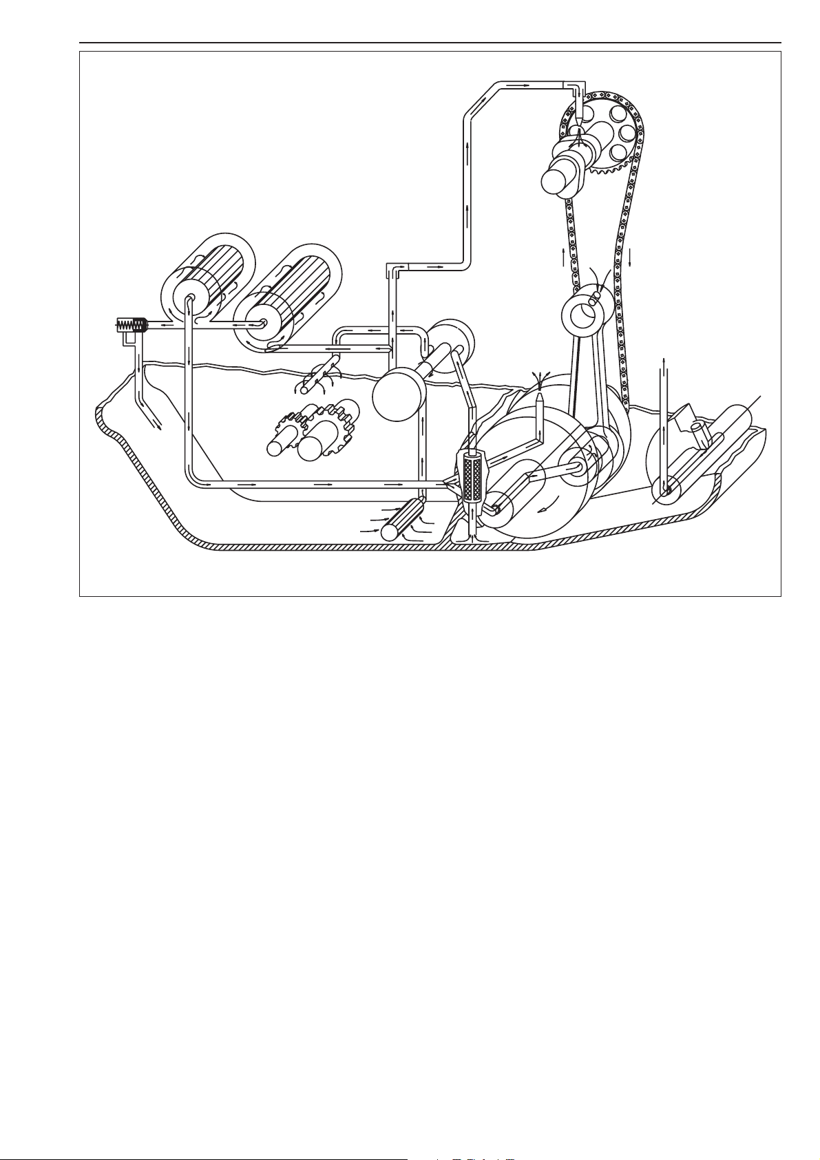
Oil circuit
Via the long oil screen 2, the oil pump 1draws engine oil from the oil sump of the transmission. This engine
oil flows through an oil line
3
into the cylinder head for camshaft lubrication 4; the oil quantity is controlled
by the jet bolt
5
. An oil duct branches off to the long oil filter 6where the coarser particles contained in
the engine oil are filtered away. Then, the engine oil arrives at the short oil filter
7
which also filters the fine
particles.
Now, the purified engine oil is pumped past the bypass valve
8
to the conrod bearing 9and sprayed from
below onto the piston through a nozzle
bk
.
The second oil pump
bl
draws the engine oil via the short oil screen bmout of the crankcase, thereby
lubricating the transmission gears
bn
.
7
6
9
8
13
2
12
10
11
1
4
3
5
Engine oil
Only use fully synthetic brand oils (Motorex Power Synt. 4T) that meet
or surpass the quality requirements of API classes SG or SH (see
specifications on the container).
!
CAUTION
!
I
NSUFFICIENT AMOUNTS OR LOW-GRADE ENGINE OIL LEAD TO PREMATURE WEAR OF
THE ENGINE
.
Checking the engine oil level
The engine oil level can be checked with the engine being either warm or
cold. Place the motorcycle in an upright position and on a horizontal
surface (not on the side stand).
If the engine is cold, the engine oil must be visible at the lower edge of
the inspection glass
A.
If the engine is warm, the engine oil must be visible up to the upper edge
of the inspection glass
B.
Replenish the engine oil, if necessary.
!
CAUTION
!
I
NSUFFICIENT AMOUNTS OR LOW
-GRADE ENGINE OIL LEAD TO PREMATURE WEAR OF
THE ENGINE
.
NOTE: Engines up to the 2001 model have a sight glass and an oil
dipstick. If the inspection glass is heavily soiled (e.g. after a race in muddy
terrain), the engine oil level can also be measured with the oil dipstick.
For this purpose, unscrew the dipstick and wipe it clean with a cloth.
Screw the dipstick back in and screw it out again. If the engine is warm,
the oil level should be near the MAX mark
C.
Check engine for leaks.
2-3C
–
+
0°C
32°F
15W 40
15W 50
10W 40
10W 50
API: SG, SH
TEMPERATURE
A
B
C
Changing the engine oil
NOTE: When changing the engine oil, it is necessary to clean the short
and long oil screens and to replace both oil filters.
Engine oil has be changed with the engine being at an operating
temperature.
WARNING
A
N ENGINE AT OPERATING TEMPERATURE AND THE ENGINE OIL IT CONTAINS ARE VERY
HOT
- DO NOT BURN OR SCALD YOURSELF!
Place the motorcycle on a horizontal surface, remove the plug
1 and
allow the oil to drain into a receptacle.
Clean plug (with magnet) thoroughly.
Once the entire oil has been drained, clean the sealing surface, mount the
plug together with the sealing ring and tighten it to 20 Nm/
15ft.lb.
CLEANING THE SHORT OIL SCREEN
The short oil screen
2 is accommodated in the hex-socket plug 3 on the
engine bottom.
Insert a pin-type key into the plug and tap on the key a few times with a
hammer in order to relieve the stress acting on the plug.
Dismount the oil screen, clean the components thoroughly and blow
compressed air through them.
Check the O-rings for damage and, if necessary, replace them.
Mount the oil screen together with the plug again and tighten the plug
to 10 Nm.
CLEANING THE LONG OIL SCREEN
The long oil screen is accommodated in the hexagon plug
4 adjacent the
engine number.
Dismount the plug together with the oil screen, clean the
components thoroughly and blow compressed air through them.
Check the O-rings for damage and, if necessary, replace them.
To mount the long oil screen
5, place it on an approx. 300 mm/
11.8 in long pin-type key or a similar tool. Insert the pin-type key through
the opening into the bore of the opposite engine casing wall. Then, push
the oil screen into the engine casing as far as possible.
Remove the pin-type key, mount the plug and tighten it to 15 Nm/
11 ft.lb.
!
CAUTION
!
THE OIL SCREEN IS MOUNTED SLIGHTLY DOWNWARDS, IF INCORRECTLY FITTED, THE
SCREEN LOOSES ITS FUNCTION AND THIS CAN CAUSE INCREASED ENGINE WEAR
.
2-4C
Repair manual KTM 250-525 SX, MXC, EXC RACING Art.-No. 3206007 -E
1
4
2
3
5
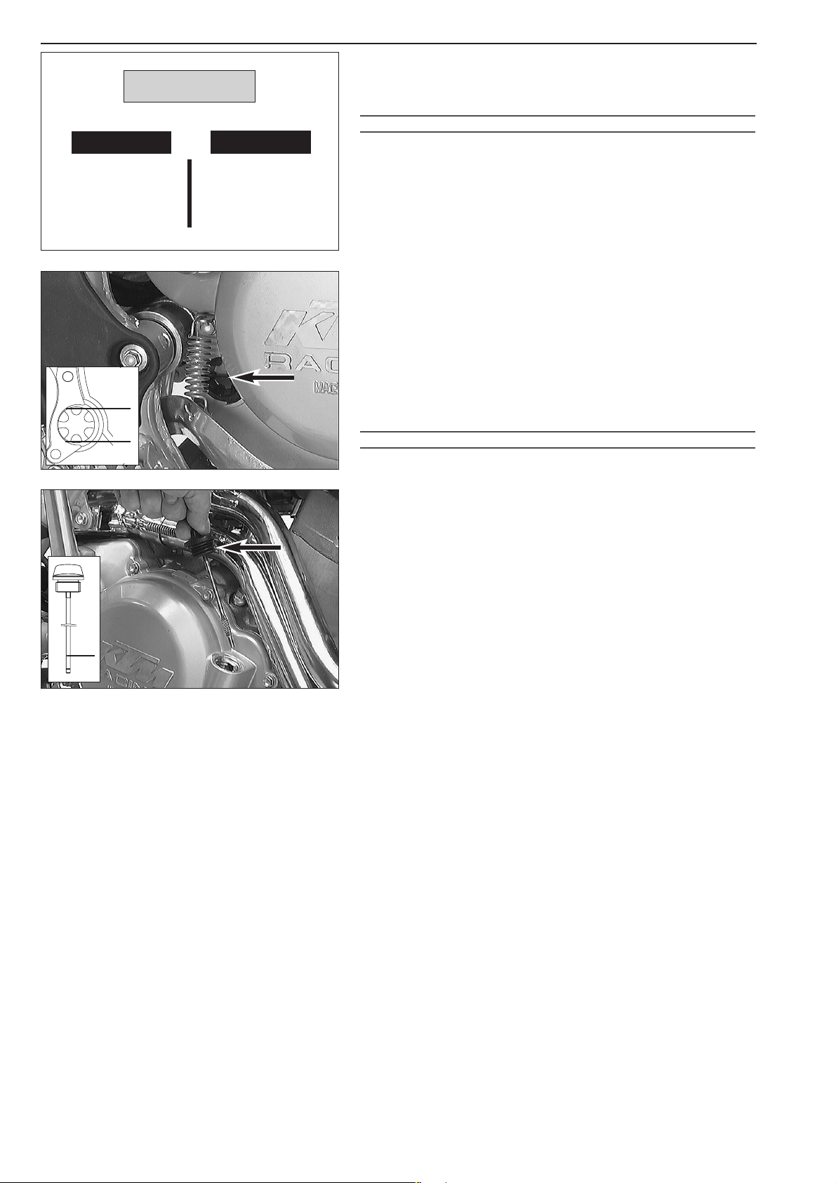
Changing the oil filters
Remove the bolt 1 and swing the brake fluid container sideward. Place
a receptacle underneath the engine to collect the drained oil.
Remove the 4 bolts
2 and dismount the two oil filter covers.
Using circlip pliers, you may now pull the oil-filter inserts
3 out of the
housing.
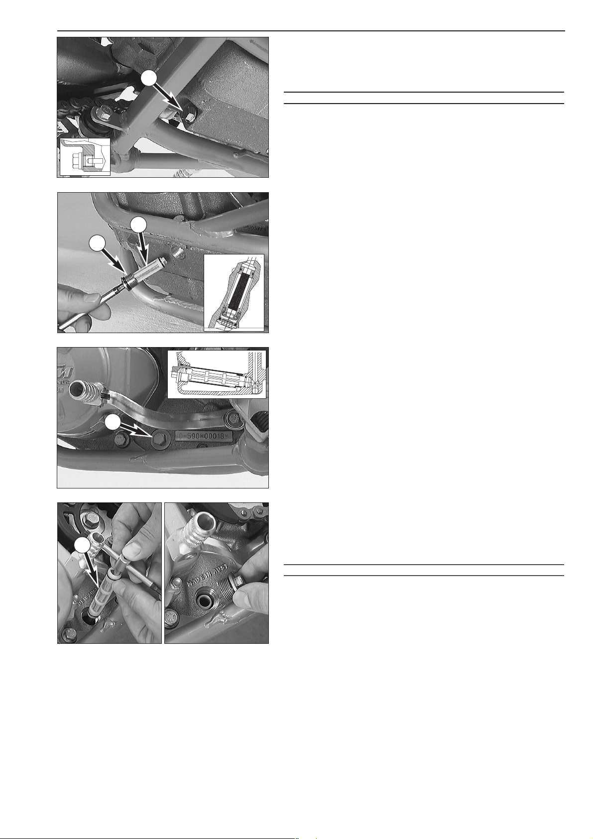
Clean the oil filter cover, the sealing surfaces of the O-rings and the
engine casing.
Check the O-rings of the oil filter covers for damage and, if necessary,
replace them.
Put the motorcycle on its side and fill the oil filter housings about halfway
with engine oil. Insert the long oil filter at the front and the short oil filter
at the back of the housing.
Grease the O-rings
4 of the oil filter covers and mount the cover. Mount
the bolts and tighten them to 6 Nm/5 ft.lb.
Position the brake fluid container and tighten the bolt to 8 Nm/
6 ft.lb.
Return the motorcycle to an upright position.
Remove the oil dipstick
5 at the clutch cover and fill in 1.2 liters of fully
synthetic engine oil (Motorex Power Synt. 4T).
Start the engine and check all screwed connections and oil filter covers for
leaks.
Finally, check the engine oil level and, if necessary, correct it.
2-5C
1
2
2
2
2
3
3
4
5
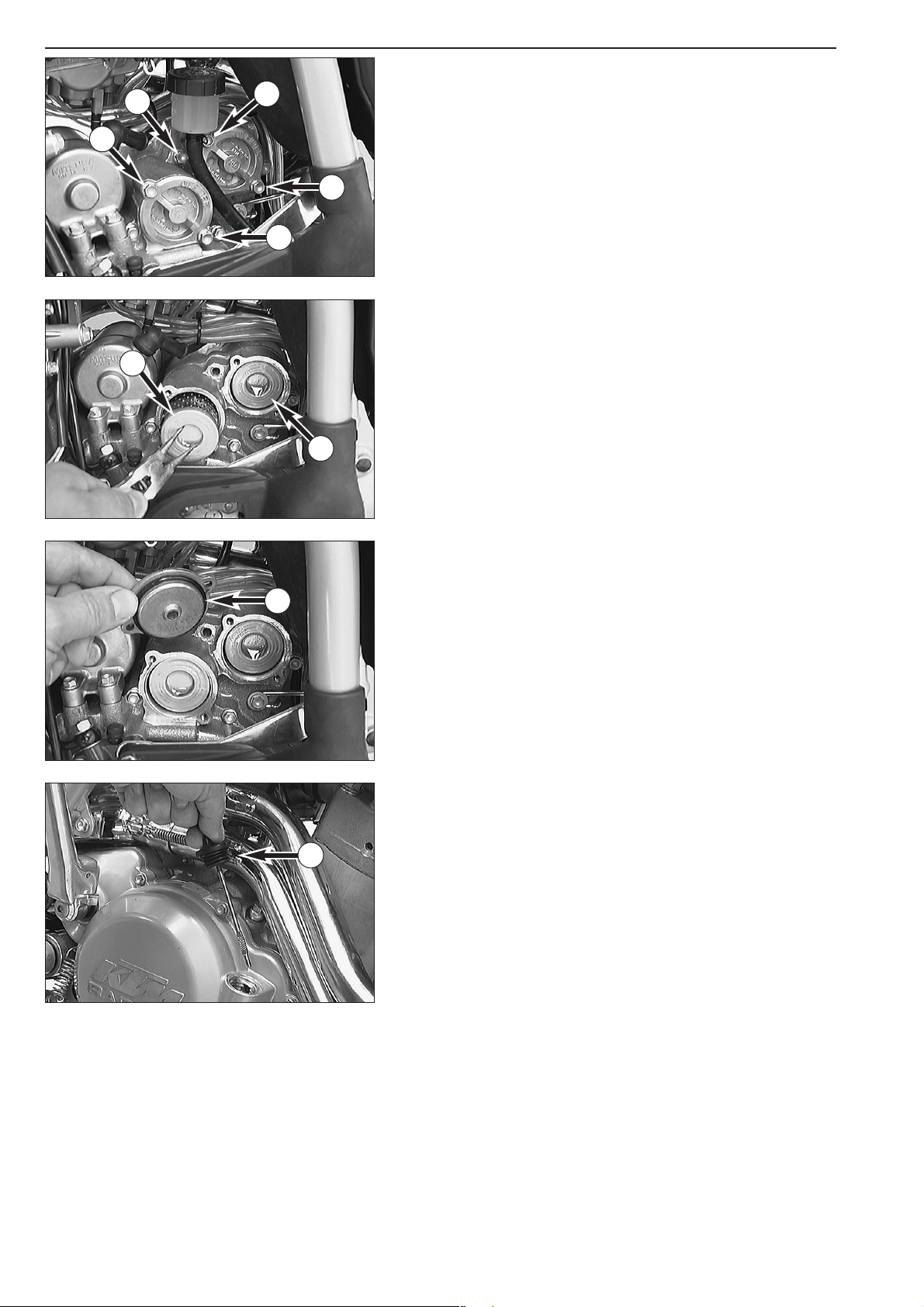
Checking the oil level of the hydraulic clutch
To check the oil level in the master cylinder of the clutch remove the
cover. For this purpose, remove bolts
1 and cover together with the
rubber boot
2. The oil level in the horizontal-standing master cylinder
should be 4 mm (0,157 in) below the upper edge. If necessary add SAE
10 biodegradable hydraulic oil.
!
CAUTION
!
O
NLY USE SAE 10 BIODEGRADABLE HYDRAULIC OIL TO REFILL THE MASTER CYLINDER.
N
EVER USE BRAKE FLUID!
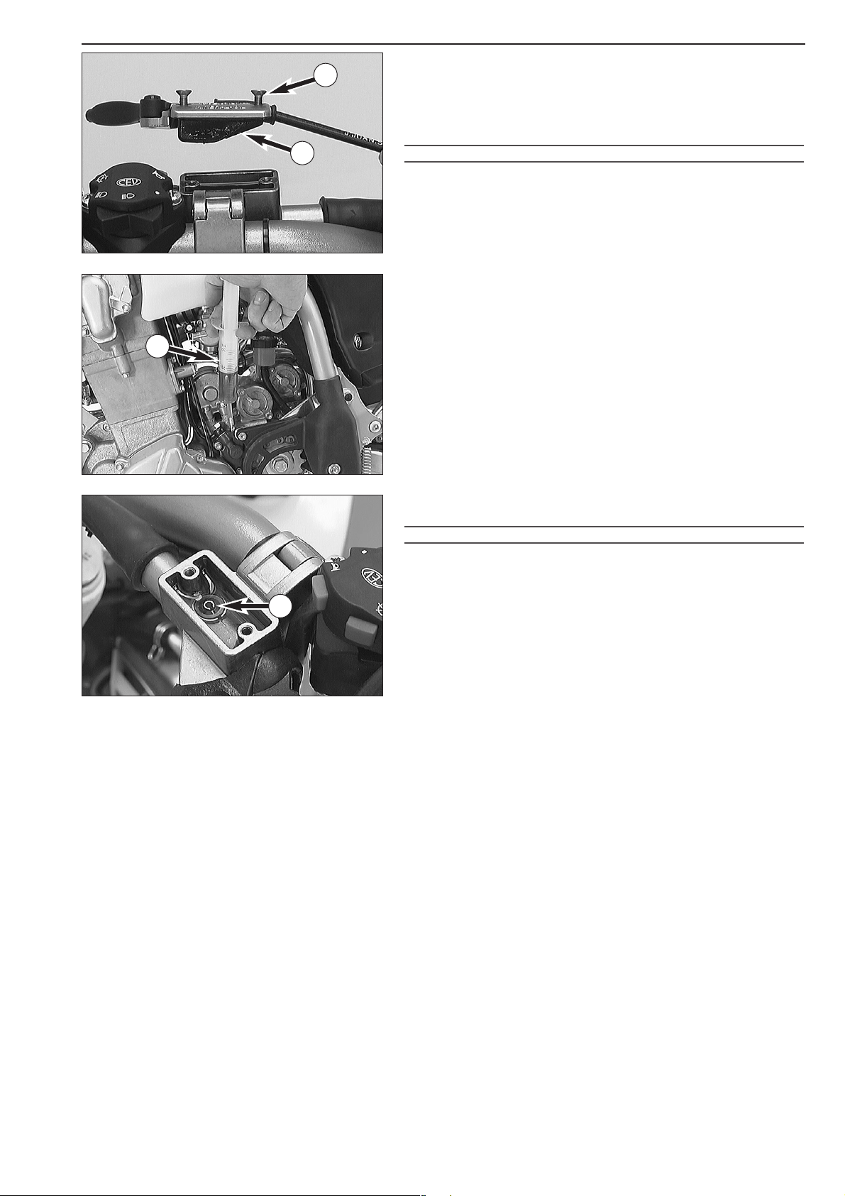
Bleeding of the hydraulic clutch
For bleeding, the cover of the master cylinder of the clutch needs to be
removed. For this purpose, remove screws
1 and take off cover together
with rubber bellows
2. At the slave cylinder of the clutch, remove the
bleeder nipple. At its place, mount the bleeder syringe
3 which is filled
with biodegradable hydraulic oil.
Refill oil, until oil is discharged from the bore
A of the master cylinder in
a bubble-free state. Make sure that the oil does not overflow.
!
CAUTION
!
H
AVING COMPLETED THE BLEEDING PROCEDURE
, YOU HAVE TO VERIFY THAT THE OIL
LEVEL IN THE MASTER CYLINDER IS CORRECT
. FOR FILLING OF THE MASTER CYLINDER,
USE SAE 10 BIODEGRADABLE HYDRAULIC OIL ONLY. NEVER USE BRAKE FLUID NOR MIX
BIODEGRADABLE HYDRAULIC OILS WITH MINERAL OILS
.
2-6C
Repair manual KTM 250-525 SX, MXC, EXC RACING Art.-No. 3206007 -E
A
1
2
3

2-7C
1
2
3
4
21
23
6
7
8
9
10
11
12
13
14
15
16
17
18
19
20
5
22
24

2-8C
Repair manual KTM 250-525 SX, MXC, EXC RACING Art.-No. 3206007 -E
FIG PART NO. DESCRIPTION
1 560.12.001.000 Universal engine work stand
2 590.29.002.000 Engine holder for engine work stand
3 590.29.020.000 Rivetting tool for steering chain
4 590.29.005.010 Mounting sleeve for shaft seal ring water pump
5 510.12.011.000 Circlip pliers
6 590.29.021.000 Puller for driving hub and primary gear
7 598.29.015.075
Piston ring spanner
Ø 75 mm
580.12.015.089 Piston ring spanner Ø 89 mm
580.12.015.095 Piston ring spanner Ø 95 mm
86 899 785 Loctite 243 blue 6 cm
3
584.29.059.000 Loctite 648 green 20 ml
9 151.12.017.000 Gear puller
10 151.12.018.000 Internal gear puller 12-16 mm
151.12.018.100 Internal gear puller 18-23 mm
11 590.29.026.006 Limit plug gauge 6.05 mm
12 590.29.035.000 Mounting sleeve for driving pin
13 590.29.036.000 Protection sleeve for primary gear
14 590.29.033.000 Puller for camshaft bearings
15 590.29.019.000 Valve spring mounter
16 584.29.037.037 Mounting tool for inner rings of crankshaft bearings
17 590.29.034.000 Wrench for mixture regulating screw
18 580.12.009.000 Magneto extractor
19 309098 Seal (Three-Bond)
20 510.12.012.000 Chain sprocket holder
21 590.29.072.000 Spark plug wrench 16 mm
22 503.29.050.000 Bleeding syringe for hydraulic clutch
23 590.29.041.000 Feeler gauge for valve clearance
24 590.29.003.100 Clutch holder
SPECIAL TOOLS
– ENGINE

2-9C
Should you desire to make a pause over a longer space of time, please observe the following instructions:
– Clean motorcycle thoroughly.
– Change engine oil, short and long oil filters (old engine oil contains aggressive contaminants).
– Check antifreeze and amount of cooling liquid.
–Warm up the engine once again, close the fuel cock and wait until the engine dies. Then open the drain plug from the float
chamber to remove the remaining fuel.
– Remove spark plug and fill in approx. 5 cc of engine oil into the cylinder through the opening. Actuate kick-starter 10 times in
order to distribute the oil onto the cylinder walls and mount the spark plug.
– Set piston to compression so that the valves will be closed (slowly operate the kickstarter until you can hear the automatic
decompressor click (release).
– Let fuel flow out of tank into an appropriate container.
– Correct tire pressure.
– Lubricate pivot points of the control levers, footrests, etc. as well as the chain.
– Service the shock absorber linkage.
– Disassemble and charge battery.
– The storage place should be dry and not subject to excessive temperature fluctuations.
– Cover the motorcycle with an air permeated tarpaulin or blanket. Do not use non air permeable materials as any humidity may
not be able to escape and could cause corrosion.
!
CAUTION
!
DO NOT LET THE ENGINE RUN FOR A SHORT TIME DURING THE STORAGE PERIOD. THE ENGINE WOULD NOT GET WARMED UP ENOUGH AND THE THUS
DEVELOPED STEAM WOULD CONDENSE DURING THE COMBUSTION PROCESS AND CAUSE THE VALVES AND EXHAUST TO RUST
.
RE-INITIATION AFTER TIME OF STORAGE
– Mount the charged battery (match polarity).
– Fill up tank with fresh fuel.
– Check motorcycle as before each start (see driving instructions).
–Take a short, careful test ride first.
STORAGE
Clean your motorcycle regularly in order to maintain the beauty of its plastic surfaces.
The best manner would be to use warm water that has been mixed with a normal brand-name washing detergent and a sponge.
The hard dirt can be removed before washing with the help of a soft water jet.
!
CAUTION
!
NEVER CLEAN YOUR MOTORCYCLE WITH A HIGH
-PRESSURED CLEANER OR A HIGH-PRESSURED WATER JET. THE WATER COULD OTHERWISE RUN INTO THE
ELECTRICAL COMPONENTS
, CONNECTORS, SHEATHED CABLES, BEARINGS, CARBURETOR, ETC. AND CAUSE DISTURBANCES OR LEAD TO A PREMATURE
DESTRUCTION OF THESE PARTS
.
–You should use normal brand-name detergents to clean the motorcycle. Especially dirty parts should be cleaned additionally with
the help of a paint brush.
– Before cleaning with water, plug the exhaust pipe to prevent water ingress.
– After the motorcycle has been rinsed with a soft water jet, it should be dried by air pressure and a cloth. Drain the float chamber
of the carburetor. Then take a short drive until the engine has reached the working temperature and also apply the brakes. By
warming these components, the residual water can evaporate from inaccessable parts of the engine and the brakes.
– Slide back the protective covers on the handlebar-mounted instruments so that any water that may have seeped into this part of
the motorcycle is allowed to evaporate.
– Once the motorcycle has cooled down, oil or grease all sliding and bearing points. Treat the chain with a chain spray. Also oil the
fuel tap.
–To avoid malfunctioning of the electric system, you should treat the emergency-OFF switch, short-circuit button, light switch and
socket connectors with a contact spray.
CLEANING
In the event that the motorcycle is also used in winter and on roads where one has to expect salt spraying, you will have to take
precautions against the aggressive road salt.
– clean motorcycle thoroughly and let it dry after each ride.
–treat engine, carburetor, swing arm, and all other bare or galvanized parts (except for brake discs) with a wax-based anti-corro-
sion agent.
WARNING
K
EEP ANTI-CORROSION AGENT FROM GETTING INTO CONTACT WITH THE BRAKE DISCS, FOR OTHERWISE THIS WILL SIGNIFICANTLY REDUCE THE BRAKING
POWER
.
!
CAUTION
!
AFTER RIDES ON SALTED ROADS, CLEAN MOTORCYCLE THOROUGHLY WITH COLD WATER AND LET IT DRY WELL!
CONSERVATION FOR WINTER OPERATION

Repair manual KTM 250-525 SX, MXC, EXC RACING
Art.-No. 3206007 -E
DISMOUNTING THE ENGINE . . . . . . . . . . . . . . . . . . . . . . . . . . . . . .3-2
MOUNTING THE ENGINE . . . . . . . . . . . . . . . . . . . . . . . . . . . . . . . . .3-5
BLEEDING THE COOLING SYSTEM . . . . . . . . . . . . . . . . . . . . . . . . . .3-5
CHECKING THE ADJUSTMENT OF THE HAND DECOMPRESSION
RELEASE CABLE . . . . . . . . . . . . . . . . . . . . . . . . . . . . . . . . . . . . . . . .3-5
ADJUSTING THE THROTTLE CABLES . . . . . . . . . . . . . . . . . . . . . . . .3-5
INDEX
DISMOUNTING AND MOUNTING THE ENGINE
3-1C
3

Repair manual KTM 250-525 SX, MXC, EXC RACING Art.-No. 3206007 -E
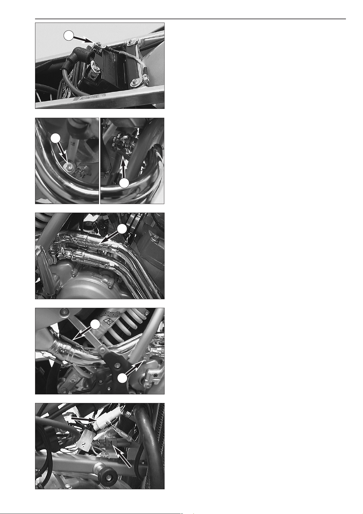
Dismounting the engine
– Clean the motorcycle thoroughly and prop it up on a stable stand.
– Dismount the seat and the tank with spoilers.
– Disconnect the ground cable
1 of the battery.
– Remove the screw
2 and detach the 2 tension springs 3.
– Detach the 2 tension springs
4, pull exhaust pipes forward and take
them off the vehicle.
– Detach the 2 tension springs
6 and remove the screw 5.
– Pull the intermediate pipe forward and take it off the vehicle.
– Disconnect all plug-and-socket connections of the ignition system.
– Unhitch the cable of the hand decompressor at the engine.
– Pull out the spark plug connector.
3-2C
1
2
3
4
5
6
– Remove the carburetor cover and unhitch both throttle cables.
– Detach the return spring
1 of the footbrake pedal.
– Remove the 2 screws
2 and take off the frame cover.
– Open the radiator cap.
– Remove the screw
3 at the cylinder together with the sealing ring and
drain the coolant into a receptacle.
– Disconnect the water hoses
4 and 5.
– Disconnect the hose of the engine ventilation system
6.
– Disconnect the plug-in connection from the throttle-valve sensor.
– Loosen the front and rear hose clamps of the carburetor, pull the
carburetor backward and pivot it out of the rubber sleeve at the front.
–Take the carburetor off the vehicle.
– Disconnect the cable
7 from the E-starter motor.
– Disconnect the plug-and-socket connection
8.
– Remove the screw
9 and swing the brake-fluid container sideward.
3-3C
1
2
3
4
5
6
7 8
9
Repair manual KTM 250-525 SX, MXC, EXC RACING Art.-No. 3206007 -E
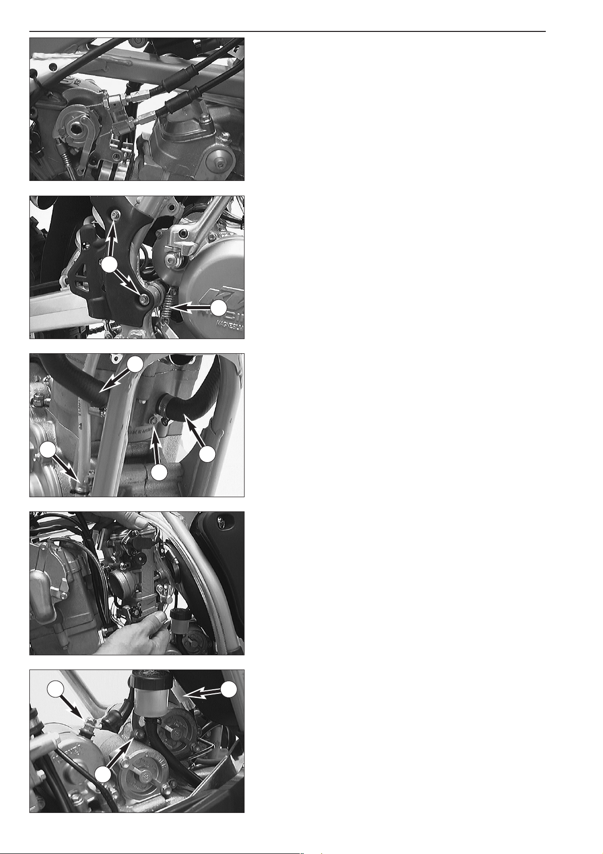
– Remove the bolts 1 and take off the sprocket cover.
– Remove the 2 bolts
2 of the clutch slave cylinder and pull the clutch
slave cylinder off the casing.
– Swing the chain damper plate backwards.
– Open the chain joint and remove the chain from the vehicle.
– Remove the bolt
3 and take off the cable clip.
NOTE: From Model 2001 onwards a cable tie is mounted instead of the
the cable clip.
– Disconnect the radiator hose
4 and dismount the tank roller 5.
– Dismount the front engine mounting bolt
6.
– Remove the engine mounting bolt
7 and the hex nut 8.
– Dismount the swing arm pivot and pull the swing arm backwards.
– Lift the engine out of the frame.
3-4C
1
2
1
3
4
5
6
7
8
Mounting the engine
– The engine is mounted exactly the reverse order. Be sure to use the
correct fastening torques (see technical specifications).
– After a short, careful test ride, check engine oil and coolant level once
more.
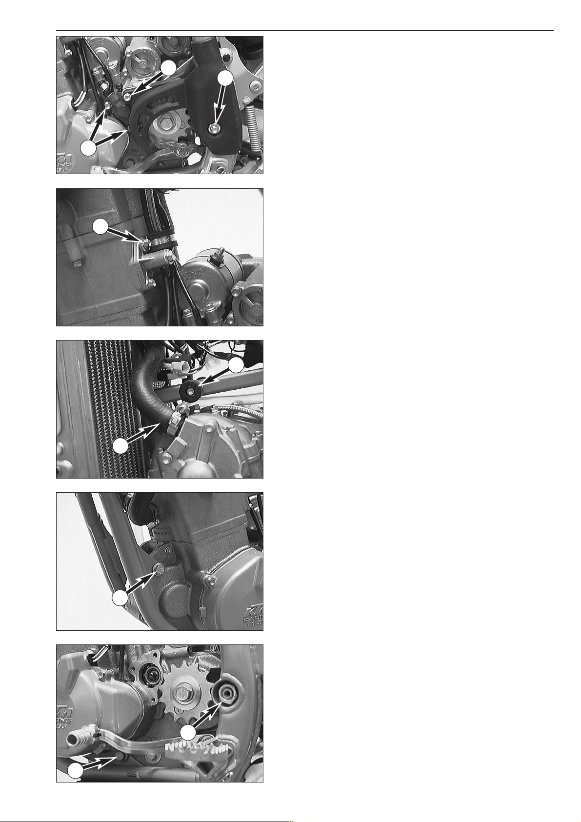
Bleeding the cooling system
To bleed the cooling system, fill in approx. 0.8 liters (0.2 US gallons) of
coolant and remove the bleeder bolt
1. Do not reinstall the bleeder bolt
until coolant escapes at the bore without any bubbles.
Then, fill in the coolant until it reaches a level about 10 mm above the
radiator fins.
After a short ride, check the coolant level once more.
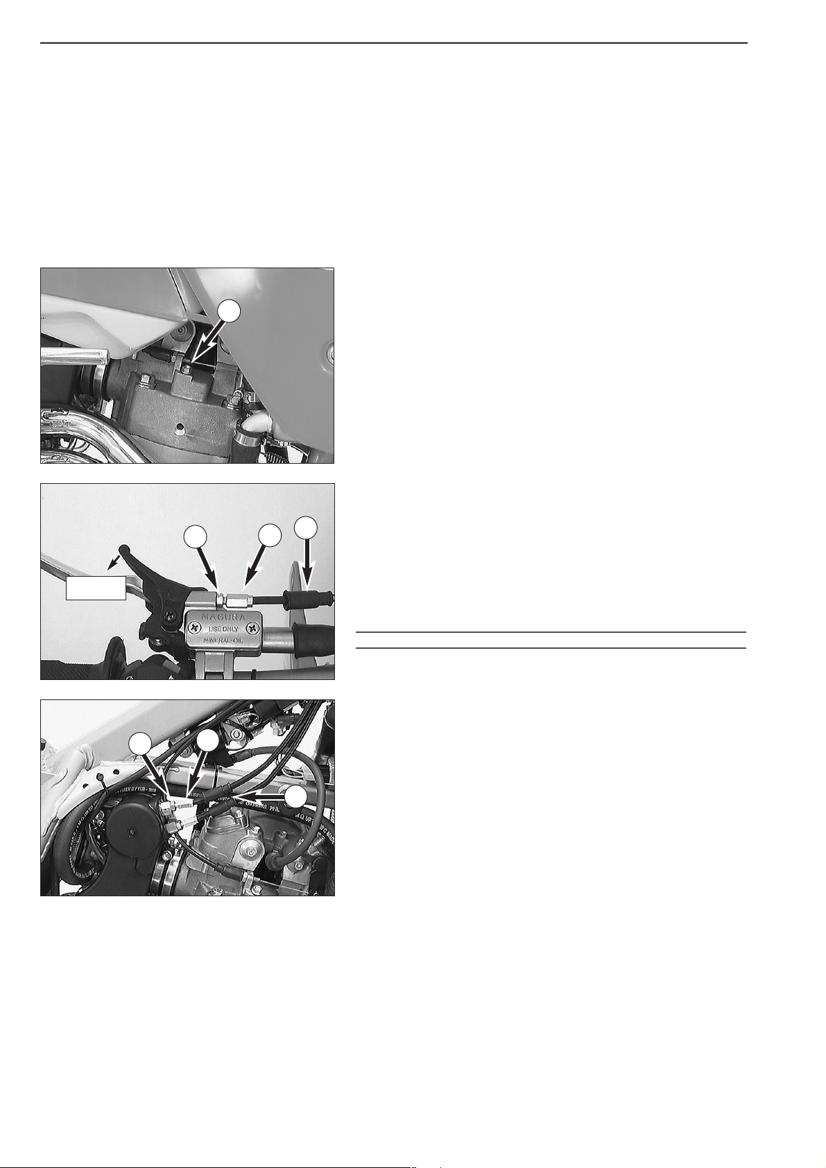
Checking the adjustment of the hand decompression release cable
Start the engine and, at idling speed, slowly pull the hand
decompression lever until you can feel the thumping of the rocker arm on
the lever. The backlash until said thumping should be approx.
10 mm, measured at the lever's outer end. If necessary, correct this
backlash.
To adjust move back the protective cover
2, loosen the counter nut 3
and correct the adjustment screw 4 accordingly. Tighten counter nut and
push back protective cover.
!
CAUTION
!
IF THERE IS NO PLAY IN THE DECO
-LEVER, THIS CAN RESULT IN ENGINE DAMAGE.
Adjusting the throttle cables
The throttle grip should always provide for a backlash of 3-5 mm.
Besides, with the engine running, the idling speed must not change if you
turn the handlebar all the way to the left or right.
To adjust the throttle cables, dismount the seat and the tank together
with spoilers. Slide back the protection cover
5. Loosen the counter nut
6 and turn the adjusting screw 7 accordingly. Turning the adjusting
screw counterclockwise will reduce the backlash, turning the adjusting
screw clockwise will increase the backlash.
Tighten the counter nut and check whether the throttle grip can be
actuated smoothly. Mount tank and seat.
3-5C
5
6
10 mm
2
3
1
4
7

Repair manual KTM 250-525 SX, MXC, EXC RACING
Art.-No. 3206007 -E
DISMANTLING THE ENGINE
DRAINING THE ENGINE OIL . . . . . . . . . . . . . . . . . . . . . . . . . . . . . . . . . . .4-2
DISMOUNTING THE OIL FILTER . . . . . . . . . . . . . . . . . . . . . . . . . . . . . . . .4-2
DISMOUNTING THE CHAIN WHEEL . . . . . . . . . . . . . . . . . . . . . . . . . . . . .4-2
DISASSEMBLING THE CLUTCH . . . . . . . . . . . . . . . . . . . . . . . . . . . . . . . . .4-3
DISMOUNTING THE IGNITION SYSTEM (400/520 MODELS UNTIL 2002)
. .4-3
DISMOUNTING THE IGNITION SYSTEM AND LOOSENING THE PRIMARY
GEAR (250 EXC MODELS FROM 2002, 450/525 MODELS FROM 2003) . .4-4
REMOVING THE FLYWHEEL . . . . . . . . . . . . . . . . . . . . . . . . . . . . . . . . . . .4-5
REMOVING THE CLUTCH DRIVE AND THE OUTER CLUCH HUB . . . . . . .4-5
DISMOUNTING THE OIL PUMP . . . . . . . . . . . . . . . . . . . . . . . . . . . . . . . .4-6
DISMOUNTING THE UPPER CYLINDER HEAD PORTION . . . . . . . . . . . . . .4-7
DISMOUNTING CYLINDER HEAD, CYLINDER AND PISTON . . . . . . . . . . .4-7
DISMOUNTING THE TIMING CHAIN AND THE TIMING GEAR . . . . . . . . .4-9
DISMOUNTING THE E-STARTER DRIVE GEAR AND KICKSTARTER . . . . . .4-10
DISMOUNTING THE PRIMARY GEAR AND FREEWHEEL . . . . . . . . . . . . .4-11
DISMOUNTING THE SHIFT MECHANISM AND TRANSMISSION . . . . . . .4-12
DISMOUNTING THE BALANCER SHAFT AND CRANKSHAFT . . . . . . . . . .4-13
4-1C
4
INDEX
Loading...