

Page 1
Hygienic Pump
Vitacast / Vitacast Bloc
Installation/Operating Manual
Page 2

Legal information/Copyright
Installation/Operating Manual Vitacast / Vitacast Bloc
Original operating manual
All rights reserved. The contents provided herein must neither be distributed, copied, reproduced,
edited or processed for any other purpose, nor otherwise transmitted, published or made available to a
third party without the manufacturer's express written consent.
Subject to technical modification without prior notice.
© KSB SE & Co. KGaA, Frankenthal 17/09/2018
Page 3

Contents
Contents
Glossary .................................................................................................................................................. 5
1 General.................................................................................................................................................... 6
1.1 Principles ...........................................................................................................................................................6
1.2 Installation of partly completed machinery....................................................................................................6
1.3 Target group.....................................................................................................................................................6
1.4 Other applicable documents............................................................................................................................6
1.5 Symbols .............................................................................................................................................................6
1.6 Key to safety symbols/markings.......................................................................................................................7
2 Safety...................................................................................................................................................... 8
2.1 General..............................................................................................................................................................8
2.2 Intended use .....................................................................................................................................................8
2.3 Personnel qualification and training...............................................................................................................8
2.4 Consequences and risks caused by non-compliance with this manual .........................................................9
2.5 Safety awareness ..............................................................................................................................................9
2.6 Safety information for the operator/user.......................................................................................................9
2.7 Safety information for maintenance, inspection and installation ................................................................9
2.8 Unauthorised modes of operation................................................................................................................10
2.9 Explosion protection ......................................................................................................................................10
2.9.1 Marking ..............................................................................................................................................10
2.9.2 Temperature limits.............................................................................................................................10
2.9.3 Monitoring equipment......................................................................................................................11
2.9.4 Operating limits .................................................................................................................................11
3 Transport/Temporary Storage/Disposal............................................................................................. 12
3.1 Checking the condition upon delivery..........................................................................................................12
3.2 Transport.........................................................................................................................................................12
3.3 Storage/preservation......................................................................................................................................13
3.4 Return to supplier...........................................................................................................................................13
3.5 Disposal ...........................................................................................................................................................14
4 Description of the Pump (Set)............................................................................................................. 15
4.1 General description ........................................................................................................................................15
4.2 Designation.....................................................................................................................................................15
4.3 Designation.....................................................................................................................................................18
4.4 Name plate......................................................................................................................................................21
4.5 Design details..................................................................................................................................................21
4.6 Configuration and function...........................................................................................................................23
4.7 Noise characteristics .......................................................................................................................................23
4.8 Scope of supply...............................................................................................................................................24
4.9 Dimensions and weights ................................................................................................................................24
5 Installation at Site................................................................................................................................ 25
5.1 Checks to be carried out prior to installation...............................................................................................25
5.2 Installing the pump set ..................................................................................................................................25
5.2.1 Installation on a foundation .............................................................................................................26
5.2.2 Installation without foundation .......................................................................................................27
5.3 Piping ..............................................................................................................................................................27
5.3.1 Connecting the piping.......................................................................................................................27
5.3.2 Permissible forces and moments at the pump nozzles....................................................................29
5.3.3 Auxiliary connections.........................................................................................................................29
5.4 Enclosure/insulation .......................................................................................................................................29
5.5 Checking the coupling alignment .................................................................................................................30
5.6 Electrical connection ......................................................................................................................................31
5.6.1 Setting the time relay........................................................................................................................31
5.6.2 Connecting the motor .......................................................................................................................32
Vitacast / Vitacast Bloc
3 of 80
Page 4

Contents
5.6.3 Earthing..............................................................................................................................................32
5.7 Checking the direction of rotation................................................................................................................32
6 Commissioning/Start-up/Shutdown................................................................................................... 34
6.1 Commissioning/Start-up.................................................................................................................................34
6.1.1 Prerequisites for commissioning/start-up .........................................................................................34
6.1.2 Filling in lubricants.............................................................................................................................34
6.1.3 Priming and venting the pump.........................................................................................................35
6.1.4 Start-up...............................................................................................................................................36
6.1.5 Checking the shaft seal......................................................................................................................37
6.1.6 Shutdown ...........................................................................................................................................37
6.1.7 Seal supply system..............................................................................................................................38
6.2 Operating limits..............................................................................................................................................40
6.2.1 Ambient temperature........................................................................................................................40
6.2.2 Frequency of starts.............................................................................................................................41
6.2.3 Cleaning in place (CIP).......................................................................................................................41
6.2.4 Steaming in place (SIP) ......................................................................................................................42
6.2.5 Fluid handled .....................................................................................................................................42
6.3 Shutdown/storage/preservation ....................................................................................................................43
6.3.1 Measures to be taken for shutdown ................................................................................................43
6.4 Returning to service .......................................................................................................................................44
7 Servicing/Maintenance........................................................................................................................ 45
7.1 Safety regulations...........................................................................................................................................45
7.2 Servicing/Inspection........................................................................................................................................46
7.2.1 Supervision of operation...................................................................................................................46
7.2.2 Inspection work..................................................................................................................................48
7.2.3 Lubrication and lubricant change of rolling element bearings ......................................................49
7.3 Drainage/cleaning ..........................................................................................................................................51
7.4 Dismantling the pump set..............................................................................................................................52
7.4.1 General information/Safety regulations...........................................................................................52
7.4.2 Preparing the pump set.....................................................................................................................53
7.4.3 Removing the complete pump set from the piping ........................................................................53
7.4.4 Removing the pump casing and impeller.........................................................................................53
7.4.5 Removing the mechanical seal..........................................................................................................53
7.4.6 Removing the motor and bearings...................................................................................................56
7.5 Reassembling the pump set...........................................................................................................................57
7.5.1 General information/Safety regulations...........................................................................................57
7.5.2 Installing the bearings.......................................................................................................................58
7.5.3 Installing the mechanical seal ...........................................................................................................59
7.5.4 Fitting the impeller............................................................................................................................62
7.5.5 Adjusting the clearances ...................................................................................................................63
7.5.6 Mounting the pump casing...............................................................................................................64
7.5.7 Mounting the motor..........................................................................................................................64
7.6 Spare parts stock.............................................................................................................................................65
7.6.1 Ordering spare parts..........................................................................................................................65
7.6.2 Recommended spare parts stock for 2 years' operation to DIN24296 ..........................................65
8 Trouble-shooting.................................................................................................................................. 67
9 Related Documents.............................................................................................................................. 69
9.1 General assembly drawings with list of components...................................................................................69
9.1.1 Vitacast ...............................................................................................................................................69
9.1.2 Vitacast-Bloc.......................................................................................................................................73
10 EU Declaration of Conformity............................................................................................................. 76
11 Certificate of Decontamination........................................................................................................... 77
Index ..................................................................................................................................................... 78
4 of 80
Vitacast / Vitacast Bloc
Page 5

Glossary
Glossary
Certificate of decontamination
A certificate of decontamination is enclosed by the
customer when returning the product to the
manufacturer to certify that the product has been
properly drained to eliminate any environmental
and health hazards arising from components in
contact with the fluid handled.
CIP (cleaning in place)
Procedure during which the inside of the pump is
cleaned with a cleaning agent. The pump does not
need to be dismantled.
Discharge line
The pipeline which is connected to the discharge
nozzle
Hydraulic system
The part of the pump in which the kinetic energy
is converted into pressure energy
Pool of pumps
Customers/operators’ pumps which are purchased
and stored regardless of their later use.
Pump
Machine without drive, additional components or
accessories
Pump set
Complete pump set consisting of pump, drive,
additional components and accessories
SIP (steaming in place)
Procedure during which the inside of the pump is
sterilised with steam. The pump does not need to
be dismantled.
Suction lift line/suction head line
The pipeline which is connected to the suction
nozzle
Vitacast / Vitacast Bloc
5 of 80
Page 6
1 General
1 General
1.1 Principles
This operating manual is supplied as an integral part of the type series and variants
indicated on the front cover.
The manual describes the proper and safe use of this equipment in all phases of
operation.
The name plate indicates the type series and size, the main operating data, the order
number and the order item number. The order number and order item number
clearly identify the pump set and serve as identification for all further business
processes.
In the event of damage, immediately contact your nearest KSB Service centre to
maintain the right to claim under warranty.
1.2 Installation of partly completed machinery
To install partly completed machinery supplied by KSB refer to the sub-sections under
Servicing/Maintenance.
1.3 Target group
This operating manual is aimed at the target group of trained and qualified specialist
technical personnel. (ðSection2.3,Page8)
1.4 Other applicable documents
Table1: Overview of other applicable documents
Document Contents
Data sheet Description of the technical data of the pump (set)
General arrangement drawing/
outline drawing
Hydraulic characteristic curve Characteristic curves showing head, NPSH
Description of mating and installation dimensions
for the pump (set), weights
,
required
efficiency and power input
General assembly drawing
1)
Sectional drawing of the pump
Sub-supplier product literature1)Operating manuals and other product literature
describing accessories and integrated machinery
components
Spare parts lists
Piping layout
List of components
1)
1)
1)
Description of spare parts
Description of auxiliary piping
Description of all pump components
For accessories and/or integrated machinery components, observe the relevant
manufacturer's product literature.
1.5 Symbols
Table2: Symbols used in this manual
Symbol Description
✓ Conditions which need to be fulfilled before proceeding with the
step-by-step instructions
⊳ Safety instructions
⇨
⇨ Cross-references
Result of an action
1) If agreed to be included in the scope of supply
6 of 80
Vitacast / Vitacast Bloc
Page 7
1 General
!
DANGER
!
WARNING
CAUTION
Symbol Description
1.
Step-by-step instructions
2.
Note
Recommendations and important information on how to handle
the product
1.6 Key to safety symbols/markings
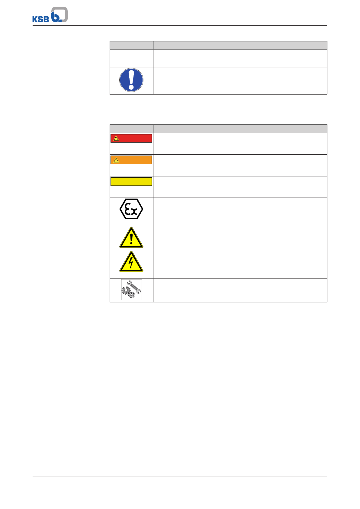
Table3: Definition of safety symbols/markings
Symbol Description
DANGER
This signal word indicates a high-risk hazard which, if not avoided,
will result in death or serious injury.
WARNING
This signal word indicates a medium-risk hazard which, if not
avoided, could result in death or serious injury.
CAUTION
This signal word indicates a hazard which, if not avoided, could
result in damage to the machine and its functions.
Explosion protection
This symbol identifies information about avoiding explosions in
potentially explosive atmospheres in accordance with EU Directive
2014/34/EU (ATEX).
General hazard
In conjunction with one of the signal words this symbol indicates a
hazard which will or could result in death or serious injury.
Electrical hazard
In conjunction with one of the signal words this symbol indicates a
hazard involving electrical voltage and identifies information about
protection against electrical voltage.
Machine damage
In conjunction with the signal word CAUTION this symbol indicates
a hazard for the machine and its functions.
Vitacast / Vitacast Bloc
7 of 80
Page 8

2 Safety
!
DANGER
2 Safety
All the information contained in this section refers to hazardous situations.
In addition to the present general safety information the action-related safety
information given in the other sections must be observed.
2.1 General
This operating manual contains general installation, operating and maintenance
instructions that must be observed to ensure safe operation of the system and
prevent personal injury and damage to property.
The safety information in all sections of this manual must be complied with.
The operating manual must be read and understood by the responsible specialist
personnel/operators prior to installation and commissioning.
The contents of this operating manual must be available to the specialist personnel
at the site at all times.
Information attached directly to the product must always be complied with and kept
in a perfectly legible condition at all times. This applies to, for example:
▪ Arrow indicating the direction of rotation
▪ Markings for connections
▪ Name plate
The operator is responsible for ensuring compliance with all local regulations not
taken into account in this operating manual.
2.2 Intended use
▪ The pump (set) must only be operated in the fields of application and within the
use limits specified in the other applicable documents.
▪ Only operate pumps/pump sets which are in perfect technical condition.
▪ Do not operate the pump (set) in partially assembled condition.
▪ Only use the pump to handle the fluids described in the data sheet or product
literature of the pump model or variant.
▪ Never operate the pump without the fluid to be handled.
▪ Observe the minimum flow rates indicated in the data sheet or product literature
(to prevent overheating, bearing damage, etc).
▪ Observe the minimum flow rate and maximum flow rate indicated in the data
sheet or product literature (to prevent overheating, mechanical seal damage,
cavitation damage, bearing damage, etc).
▪ Do not throttle the flow rate on the suction side of the pump (to prevent
cavitation damage).
▪ Consult the manufacturer about any use or mode of operation not described in
the data sheet or product literature.
2.3 Personnel qualification and training
All personnel involved must be fully qualified to transport, install, operate, maintain
and inspect the machinery this manual refers to.
The responsibilities, competence and supervision of all personnel involved in
transport, installation, operation, maintenance and inspection must be clearly
defined by the operator.
Deficits in knowledge must be rectified by means of training and instruction
provided by sufficiently trained specialist personnel. If required, the operator can
commission the manufacturer/supplier to train the personnel.
Training on the pump (set) must always be supervised by technical specialist
personnel.
8 of 80
Vitacast / Vitacast Bloc
Page 9

2 Safety
2.4 Consequences and risks caused by non-compliance with this manual
▪ Non-compliance with these operating instructions will lead to forfeiture of
warranty cover and of any and all rights to claims for damages.
▪ Non-compliance can, for example, have the following consequences:
– Hazards to persons due to electrical, thermal, mechanical and chemical
effects and explosions
– Failure of important product functions
– Failure of prescribed maintenance and servicing practices
– Hazard to the environment due to leakage of hazardous substances
2.5 Safety awareness
In addition to the safety information contained in this manual and the intended use,
the following safety regulations shall be complied with:
▪ Accident prevention, health regulations and safety regulations
▪ Explosion protection regulations
▪ Safety regulations for handling hazardous substances
▪ Applicable standards, directives and laws
2.6 Safety information for the operator/user
▪ Fit protective equipment (e.g. contact guards) supplied by the operator for hot,
cold or moving parts, and check that the equipment functions properly.
▪ Do not remove any protective equipment (e.g. contact guards) during operation.
▪ Provide the personnel with protective equipment and make sure it is used.
▪ Contain leakages (e.g. at the shaft seal) of hazardous fluids handled (e.g.
explosive, toxic, hot) so as to avoid any danger to persons and the environment.
Adhere to all relevant laws.
▪ Eliminate all electrical hazards. (In this respect refer to the applicable national
safety regulations and/or regulations issued by the local energy supply
companies.)
▪ If shutting down the pump does not increase potential risk, fit an emergency-
stop control device in the immediate vicinity of the pump (set) during pump set
installation.
2.7 Safety information for maintenance, inspection and installation
▪ Modifications or alterations of the pump (set) are only permitted with the
manufacturer's prior consent.
▪ Use only original spare parts or parts/components authorised by the
manufacturer. The use of other parts/components can invalidate any liability of
the manufacturer for resulting damage.
▪ The operator ensures that maintenance, inspection and installation is performed
by authorised, qualified specialist personnel who are thoroughly familiar with
the manual.
▪ Only carry out work on the pump (set) during standstill of the pump.
▪ Only perform work on the pump set when it has been disconnected from the
power supply (de-energised).
▪ The pump (set) must have cooled down to ambient temperature.
▪ Pump pressure must have been released and the pump must have been drained.
Vitacast / Vitacast Bloc
9 of 80
Page 10
2 Safety
!
DANGER
▪ When taking the pump set out of service always adhere to the procedure
described in the manual. (ðSection6.1.6,Page37) (ðSection6.3,Page43)
▪ Decontaminate pumps which handle fluids posing a health hazard.
▪ As soon as the work has been completed, re-install and re-activate any safety-
relevant devices and protective devices. Before returning the product to service,
observe all instructions on commissioning. (ðSection6.1,Page34)
2.8 Unauthorised modes of operation
Never operate the pump (set) outside the limits stated in the data sheet and in this
manual.
The warranty relating to the operating reliability and safety of the supplied pump
(set) is only valid if the equipment is used in accordance with its intended use.
(ðSection2.2,Page8)
2.9 Explosion protection
Always observe the information on explosion protection given in this section when
operating the product in potentially explosive atmospheres.
Only pumps/pump sets marked as explosion-proof and identified as such in the data
sheet may be used in potentially explosive atmospheres.
Special conditions apply to the operation of explosion-proof pump sets to EU
Directive 2014/34/EU (ATEX).
Especially adhere to the sections in this manual marked with the symbol opposite and
the following sections, (ðSection2.9.1,Page10) to (ðSection2.9.4,Page11)
The explosion-proof status of the pump set is only assured if the pump set is used in
accordance with its intended use.
Never operate the pump set outside the limits stated in the data sheet and on the
name plate.
Prevent impermissible modes of operation at all times.
2.9.1 Marking
Pump The marking on the pump refers to the pump part only.
Example of such marking:
II 2 G c TX (EN 13463-1) or II 2G Ex h IIC T5-T1 Gb (ISO 80079-36)
Refer to the individual Temperature Limits table for the temperatures permitted for
the individual pump variants.
The pump complies with the requirements of type of protection constructional safety
"c" to ISO80079-37.
Shaft coupling An EC manufacturer's declaration is required for the shaft coupling; the shaft
coupling must be marked accordingly.
Motor The motor must be considered separately.
2.9.2 Temperature limits
In normal pump operation, the highest temperatures are to be expected on the
surface of the pump casing, at the shaft seal and in the bearing areas.
The surface temperature at the pump casing corresponds to the temperature of the
fluid handled. If the pump is heated in addition, the operator of the system is
responsible for observing the specified temperature class and fluid temperature
(operating temperature).
The table below lists the temperature classes and the resulting theoretical
temperature limits of the fluid handled (a possible temperature rise in the shaft seal
area has already been taken into account).
The temperature class specifies the maximum permissible temperature at the surface
of the pump set during operation.
For the permissible operating temperature of the pump in question refer to the data
sheet.
10 of 80
Vitacast / Vitacast Bloc
Page 11

Motor supplied by the
operator
2 Safety
Table4: Temperature limits
Temperature class to EN 13463-1 or
ISO 80079-36
T1 Temperature limit of the pump
T2 Temperature limit of the pump
T3 130 °C
T4 60 °C
If the pump is to be operated at a higher temperature, if there is no data sheet or if
the pump is part of a pool of pumps, contact KSB for the maximum permissible
operating temperature.
If a pump is supplied without motor (as part of a pool of pumps), the motor specified
in the pump data sheet must meet the following conditions:
▪ The permissible temperature limits at the motor flange and motor shaft must be
higher than the temperatures generated by the pump.
▪ Contact the manufacturer for the actual pump temperatures.
2.9.3 Monitoring equipment
The pump (set) must only be operated within the limits specified in the data sheet
and on the name plate.
If the system operator cannot warrant compliance with these operating limits,
appropriate monitoring devices must be used.
Check whether monitoring equipment is required to ensure that the pump set
functions properly.
Contact KSB for further information about monitoring equipment.
Maximum permissible
fluid temperature
2.9.4 Operating limits
The minimum flows indicated in (ðSection6.2.5.1,Page42) refer to water and
water-like fluids handled. Longer operating periods with these fluids and at the flow
rates indicated will not cause an additional increase in the temperatures at the pump
surface. However, if the physical properties of the fluids handled are different from
water, it is essential to check whether an additional heat build-up may occur and if
the minimum flow rate must therefore be increased. The calculation formula in
(ðSection6.2.5.1,Page42) can be used to check whether additional heat build-up
may lead to a dangerous temperature increase at the pump surface.
Vitacast / Vitacast Bloc
11 of 80
Page 12
3 Transport/Temporary Storage/Disposal
3 Transport/Temporary Storage/Disposal
3.1 Checking the condition upon delivery
1. On transfer of goods, check each packaging unit for damage.
2. In the event of in-transit damage, assess the exact damage, document it and
notify KSB or the supplying dealer and the insurer about the damage in writing
immediately.
3.2 Transport
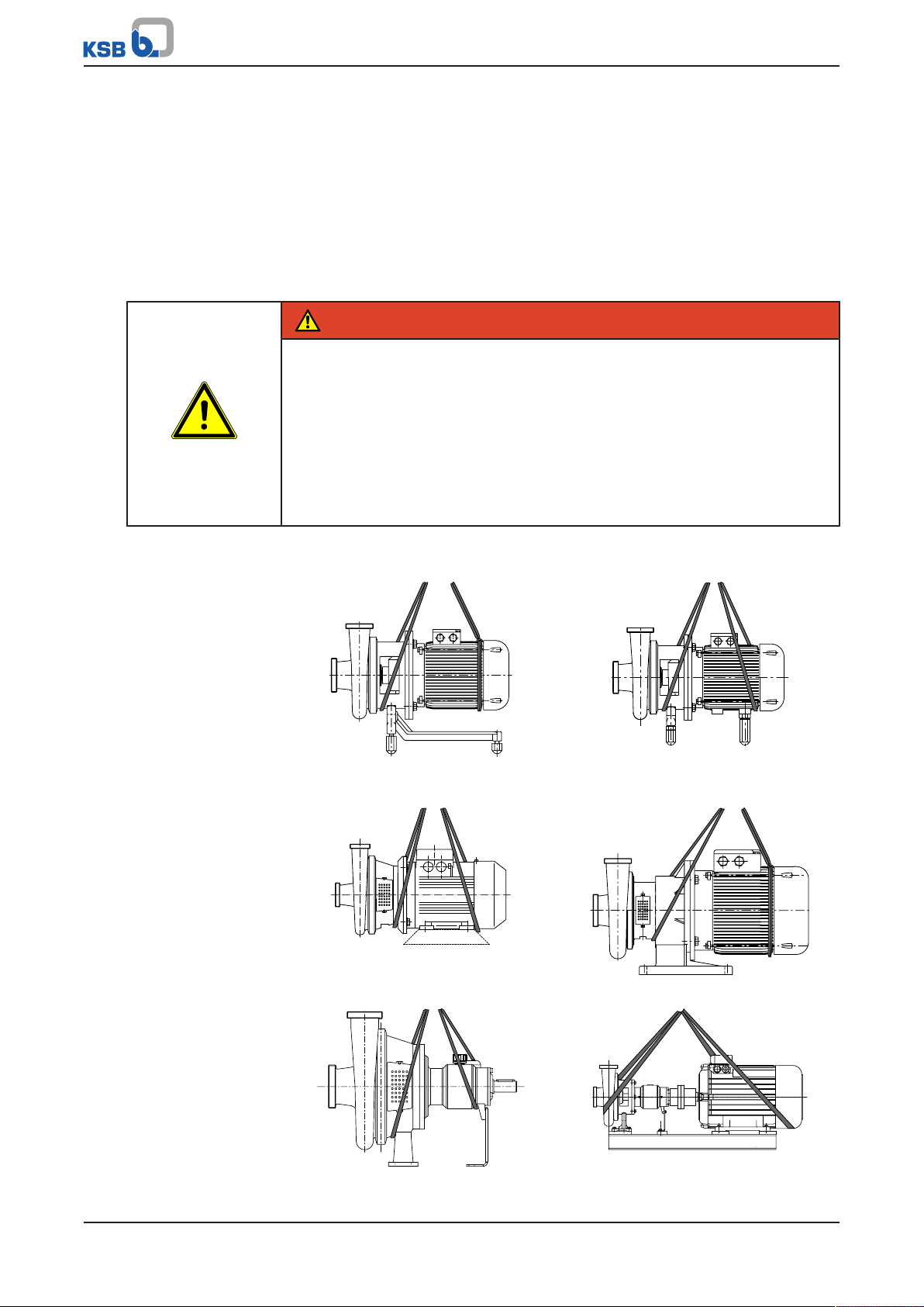
DANGER
The pump (set) could slip out of the suspension arrangement
Danger to life from falling parts!
▷ Always transport the pump (set) in the specified position.
▷ Never attach the suspension arrangement to the free shaft end or the motor
eyebolt.
▷ Observe the information about weights, centre of gravity and fastening points.
▷ Observe the applicable local accident prevention regulations.
▷ Use suitable, permitted lifting accessories, e.g. self-tightening lifting tongs.
Vitacast-Bloc
Vitacast
1. If a motor shroud is fitted, remove it before transporting the pump set.
2. To transport the pump/pump set suspend it from the lifting tackle as shown.
Transporting installation type K
3-point ball feet
Transporting installation type M Transporting installation type L
Transporting installation type K
4-point ball feet
12 of 80
Transporting the Fig.0 (bare shaft) pump Transporting the pump set with baseplate
Vitacast / Vitacast Bloc
Page 13
3 Transport/Temporary Storage/Disposal
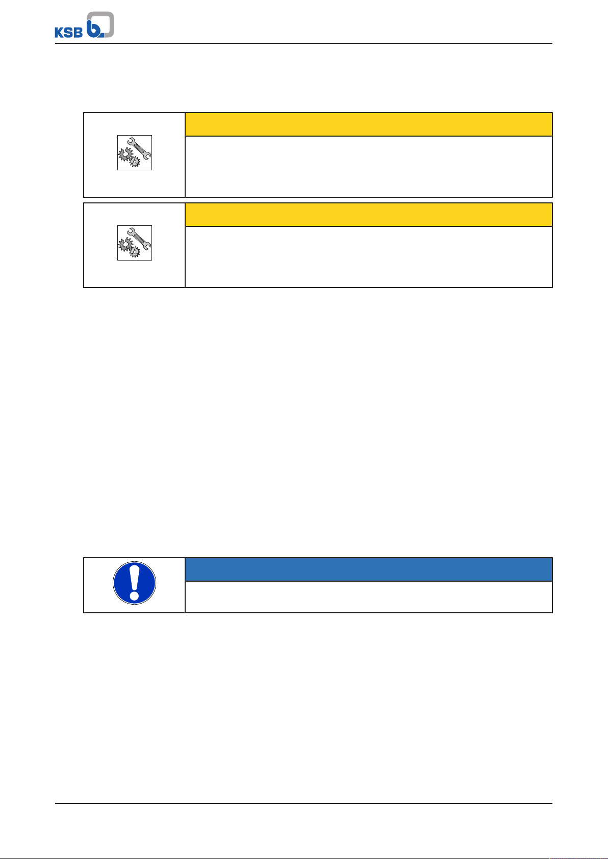
3.3 Storage/preservation
If commissioning is to take place some time after delivery, we recommend that the
following measures be taken for pump (set) storage.
CAUTION
Damage during storage due to humidity, dirt or vermin
Corrosion/contamination of the pump (set)!
▷ For outdoor storage cover the pump (set) or the packaged pump (set) and
accessories with waterproof material.
CAUTION
Wet, contaminated or damaged openings and connections
Leakage or damage to the pump!
▷ Clean and cover pump openings and connections as required prior to putting
the pump into storage.
Store the pump (set) in a dry, protected room where the atmospheric humidity is as
constant as possible.
Rotate the shaft by hand once a month, e.g. via the motor fan.
If properly stored indoors, the pump set is protected for a maximum of 12 months.
New pumps/pump sets are supplied by our factory duly prepared for storage.
For storing a pump (set) which has already been operated, the shutdown measures
must be adhered to. (ðSection6.3.1,Page43)
3.4 Return to supplier
1. Drain the pump as per operating instructions. (ðSection7.3,Page51)
2. Flush and clean the pump, particularly if it has been used for handling noxious,
explosive, hot or other hazardous fluids.
3. If the pump has handled fluids whose residues could lead to corrosion damage
in the presence of atmospheric humidity or could ignite upon contact with
oxygen also neutralise the pump and blow through with anhydrous inert gas to
ensure drying.
4. Always complete and enclose a certificate of decontamination when returning
the pump.
Indicate any safety measures and decontamination measures taken.
(ðSection11,Page77)
NOTE
If required, a blank certificate of decontamination can be downloaded from the
following web site: www.ksb.com/certificate_of_decontamination
Vitacast / Vitacast Bloc
13 of 80
Page 14

3 Transport/Temporary Storage/Disposal
3.5 Disposal
WARNING
Fluids handled, consumables and supplies which are hot and/or pose a health
hazard
Hazard to persons and the environment!
▷ Collect and properly dispose of flushing fluid and any fluid residues.
▷ Wear safety clothing and a protective mask if required.
▷ Observe all legal regulations on the disposal of fluids posing a health hazard.
1. Dismantle the pump (set).
Collect greases and other lubricants during dismantling.
2. Separate and sort the pump materials, e.g. by:
- Metals
- Plastics
- Electronic waste
- Greases and other lubricants
3. Dispose of materials in accordance with local regulations or in another
controlled manner.
14 of 80
Vitacast / Vitacast Bloc
Page 15
4 Description of the Pump (Set)
4 Description of the Pump (Set)
4.1 General description
▪ Hygienic pump
Pump for handling fluids which are not chemically aggressive, are free from solids
and do not require hermetic sealing.
Hygienic centrifugal pump for the food and beverage industry and the
pharmaceutical industry
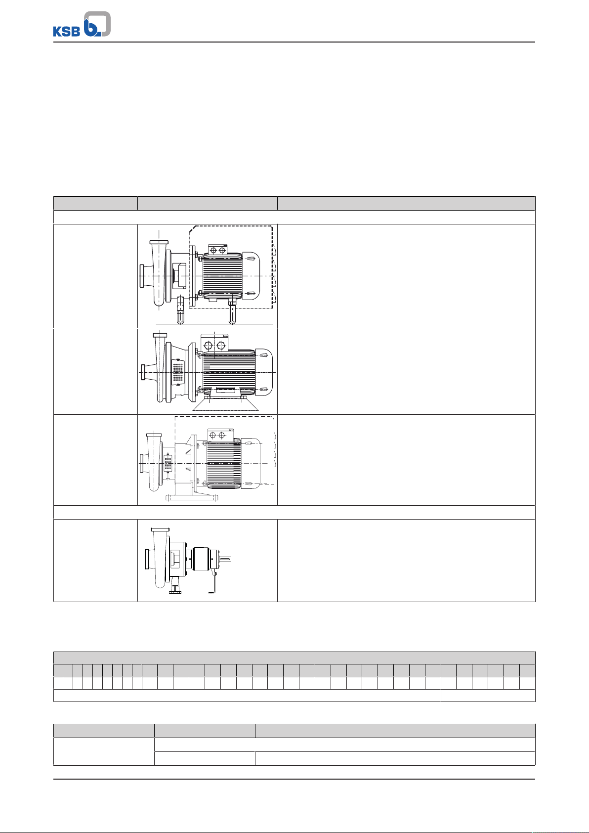
Table5: Installation type
Installation type Illustration Description
Vitacast Bloc
K Horizontal installation, close-coupled pump set
▪ Axial suction nozzle, radial discharge nozzle, adjustable
through 360°
▪ Mounted on 3-point ball feet up to a drive rating of
4kW.
▪ Mounted on 4-point ball feet for drive ratings from 5.5
to 22kW.
M Horizontal installation, close-coupled pump set
▪ Axial suction nozzle, radial discharge nozzle, adjustable
through 360°
▪ Mounted on a motor foot for drive ratings from 0.33 to
22kW.
L Horizontal installation, close-coupled pump set
▪ Axial suction nozzle, radial discharge nozzle, adjustable
through 360°
▪ Connected to the motor via a bearing pedestal for drive
ratings of 30kW.
Vitacast
Fig. 0 (bare shaft) Horizontal installation, pump with bearing bracket
▪ Mounted on a baseplate
▪ Pump shaft and motor shaft connected via a coupling:
– Drive rating > 30 kW: standard
– Drive rating < 30 kW: option
4.2 Designation
Table6: Designation example
Position
1 2 3 4 5 6 7 8 9 10 11 12 13 14 15 16 17 18 19 20 21 22 23 24 25 26 27 28 29 30 31 32 33 34
V A I 0 4 0 - 0 3 2 - 1 4 5 0 4 0 2 G B T 8 1 A E C C S X O A
See name plate and data sheet See data sheet
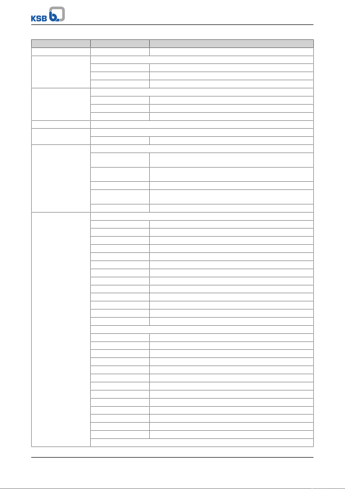
Table7: Designation key
Position Code Description
1-4 Pump type
VA Vitacast
Vitacast / Vitacast Bloc
15 of 80
Page 16
4 Description of the Pump (Set)
Position Code Description
1-4 VAI Vitacast Inducer
5-16 Size, e.g.
040 Nominal suction nozzle diameter [mm]
032 Nominal discharge nozzle diameter [mm]
145 Impeller diameter [mm]
17-19 Motor rating PN [kW]
007 0,70
... ...
550 55,00
20 Number of motor poles
21 Scope of supply
G Baseplate
22-23 Shaft seal type
B Single mechanical seal, internal, dead-end arrangement, without
flushing
BQ Single mechanical seal, internal, dead-end arrangement, external
flushing (quench)
DB Double mechanical seal in back-to-back arrangement
I Single mechanical seal, internal, dead-end arrangement, internal
circulation
J Single mechanical seal, external, without flushing
24-26 Seal code, single mechanical seal, internal
T00 GCEGG
T18 U3U3VGG
T19 U3U3EGG
T64 U3Q1EGG
T66 Q1Q1M3GG
T68 U3Q1VGG
T69 BQ1M3GG
T80 BQ1VGG
T81 Q1Q1VGG
T82 BQ1EGG
T83 Q1Q1EGG
T84 Q1U3EGG
T85 Q1U3VGG
Seal code, single mechanical seal, internal, with encapsulated spring
H0D GCVGG
H1 Q1CEGG
H1D Q1CVGG
H2 Q1U3EGG
H2D Q1U3VGG
H3 Q1Q1EGG
H3D Q1Q1VGG
H4 U3U3EGG
H5 Q2Q2EGG**
H7 U2U2VGG*
H8 U3U3VGG
H9 BQ1VGG*
HA U3U3EGG
Seal code, single mechanical seal, external
16 of 80
Vitacast / Vitacast Bloc
Page 17
4 Description of the Pump (Set)
Position Code Description
24-26 Y06 U3U3EGG
Y07 BU3EGG
Seal code, double mechanical seal in back-to-back arrangement
Q80 BQ1VGG
BGVGG
Q81 Q1Q1VGG
BGVGG
Q82 BQ1EGG
BGEGG
Q83 Q1Q1EGG
BGEGG
Q84 Q1U3EGG
BGEGG
Q85 Q1U3VGG
BGVGG
27 Pipe connection
A Flange APV
B Threaded connection DIN 11864-1A
C Flange DIN 11864-2A
D Clamped connection DIN 11864-3A
E Threaded connection DIN 11853
F Threaded connection RJT
G Flange Varivent
I Threaded connection ISO 2853 (IDF)
L Flange EN 1092-1
M Threaded connection DIN 11851 (hygienic pipe union)
S Threaded connection SMS
T Clamped connection DIN 32676-A
U Clamped connection DIN32676-C (Tri-Clamp)
V Clamped connection ISO 2852
Z Flange ANSI B16.5 Class 150
28 O-ring material (casing/impeller)
E EPDM
K Kalrez
M FEP (encapsulated)
T PTFE
V FPM
29 Pump casing material
C Stainless steel 1.4409
D Super duplex stainless steel 1.4469/ 1.4410
X Hastelloy C276 2.4819
30 Impeller material
C Stainless steel 1.4409
D Super duplex stainless steel 1.4469/ 1.4410
X Hastelloy C276 2.4819
31 Motor shroud
O Without shroud
S With shroud
32 Design
Vitacast / Vitacast Bloc
17 of 80
Page 18
4 Description of the Pump (Set)
Position Code Description
32
2)
Standard
X Non-standard (BT3D, BT3), including ATEX
33 Draining facility
D Casing drain with plug
O No drain
P Casing drain via piping
V Casing drain via valve
34 Generation
A Vitacast
4.3 Designation
Table8: Designation example
Position
1 2 3 4 5 6 7 8 9 10 11 12 13 14 15 16 17 18 19 20 21 22 23 24 25 26 27 28 29 30 31 32 33 34
V A B 0 3 2 - 0 2 5 - 1 4 5 0 4 0 2 K B T 8 1 M E C C S X O A
See name plate and data sheet See data sheet
Table9: Designation key
Position Code Description
1-4 Pump type
VAB Vitacast Bloc
VABI Vitacast Bloc Inducer
5-16 Size, e.g.
040 Nominal suction nozzle diameter [mm]
025 Nominal discharge nozzle diameter [mm]
200 Nominal impeller diameter [mm]
17-19 Motor rating PN [kW]
007 0,7
... ...
550 55,00
20 Number of motor poles
21 Scope of supply
K Ball feet
L Bearing bracket
M Motor foot
T Round base feet
V Trolley
22-23 Shaft seal type
B Single mechanical seal, internal, dead-end arrangement, without
flushing
BQ Single mechanical seal, internal, dead-end arrangement, external
flushing (quench)
DB Double mechanical seal, external, in back-to-back arrangement
I Single mechanical seal, internal, dead-end arrangement, internal
circulation
J Single mechanical seal, external, without flushing
24-26 Seal code, single mechanical seal, internal
T00 GCEGG
2) Blank
18 of 80
Vitacast / Vitacast Bloc
Page 19
4 Description of the Pump (Set)
Position Code Description
24-26 T18 U3U3VGG
T19 U3U3EGG
T64 U3Q1EGG
T66 Q1Q1M3GG
T68 U3Q1VGG
T69 BQ1M3GG
T80 BQ1VGG
T81 Q1Q1VGG
T82 BQ1EGG
T83 Q1Q1EGG
T84 Q1U3EGG
T85 Q1U3VGG
Seal code, single mechanical seal, internal, with encapsulated spring
H0D GCVGG
H1 Q1CEGG
H1D Q1CVGG
H2 Q1U3EGG
H2D Q1U3VGG
H3 Q1Q1EGG
H3D Q1Q1VGG
H4 U3U3EGG
H5 Q2Q2EGG**
HA U3U3EGG
H7 U2U2VGG*
H8 U3U3VGG
H9 BQ1VGG*
Seal code, single mechanical seal, external
Y06 U3U3EGG
Y07 BU3EGG
Seal code, double mechanical seal, external, back-to-back arrangement
Q70 GCEGG
GBEGG
Q71 U3CEGG
GCEGG
Q72 U3U3EGG
U3BGG
Q74 U3U3VGG
BU3VGG
Q78 U3U3VGG
U3U3VGG
Q79 U3U3TGG
U3CTGG
27 Pipe connection
A Flange APV
B Threaded connection DIN 11864-1A
C Flange DIN 11864-2A
D Clamped connection DIN 11864-3A
E Threaded connection DIN 11853
F Threaded connection RJT
Vitacast / Vitacast Bloc
19 of 80
Page 20

4 Description of the Pump (Set)
Position Code Description
27 G Flange Varivent
I Threaded connection ISO 2853 (IDF)
L Flange EN 1092-1
M Threaded connection DIN 11851 (hygienic pipe union)
S Threaded connection SMS
T Clamped connection DIN 32676-A
U Clamped connection DIN32676-C (Tri Clamp)
V Clamped connection ISO 2852
Z Flange ANSI B16.5 Class 150
28 O-ring material (casing/impeller)
E EPDM
K Kalrez
M FEP (encapsulated)
P PTFE
V FPM
29 Pump casing material
C Stainless steel 1.4409
D Super duplex stainless steel 1.4469/ 1.4410
X Hastelloy C276 2.4819
30 Impeller material
C Stainless steel 1.4409
D Super duplex stainless steel 1.4469/ 1.4410
X Hastelloy C276 2.4819
31 Motor shroud
O Without shroud
S With shroud
32 Design
3)
Standard
X Non-standard (BT3D, BT3), including ATEX
33 Drain
D Casing drain with plug
O No drain
P Casing drain via pipeline
V Casing drain via valve
34 Generation
A Vitacast Bloc
3) Blank
20 of 80
Vitacast / Vitacast Bloc
Page 21

4 Description of the Pump (Set)
VAB 032-025-145 0402KB T81ME
E-Nr
Nr
H 20 mQ 8 m
3
/h
Jahr 2016
n 2900 1/min
1
2
4
3
6
7
5
Johann-Klein-Straße 9
Deutschland
67227 Frankenthal
KSB SE & Co. KGaA
4.4 Name plate
Fig.1: Name plate of a Vitacast-Bloc (example)
1 Type series, size and version 2 KSB order number
3 Manufacturer's No. 4 Flow rate
5 Head 6 Speed
7 Year of construction
4.5 Design details
Design
▪ Hygienic centrifugal pump
▪ Single-stage
▪ Close-coupled design and long-coupled design
▪ Non-self-priming
▪ Wetted parts made of stainless steel 1.4404/1.4409 (AISI316L/CF3M)
Pump casing
▪ Volute casing
Impeller type
▪ Open multi-vane impeller
Bearings
▪ Grease-packed deep groove ball bearing
▪ Bearing in oil bath
Shaft seal
▪ Single mechanical seal to EN12756
– Seal typeT5): pump-end seal with non-encapsulated spring surrounded by
fluid handled, uni-directional
– Seal typeH6): pump-end seal with encapsulated spring, polished surface, bi-
directional
– Seal type Y: external seal
– Double mechanical seal to EN12756
– Seal type Q: back-to-back arrangement (pressurised barrier fluid)
4)
4) Vitacast only
5) Hygienic design
6) Sterile design
Vitacast / Vitacast Bloc
21 of 80
Page 22

4 Description of the Pump (Set)
Drive
Standard design:
▪ KSB surface-cooled IEC three-phase current squirrel-cage motor
▪ 50Hz winding, 220-240V/ 380-420V ≤2.20kW
▪ 50Hz winding, 380-420V/ 660-725V ≥3.00kW
▪ 60Hz winding, 440-480V ≤2.60kW
▪ 60Hz winding, 440-480V ≥3.60kW
▪ Type of construction IMV1 ≤4.00kW
▪ Type of construction IMV15 ≥5.50kW
▪ Enclosure IP55
▪ Duty cycle: continuous duty S1
▪ Thermal class F with temperature sensor, 3 PTC thermistors
Explosion-proof version:
▪ KSB surface-cooled IEC three-phase current squirrel-cage motor
▪ 50Hz winding, 220-240V/ 380-420V ≤1.85kW
▪ 50Hz winding, 380-420V/ 660-725V ≥2.50kW
▪ Type of construction IMV1 ≤3.30kW
▪ Type of construction IMV15 ≥4.60kW
▪ Enclosure IP55 or IP54
▪ Duty cycle: continuous duty S1
▪ Type of protection EEx e II
▪ Temperature class T3
Automation
Automation options:
▪ PumpDrive
▪ PumpMeter
Connections
▪ Axial suction nozzle, tangential discharge nozzle
▪ Adjustable through 360°
Types of connection:
▪ Threaded connection to DIN11851 (hygienic pipe union)
▪ Threaded connection to DIN11853
▪ Threaded connection to DIN11864-1-GS-A
▪ Threaded connection to SMS standard
▪ Threaded connection to ISO2853 (IDF)
▪ Threaded connection to RJT standard
▪ Clamped connection to DIN32676-C (Tri-Clamp/Tri-Clover fitting)
▪ Clamped connection to DIN11864-3-NKS-A
▪ Clamped connection to DIN32676-A
▪ Clamped connection to ISO2852
▪ Flange to EN1092-1
▪ Flange to DIN11864-2-NF-A
▪ Flange to ANSI B16.5 Class 150
▪ APV flange
▪ Varivent flange
▪ Other connection types on request
22 of 80
Vitacast / Vitacast Bloc
Page 23
4 Description of the Pump (Set)
7
8
9 10 11
12
1
2
3
4
5 6
4.6 Configuration and function
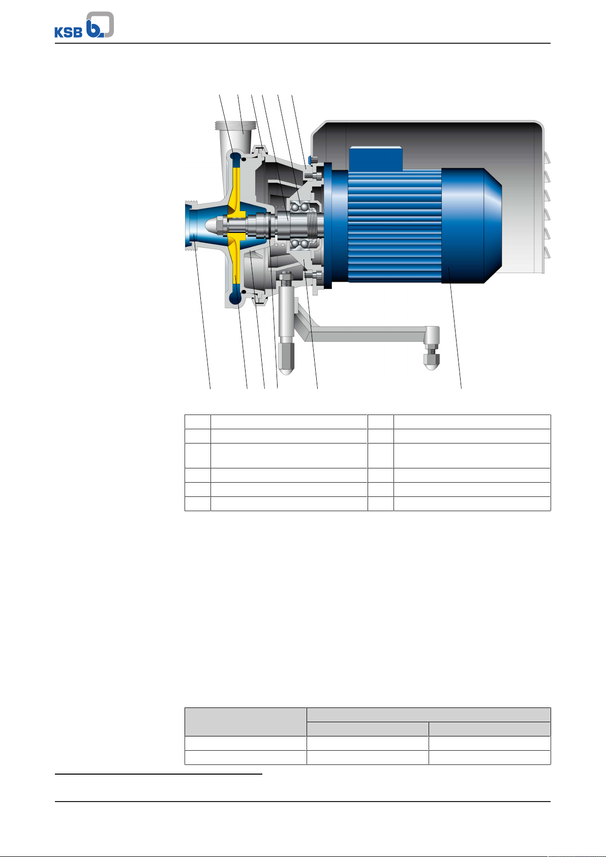
Fig.2: Sectional drawing of a Vitacast Bloc
1 Volute channel 2 Discharge nozzle
3 Clamping piece 4 Pump shaft
5 Rolling element bearing for pump
shaft
7 Suction nozzle 8 Impeller
9 Casing cover 10 Shaft seal
11 Bearing assembly 12 Drive
Design The pump is designed with an axial fluid inlet and a radial outlet. The hydraulic
system is rigidly connected to the motor via a stub shaft.
Function The fluid enters the pump via the suction nozzle (7) and is accelerated outward in a
radial flow by the rotating impeller (8). In the flow passage of the pump casing (1)
the kinetic energy is converted into pressure energy. The fluid is pumped to the
discharge nozzle (2), where it leaves the pump. At the rear side of the impeller, the
shaft (4) enters the hydraulic system via the casing cover (9). The shaft passage
through the cover is sealed to atmosphere with a dynamic shaft seal (10). The pump
shaft runs in a rolling element bearing (5), which is supported by a bearing assembly
(11). The motor shaft is inserted into the pump shaft (stub shaft). The drive (12) is
connected to the pump via the drive lantern (6).
Sealing The pump is sealed by a mechanical seal.
6 Drive lantern
4.7 Noise characteristics
Table10: Surface sound pressure level LpA [dB]
Size Pump set
1450 rpm 2900 rpm
032-025-145 < 70 71 - 75
032-025-175 < 70 71 - 75
7)
7) Measured at a distance of 1 metre, 1.6 metres above the installation surface
Vitacast / Vitacast Bloc
23 of 80
Page 24
4 Description of the Pump (Set)
Size Pump set
1450 rpm 2900 rpm
040-032-110 < 70 71 - 75
040-032-145 < 70 71 - 75
040-032-175 < 70 71 - 75
040-032-210 < 70 76 - 80
050-032-260 < 70 050-040-145 < 70 76 - 80
050-040-175 < 70 76 - 80
050-040-210 < 70 76 - 80
050-040-260 < 70 065-050-145 < 70 76 - 80
065-050-175 < 70 76 - 80
065-050-210 < 70 76 - 80
065-050-260 < 70 81 - 85
080-065-145 < 70 81 - 85
080-065-175 < 70 81 - 85
080-065-210 < 70 86 - 90
080-065-260 71 - 75 86 - 90
100-080-175 71 - 75 81 - 85
100-080-210 71 - 75 86 - 90
100-080-260 71 - 75 86 - 90
100-080-310 71 - 75 125-100-210 71 - 75 86 - 90
125-100-310 71 - 75 150-125-350 71 - 75 200-150-350 71 - 75 -
4.8 Scope of supply
Depending on the model, the following items are included in the scope of supply:
▪ Pump
▪ Drive
▪ Frequency inverter
▪ Motor shroud
▪ Pump foot or foot base (e.g. 3-point ball feet)
▪ Trolley with switch and power cable
4.9 Dimensions and weights
For dimensions and weights please refer to the general arrangement drawing/outline
drawing of the pump/pump set.
24 of 80
Vitacast / Vitacast Bloc
Page 25

5 Installation at Site
5 Installation at Site
5.1 Checks to be carried out prior to installation
Place of installation
WARNING
Installation on mounting surface which is unsecured and cannot support the load
Personal injury and damage to property!
▷ Use a concrete of compressive strength class C12/15 which meets the
requirements of exposure class XC1 to EN206-1.
▷ The mounting surface must be set, flat, and level.
▷ Observe the weights indicated.
1. Check the structural requirements.
All structural work required must have been prepared in accordance with the
dimensions stated in the outline drawing/general arrangement drawing.
5.2 Installing the pump set
DANGER
Excessive temperatures due to improper installation
Explosion hazard!
▷ Install the pump in a horizontal position to ensure self-venting of the pump.
DANGER
Static charging due to insufficient potential equalisation
Explosion hazard!
▷ Make sure that the connection between pump and baseplate is electrically
conductive.
CAUTION
Ingress of leakage into the motor
Damage to the pump!
▷ Never install the pump set with the "motor below".
NOTE
For pump sets with a motor rating >30kW installation without a foundation is not
recommended.
Always install the pump set in a horizontal position.
Table11: Installation type
Motor size Installation type
71 ... 180 Ball feet
71 ... 180 Motor foot
Vitacast / Vitacast Bloc
25 of 80
Page 26

5 Installation at Site
L
1
32
Motor size Installation type
200 Bearing pedestal
112 ... 280 Baseplate
1. Position the pump set on the foundation. Fasten it depending on the
installation type.
2. Place a spirit level on the discharge nozzle to align the pump set.
5.2.1 Installation on a foundation
Fig.3: Fitting the shims
L Bolt-to-bolt distance 1 Shim
2 Shim if (L) > 800mm 3 Foundation bolt
ü The foundation has the required strength and characteristics.
ü The foundation has been prepared in accordance with the dimensions given in
the outline drawing/general arrangement drawing.
1. Position the pump set on the foundation and level it with the help of a spirit
level placed on the shaft and discharge nozzle.
Permissible deviation: 0.2mm/m
2. Use shims (1) for height compensation, if necessary.
Always fit shims, if any, immediately to the left and right of the foundation
bolts (3) between the baseplate/foundation frame and the foundation.
For a bolt-to-bolt distance (L) >800mm fit additional shims (2) halfway between
the bolt holes.
All shims must lie perfectly flush.
3. Insert the foundation bolts (3) into the holes provided.
4. Use concrete to set the foundation bolts (3) into the foundation.
5. Wait until the concrete has set firmly, then level the baseplate.
6. Tighten the foundation bolts (3) evenly and firmly.
7. Grout the baseplate using low-shrinkage concrete with a standard particle size
and a water/cement ratio of ≤ 0.5.
Produce flowability with the help of a solvent.
Perform secondary treatment of the concrete to EN206.
26 of 80
NOTE
For low-noise operation the pump set can be mounted on vibration dampers upon
confirmation by the manufacturer. In this case, only fasten the flexible elements at
the baseplate after the piping has been connected.
NOTE
Expansion joints can be fitted between the pump and the suction/discharge line.
Vitacast / Vitacast Bloc
Page 27

5 Installation at Site
4
1
2
3
5.2.2 Installation without foundation
Fig.4: Adjusting the levelling elements
1, 3 Locknut 2 Adjusting nut
4 Machine mount
ü The installation surface has the required strength and characteristics.
1. Position the pump set on the machine mounts (4) and align it with the help of a
spirit level (on the shaft/discharge nozzle).
2. To adjust any differences in height, loosen the locknuts (1, 3) of the machine
mounts (4).
3. Turn the adjusting nut (2) until any differences in height have been
compensated.
4. Re-tighten the locknuts (1, 3) at the machine mounts (4).
5.3 Piping
5.3.1 Connecting the piping
DANGER
Impermissible loads acting on the pump nozzles
Danger to life from leakage of hot, toxic, corrosive or flammable fluids!
▷ Do not use the pump as an anchorage point for the piping.
▷ Anchor the pipes in close proximity to the pump and connect them properly
without transmitting any stresses or strains.
▷ Take appropriate measures to compensate for thermal expansion of the piping.
CAUTION
Incorrect earthing during welding work at the piping
Destruction of rolling element bearings (pitting effect)!
▷ Never earth the electric welding equipment on the pump or baseplate.
▷ Prevent current flowing through the rolling element bearings.
Vitacast / Vitacast Bloc
27 of 80
Page 28

5 Installation at Site
1
2
NOTE
Installing check and shut-off elements in the system is recommended, depending on
the type of plant and pump. However, such elements must not obstruct proper
drainage or hinder disassembly of the pump.
ü Suction lift lines have been laid with a rising slope, suction head lines with a
downward slope towards the pump.
ü A flow stabilisation section having a length equivalent to at least twice the
diameter of the suction flange has been provided upstream of the suction flange.
ü The nominal diameters of the pipelines are equal to or greater than the nominal
diameters of the pump nozzles.
ü Adapters to larger nominal diameters are designed with a diffuser angle of
approx. 8° to avoid excessive pressure losses.
ü The pipelines have been anchored in close proximity to the pump and connected
without transmitting any stresses or strains.
1. Thoroughly clean, flush and blow through all vessels, pipelines and connections
(especially of new installations).
2. Before installing the pump in the piping, remove the flange covers on the
suction and discharge nozzles of the pump.
CAUTION
Welding beads, scale and other impurities in the piping
Damage to the pump!
▷ Remove any impurities from the piping.
▷ If necessary, install a filter.
▷ Observe the information in (ðSection7.2.2.3,Page48) .
3. Check that the inside of the pump is free from any foreign objects. Remove any
foreign objects.
4. If required, install a filter in the piping (see drawing: Filter in the piping).
Fig.5: Filter in the piping
1 Differential pressure gauge 2 Filter
28 of 80
NOTE
Use a filter with laid-in wire mesh (mesh width 0.5mm, wire diameter 0.25mm) of
corrosion-resistant material.
Use a filter with a filter area three times the cross-section of the piping.
Conical filters have proved suitable.
5. Connect the pump nozzles to the piping.
Vitacast / Vitacast Bloc
Page 29

5 Installation at Site
CAUTION
Aggressive flushing liquid and pickling agent
Damage to the pump!
▷ Match the cleaning operation mode and duration of flushing and pickling to
the casing materials and seal materials used.
5.3.2 Permissible forces and moments at the pump nozzles
No piping-induced forces and moments (from warped pipelines or thermal
expansion, for example) must act on the pump.
5.3.3 Auxiliary connections
DANGER
Risk of potentially explosive atmosphere by mixing of incompatible fluids in the
auxiliary piping
Risk of burns!
Explosion hazard!
▷ Make sure that the barrier fluid or quench liquid are compatible with the fluid
handled.
CAUTION
Failure to use or incorrect use of auxiliary connections (flushing liquid)
Malfunction of the pump!
▷ Use and install any auxiliary connections in such a way that a proper flow is
ensured.
If a shaft seal with flush connection is used, fit the flushing liquid reservoir in the
immediate vicinity of the pump set approximately 1metre above the pump
centreline. Fluid circulation is ensured by thermosyphon effect or forced circulation.
When mounting the fittings comply with the instructions provided by the fitting
manufacturers.
NOTE
The flushing liquid feed line must be laid with a continuously rising slope towards
the flushing liquid reservoir.
Make sure that the flushing liquid (if any) circulates properly also before starting up
and after switching off the pump (until the pump set comes to a complete stop).
5.4 Enclosure/insulation
DANGER
Risk of potentially explosive atmosphere due to insufficient venting
Explosion hazard!
▷ Make sure the space between the casing cover/discharge cover and the bearing
cover is sufficiently vented.
▷ Never close or cover the perforation of the bearing bracket guards (e.g. by
insulation).
Vitacast / Vitacast Bloc
29 of 80
Page 30

5 Installation at Site
B
A
A
B
a) b)
B
B
A
A
1
1
2
21
1
WARNING
The volute casing and casing/discharge cover take on the same temperature as the
fluid handled
Risk of burns!
▷ Insulate the volute casing.
▷ Fit protective equipment.
CAUTION
Heat build-up in the bearing bracket
Damage to the bearing!
▷ Never insulate the bearing bracket, bearing bracket lantern and casing cover.
5.5 Checking the coupling alignment
DANGER
Inadmissible temperatures at the coupling or bearings due to misalignment of the
coupling
Explosion hazard!
Risk of burns!
▷ Make sure that the coupling is correctly aligned at all times.
CAUTION
Misalignment of pump and motor shafts
Damage to pump, motor and coupling!
▷ Always check the coupling after the pump has been installed and connected to
the piping.
▷ Also check the coupling of pump sets supplied with pump and motor mounted
on the same baseplate.
Fig.6: Checking the coupling alignment: Coupling without spacer sleeve (a) or Coupling with spacer sleeve (b)
1 Straight-edge 2 Gauge
ü The coupling guard and its footboard, if any, have been removed.
1. Loosen the support foot and re-tighten it without transmitting any stresses and
strains.
2. Place the straight-edge axially on both coupling halves.
30 of 80
Vitacast / Vitacast Bloc
Page 31

5 Installation at Site
3. Leave the straight-edge in this position and turn the coupling by hand.
The coupling is aligned correctly if the distances A and B to the respective shafts
are the same at all points around the circumference.
The radial and axial deviation between the two coupling halves must not exceed
0.1 mm, during standstill as well as at operating temperature and under inlet
pressure.
4. Check the distance (dimension see general arrangement drawing) between the
two coupling halves around the circumference.
The coupling is correctly aligned if the distance between the two coupling
halves is the same at all points around the circumference.
The radial and axial deviation between the two coupling halves must not exceed
0.1 mm, during standstill as well as at operating temperature and under inlet
pressure.
5. If alignment is correct, re-install the coupling guard and its footboard, if any.
Checking the coupling alignment with a laser tool
Coupling alignment may also be checked with a laser tool. Observe the
documentation provided by the manufacturer of the measuring instrument.
5.6 Electrical connection
DANGER
Electrical connection work by unqualified personnel
Risk of fatal injury due to electric shock!
▷ Always have the electrical connections installed by a trained and qualified
electrician.
▷ Observe regulations IEC 60364 and, for explosion-proof models, EN60079.
WARNING
Incorrect connection to the mains
Damage to the mains network, short circuit!
▷ Observe the technical specifications of the local energy supply companies.
1. Check the available mains voltage against the data on the motor data sheet.
2. Select an appropriate starting method.
NOTE
A motor protection device is recommended.
5.6.1 Setting the time relay
CAUTION
Switchover between star and delta on three-phase motors with star-delta starting
takes too long.
Damage to the pump (set)!
▷ Keep switch-over intervals between star and delta as short as possible.
Table12: Time relay settings for star-delta starting:
Motor rating Y time to be set
[kW] [s]
≤ 30 < 3
> 30 < 5
Vitacast / Vitacast Bloc
31 of 80
Page 32

5 Installation at Site
5.6.2 Connecting the motor
NOTE
In compliance with IEC 60034-8, three-phase motors are always wired for clockwise
rotation (looking at the motor shaft stub).
The pump's direction of rotation is indicated by an arrow on the pump.
1. Match the motor's direction of rotation to that of the pump.
2. Observe the manufacturer's product literature supplied with the motor.
5.6.3 Earthing
DANGER
Electrostatic charging
Explosion hazard!
Fire hazard!
Damage to the pump set!
▷ Connect the PE conductor to the earthing terminal provided.
5.7 Checking the direction of rotation
DANGER
Temperature increase resulting from contact between rotating and stationary
components
Explosion hazard!
Damage to the pump set!
▷ Never check the direction of rotation by starting up the unfilled pump set.
▷ Separate the pump from the motor to check the direction of rotation.
WARNING
Hands inside the pump casing
Risk of injuries, damage to the pump!
▷ Always disconnect the pump set from the power supply and secure it against
unintentional start-up before inserting your hands or other objects into the
pump.
CAUTION
Incorrect direction of rotation with non-reversible mechanical seal
Damage to the mechanical seal and leakage!
▷ Separate the pump from the motor to check the direction of rotation.
32 of 80
CAUTION
Drive and pump running in the wrong direction of rotation
Damage to the pump!
▷ Refer to the arrow indicating the direction of rotation on the pump.
▷ Check the direction of rotation. If required, check the electrical connection and
correct the direction of rotation.
Vitacast / Vitacast Bloc
Page 33

5 Installation at Site
The correct direction of rotation of motor and pump is clockwise (seen from the drive
end).
1. Undo and store screws 900.1, if any.
2. Remove motor shroud 683.
3. Start the drive and stop it again immediately to determine the drive's direction
of rotation.
4. Check the direction of rotation.
The motor's direction of rotation must match the arrow indicating the direction
of rotation on the pump.
5. If the motor is running in the wrong direction of rotation, check the electrical
connection of the motor and the control system, if any.
6. Fasten motor shroud 683 with screws 900.1.
Vitacast / Vitacast Bloc
33 of 80
Page 34

6 Commissioning/Start-up/Shutdown
6 Commissioning/Start-up/Shutdown
6.1 Commissioning/Start-up
6.1.1 Prerequisites for commissioning/start-up
Before commissioning/starting up the pump set, make sure that the following
conditions are met:
▪ The quality of the concrete foundation complies with the regulations.
▪ The pump set has been installed and aligned in accordance with the tolerances
specified.
▪ The pump set has been properly connected to the power supply and is equipped
with all protection devices.
▪ The pump has been primed with the fluid to be handled. The pump has been
vented. (ðSection6.1.3,Page35)
▪ The direction of rotation has been checked.
▪ All auxiliary connections required are connected and operational.
▪ The lubricants have been checked.
▪ The lock washers, if any, have been removed from the shaft groove.
▪ The pump (set) has been installed and connected as described in this manual.
▪ After prolonged shutdown of the pump (set), the activities required for returning
the equipment to service have been carried out.
Vitacast-Bloc
Vitacast
6.1.2 Filling in lubricants
Grease-lubricated bearings
Grease-lubricated bearings have been packed with grease.
Oil-lubricated bearings
Fill the bearing bracket and constant level oiler with lubricating oil.
Oil quality see (ðSection7.2.3.1.2,Page49)
Oil quantity see (ðSection7.2.3.1.3,Page49)
Filling the constant level oiler with lubricating oil
CAUTION
Insufficient quantity of lubricating oil in the reservoir of the constant level oiler
Damage to the bearings!
▷ Regularly check the oil level.
▷ Always fill the oil reservoir completely.
▷ Keep the oil reservoir properly filled at all times.
34 of 80
Vitacast / Vitacast Bloc
Page 35

6 Commissioning/Start-up/Shutdown
672
903.2
638
Fig.7: Constant level oiler
638 Constant level oiler 672 Screw plug
903.2 Oil drain plug
NOTE
An excessively high oil level can lead to a temperature rise and to leakage of the
fluid handled or oil.
ü Constant level oiler 638 has been fitted.
ü Oil drain plug 903.2 has been screwed in.
1. Undo and remove screw plug 672.
2. Pour in oil until constant level oiler 638 is ¾ full.
3. Screw in screw plug 672.
4. After approximately 5minutes, check the oil level in the glass reservoir of
constant level oiler 638.
The oil reservoir must be properly filled at all times to provide a constant oil
level. Repeat steps 1 - 3, if necessary.
6.1.3 Priming and venting the pump
DANGER
Risk of potentially explosive atmosphere by mixing of incompatible fluids in the
auxiliary piping
Risk of burns!
Explosion hazard!
▷ Make sure that the barrier fluid or quench liquid are compatible with the fluid
handled.
DANGER
Risk of potentially explosive atmosphere inside the pump
Explosion hazard!
▷ The pump internals in contact with the fluid to be handled, including the seal
chamber and auxiliary systems must be filled with the fluid to be handled at all
times.
▷ Provide sufficient inlet pressure.
▷ Provide an appropriate monitoring system.
Vitacast / Vitacast Bloc
35 of 80
Page 36

6 Commissioning/Start-up/Shutdown
CAUTION
Increased wear due to dry running
Damage to the pump set!
▷ Never operate the pump set without liquid fill.
▷ Never close the shut-off element in the suction line and/or supply line during
pump operation.
1. Vent the pump and suction line and prime both with the fluid to be handled.
2. Fully open the shut-off element in the suction line.
3. Fully open all auxiliary feed lines (barrier fluid, flushing liquid, etc.), if any.
NOTE
For design-inherent reasons some unfilled volume in the hydraulic system cannot be
excluded after the pump has been primed for commissioning/start-up. However,
once the motor is started up the pumping effect will immediately fill this volume
with the fluid handled.
6.1.4 Start-up
DANGER
Non-compliance with the permissible pressure and temperature limits if the pump
is operated with the suction and/or discharge line closed.
Explosion hazard!
Hot or toxic fluids escaping!
▷ Never operate the pump with the shut-off elements in the suction line and/or
discharge line closed.
▷ Only start up the pump set with the discharge-side shut-off element slightly or
fully open.
DANGER
Excessive temperatures due to dry running or excessive gas content in the fluid
handled
Explosion hazard!
Damage to the pump set!
▷ Never operate the pump set without liquid fill.
▷ Prime the pump as per operating instructions.
▷ Always operate the pump within the permissible operating range.
CAUTION
36 of 80
Abnormal noises, vibrations, temperatures or leakage
Damage to the pump!
▷ Switch off the pump (set) immediately.
▷ Eliminate the causes before returning the pump set to service.
ü The system piping has been cleaned.
ü Pump, suction line and inlet tank, if any, have been vented and primed with the
fluid to be pumped.
ü The lines for priming and venting have been closed.
Vitacast / Vitacast Bloc
Page 37

6 Commissioning/Start-up/Shutdown
CAUTION
Start-up against open discharge line
Motor overload!
▷ Make sure the motor has sufficient power reserves.
▷ Use a soft starter.
▷ Use speed control.
1. Fully open the shut-off element in the suction head/suction lift line.
2. Close or slightly open the shut-off element in the discharge line.
3. If a mechanical seal with flushing system is used, make sure that the flushing
liquid circulates properly.
4. Start up the motor.
5. Immediately after the pump has reached full rotational speed, slowly open the
shut-off element in the discharge line and adjust it to comply with the duty
point.
6. When the operating temperature has been reached and/or if there is any
leakage, check the clamping ring/screw connection between casing and casing
cover. If required, re-tighten it.
6.1.5 Checking the shaft seal
Mechanical seal The mechanical seal only leaks slightly or invisibly (as vapour) during operation.
Mechanical seals are maintenance-free.
6.1.6 Shutdown
CAUTION
Heat build-up inside the pump
Damage to the shaft seal!
▷ Depending on the type of installation, the pump set requires sufficient after-
run time – with the heat source switched off – until the fluid handled has
cooled down.
CAUTION
Backflow of fluid handled is not permitted
Motor or winding damage! Mechanical seal damage!
▷ Close the shut-off elements.
ü The shut-off element in the suction line is and remains open.
1. Close the shut-off element in the discharge line.
2. Switch off the motor and make sure the pump set runs down smoothly to a
standstill.
NOTE
If the discharge line is equipped with a non-return or check valve, the shut-off
element may remain open provided that the system conditions and system
regulations are considered and observed.
For prolonged shutdown periods:
1. Close the shut-off element in the suction line.
2. Close any auxiliary lines.
If the fluid to be handled is fed in under vacuum, also supply the shaft seal with
barrier fluid during standstill.
Vitacast / Vitacast Bloc
37 of 80
Page 38

Pipework routing
requirements
6 Commissioning/Start-up/Shutdown
CAUTION
Risk of freezing during prolonged pump shutdown periods
Damage to the pump!
▷ Drain the pump and the cooling/heating chambers (if any) or otherwise protect
them against freezing.
6.1.7 Seal supply system
6.1.7.1 Application
In order to function properly, the mechanical seals require a flushing liquid. The
flushing liquid completely fills the space between the inboard and the outboard
mechanical seal.
6.1.7.2 Requirements to be met by the seal supply system
When routing pipework and flexible tubing, prevent any high points or ensure that
high points can be vented separately to prevent dry running of the mechanical seal.
The connecting pipes between the main pipe and the pump must be routed with a
continuously rising slope to assure self-venting of the pipe and the mechanical seal,
respectively.
6.1.7.3 Types of seal supply systems
Which of the two types of seal supply systems is used depends on the mechanical
seal:
6.1.7.3.1 Quench liquid
6.1.7.3.1.1 Applications
A quench liquid is used in the following cases:
▪ Where a single mechanical seal without supportive measures would not work at
all or unsatisfactorily.
▪ Where a double mechanical seal design with pressurised barrier fluid is not
required.
6.1.7.3.1.2 Quench liquid requirements
The quench liquid should preferably form a solution with the fluid handled and be
environmentally compatible.
Typical quench liquids ▪ Water with a conductivity of 100 - 800 µS/cm
▪ Water/glycol mixture
▪ Glycerine
The quench liquid should be supplied to the mechanical seals unpressurised (at
atmospheric pressure), if possible. Positive pressures of up to 0.5 bar are acceptable.
The one-way quench supply should be adjusted to a constant flow ≥0.4l/min.
Periodically check the quench liquid for contamination (replace quench liquid and
clean quench system if necessary).
8)
6.1.7.3.1.3 Applications
For seal types T and H, operating mode BQ
8) Make sure the circulation line diameter is ≥¼".
38 of 80
Vitacast / Vitacast Bloc
Page 39

6 Commissioning/Start-up/Shutdown
0
Pressure in flushing system [bar]
Shaft diameter [mm]
0
1
2
3
4
1
2
3
4
5
6
7
8
9
10
10
20 30 40 50
60 70 80
90 100
110
120 130
140 150
11
12
13
14
15
6.1.7.3.2 Barrier fluid system
6.1.7.3.2.1 Applications
Barrier fluid systems serve to:
▪ Dissipate friction heat
▪ Prevent the fluid handled from entering the sealing gap
6.1.7.3.2.2 Barrier fluid requirements
The barrier fluid should preferably form a solution with the fluid handled and be
environmentally compatible. The barrier fluid should be monitored: Any ingress of
the fluid handled can be identified at an early stage by the barrier fluid becoming
turbid.
The temperature differences between the barrier fluid and the fluid handled must
not exceed 5°C. A general minimum temperature of 0°C applies to the barrier fluid.
The barrier fluid system must be set to a pressure which exceeds the pressure inside
the pump by approximately 0.5 to 1bar.
General rule: The maximum permissible pressure inside the barrier fluid system
equals 10bar. Actual maximum permissible pressure depending on the material
combination and shaft diameter:
9) Valid for unbalanced mechanical seals flushed with clean water of 20°C.
Fig.8: Application limits for mechanical seals9) 2900rpm
1 Hard-soft combination (steel/carbon) 2 Hard-soft combination (ceramic/
carbon)
3 Hard-soft combination (silicon
carbide/carbon; tungsten carbide/
carbon)
The flow rate of the barrier fluid system depends on the shaft diameter, speed and
fluid temperature.
Vitacast / Vitacast Bloc
4 Hard-hard combination (silicon
carbide/silicon carbide; tungsten
carbide/tungsten carbide)
39 of 80
Page 40

6 Commissioning/Start-up/Shutdown
Table13: Flow rate of the flushing liquid
Material combination of seal
faces
Pump speed 1450
Mechanical seal diameter
[mm]
20 0,4-1,0 0,7-1,9 0,4-1,2 0,9-2,2
28 0,6-1,2 1,0-2,4 0,7-1,6 1,3-3,1
43 1,0-1,9 1,8-3,8 1,2-2,8 2,2-5,4
55 1,0-2,4 2,0-4,6 1,3-3,4 2,6-6,7
Flow rate flushing
The lower flushing limit refers to a temperature of the fluid handled of 25°C and a
barrier pressure of 1bar. The upper flushing limit refers to a temperature of the fluid
handled of 100°C and a barrier pressure of 10bar. The flow rate of the flushing
liquid must be adjusted to the actual conditions (pressure, temperature). The data
refer to a temperature difference of 5°C between the inlet and outlet of the flushing
liquid.
Hard-soft combination Hard-hard combination
[rpm]
liquid
[l/min]
2900
[rpm]
Flow rate flushing
liquid
[l/min]
1450
[rpm]
Flow rate flushing
liquid
[l/min]
Flow rate flushing
2900
[rpm]
liquid
[l/min]
6.1.7.3.2.3 Applications
For seal type Q, operating mode DB
6.2 Operating limits
DANGER
Non-compliance with operating limits for pressure, temperature, fluid handled and
speed
Explosion hazard!
Hot or toxic fluid could escape!
▷ Comply with the operating data indicated in the data sheet.
▷ Never use the pump for handling fluids it is not designed for.
▷ Avoid prolonged operation against a closed shut-off element.
▷ Never operate the pump at temperatures, pressures or rotational speeds
exceeding those specified in the data sheet or on the name plate unless the
written consent of the manufacturer has been obtained.
DANGER
Formation of a potentially explosive atmosphere inside the pump
Explosion hazard!
▷ When draining tanks take suitable measures to prevent dry running of the
pump (e.g. fill level monitoring).
40 of 80
6.2.1 Ambient temperature
CAUTION
Operation outside the permissible ambient temperature
Damage to the pump (set)!
▷ Observe the specified limits for permissible ambient temperatures.
Observe the following parameters and values during operation:
Vitacast / Vitacast Bloc
Page 41

6 Commissioning/Start-up/Shutdown
Table14: Permissible ambient temperatures
Permissible ambient temperature Value
Maximum 40 °C
Minimum See data sheet.
6.2.2 Frequency of starts
DANGER
Excessive surface temperature of the motor
Explosion hazard!
Damage to the motor!
▷ In case of explosion-proof motors, observe the frequency of starts specified in
the manufacturer's product literature.
The frequency of starts is usually determined by the maximum temperature increase
of the motor. This largely depends on the power reserves of the motor in steadystate operation and on the starting conditions (DOL, star-delta, moments of inertia,
etc). If the starts are evenly spaced over the period indicated, the pump set can be
started up six times per hour (h) with the discharge-side gate valve slightly open.
CAUTION
Re-starting while motor is still running down
Damage to the pump (set)!
▷ Do not re-start the pump set before the pump rotor has come to a standstill.
6.2.3 Cleaning in place (CIP)
CAUTION
Elastomers do not have sufficient resistance
Damage to the pump!
▷ Effect cleaning/sterilisation only if the elastomer components used in the pump
(e.g. O-rings, mechanical seals) are made of EPDM or other approved materials.
Conditions CIP may be effected with the pump running or with the pump stopped.
Recommended flow velocity: between 2.5 and 3m/s
Cleaning agent, cleaning
process
Table15: Cleaning sequence
Step Process Cleaning agent Temperature Contact time
1 Pre-flushing Water +15 to +25 10 to 15
2 Flushing Water +45 to +60 10
3 Flushing Washing lye +70 to +95 20 to 30
4 Intermediate flushing Water +60 max. 5 to 10
5 Flushing See table below 10 to 15
6 Flushing Water +15 to +25 10 to 15
When performing CIP in the system the pump set is installed in, comply with the
concentration limits, temperature limits and contact times given below for the
cleaning agents and disinfectants:
[°C] [min]
Vitacast / Vitacast Bloc
41 of 80
Page 42

6 Commissioning/Start-up/Shutdown
Table16: Agent for cleaning step5 "Flushing"
Cleaning agent Concentration Temperature
[%] [°C]
Sodium hydroxide (soda lye) 1 to 3 +70 to +90
Phosphoric acid 0,5 +45
Lye, alkaline 5 +95
Nitric acid 1 to 2.5 +45
Citric acid 0.5 to 3 +70
6.2.4 Steaming in place (SIP)
WARNING
Pump casing takes on the same temperature as the sterilisation fluid
Risk of burns!
▷ Fit additional protective devices.
▷ Observe the general safety rules and regulations for steam applications.
CAUTION
Elastomers do not have sufficient resistance
Damage to the pump!
▷ Effect cleaning/sterilisation only if the elastomer components used in the pump
(e.g. O-rings, mechanical seals) are made of EPDM or other approved materials.
CAUTION
SIP with the pump running
Damage to the mechanical seals!
▷ Effect SIP (cleaning using superheated steam) only during standstill of the
pump set.
Conditions Only effect SIP during standstill of the pump set.
Limits Table17: SIP temperature requirements
Elastomer Saturated steam Chemical
EPDM 121°C 82°C
FPM/FKM 149°C 82°C
6.2.5 Fluid handled
6.2.5.1 Flow rate
Table18: Flow rate
Temperature range (t) Minimum flow rate Maximum flow rate
0 to +70 ℃ ≈ 15 % of Q
> 70 °C ≈ 25 % of Q
The calculation formula below can be used to check if an additional heat build-up
could lead to a dangerous temperature increase at the pump surface.
opt.
opt.
10)
10)
See hydraulic characteristic
curves.
10) Best efficiency point
42 of 80
Vitacast / Vitacast Bloc
Page 43

6 Commissioning/Start-up/Shutdown
×
×
×
Table19: Key
Symbol Description Unit
c Specific heat capacity J/kg K
g Gravitational constant m/s²
H Pump discharge head m
T
f
T
O
6.2.5.2 Density of the fluid handled
The pump input power changes in proportion to the density of the fluid handled.
Fluid temperature °C
Temperature at the casing surface °C
Pump efficiency at duty point Temperature difference K
CAUTION
Impermissibly high density of the fluid handled
Motor overload!
▷ Observe the information about fluid density in the data sheet.
▷ Make sure the motor has sufficient power reserves.
6.2.5.3 Viscosity of the fluid handled
The discharge head, flow rate and power input of the pump are influenced by the
viscosity of the fluid handled.
CAUTION
The fluid handled has a higher viscosity than permitted.
Risk of motor overload!
▷ Observe the viscosity limits for the fluid handled given in the data sheet.
▷ Make sure the motor has sufficient power reserves.
6.2.5.4 Abrasive fluids
The fluid handled may contain abrasive particles up to a maximum content of 5g/
dm³ and a maximum particle size of 0.5mm. When the pump handles fluids
containing abrasive substances, increased wear of the hydraulic system and the shaft
seal are to be expected. In this case, reduce the commonly recommended inspection
intervals.
6.3 Shutdown/storage/preservation
6.3.1 Measures to be taken for shutdown
The pump (set) remains installed
ü Sufficient fluid is supplied for the functional check run of the pump.
1. For prolonged shutdown periods, start up the pump (set) regularly between
once a month and once every three months for approximately five minutes.
ð This will prevent the formation of deposits within the pump and the pump
intake area.
Vitacast / Vitacast Bloc
43 of 80
Page 44
6 Commissioning/Start-up/Shutdown
The pump (set) is removed from the pipe and stored
ü The pump has been properly drained.
ü The safety instructions for dismantling the pump have been observed.
(ðSection7.4.1,Page52)
1. Spray-coat the inside wall of the pump casing and, in particular, the impeller
clearance areas with a preservative.
2. Spray the preservative through the suction nozzle and discharge nozzle.
It is advisable to then close the pump nozzles (e.g. with plastic caps).
3. Oil or grease all exposed machined parts and surfaces of the pump (with
silicone-free oil or grease, food-approved if required) to protect them against
corrosion.
Observe the additional instructions on preservation. (ðSection3.3,Page13)
If the pump set is to be stored temporarily, only preserve the wetted components
made of low-alloy materials. Commercially available preservatives (food-approved, if
required) can be used for this purpose. Observe the manufacturer's instructions for
application/removal.
Observe any additional instructions and information provided. (ðSection3,Page12)
6.4 Returning to service
For returning the equipment to service, observe the sections on commissioning/startup (ðSection6.1,Page34) and the operating limits .
In addition, carry out all servicing/maintenance operations before returning the
pump (set) to service.
WARNING
Failure to re-install or re-activate protective devices
Risk of injury from moving parts or escaping fluid!
▷ As soon as the work is completed, re-install and re-activate any safety-relevant
devices and protective devices.
NOTE
If the equipment has been out of service for more than one year, replace all
elastomer seals before returning the equipment to service.
Verify that the type of the new elastomers (material, certification) corresponds with
that of the previous ones.
44 of 80
Vitacast / Vitacast Bloc
Page 45

7 Servicing/Maintenance
7 Servicing/Maintenance
7.1 Safety regulations
DANGER
Sparks produced during servicing work
Explosion hazard!
▷ Observe the safety regulations in force at the place of installation!
▷ Always perform maintenance work on explosion-proof pump sets outside
potentially explosive atmospheres.
DANGER
Incorrectly serviced barrier fluid system
Explosion hazard!
Fire hazard!
Damage to the pump set!
Hot and/or toxic fluids escaping!
▷ Regularly service the barrier fluid system.
▷ Monitor the barrier fluid pressure.
DANGER
Improperly serviced pump set
Explosion hazard!
Damage to the pump set!
▷ Service the pump set regularly.
▷ Prepare a maintenance schedule with special emphasis on lubricants and shaft
seal.
The operator ensures that maintenance, inspection and installation is performed by
authorised, qualified specialist personnel who are thoroughly familiar with the
manual.
WARNING
Unintentional starting of the pump set
Risk of injury by moving components and shock currents!
▷ Ensure that the pump set cannot be started unintentionally.
▷ Always make sure the electrical connections are disconnected before carrying
out work on the pump set.
DANGER
Improper cleaning of coated pump surfaces
Explosion hazard by electrostatic discharge!
▷ When cleaning coated pump surfaces in atmospheres of Explosion groupIIC,
use suitable anti-static equipment.
Vitacast / Vitacast Bloc
45 of 80
Page 46
7 Servicing/Maintenance
WARNING
Fluids handled, consumables and supplies which are hot and/or pose a health
hazard
Risk of injury!
▷ Observe all relevant laws.
▷ When draining the fluid take appropriate measures to protect persons and the
environment.
▷ Decontaminate pumps which handle fluids posing a health hazard.
WARNING
Insufficient stability
Risk of crushing hands and feet!
▷ During assembly/dismantling, secure the pump (set)/pump parts to prevent
tilting or tipping over.
A regular maintenance schedule will help avoid expensive repairs and contribute to
trouble-free, reliable operation of the pump, pump set and pump parts with a
minimum of servicing/maintenance expenditure and work.
NOTE
All maintenance work, service work and installation work can be carried out by KSB
Service or authorised workshops. For contact details please refer to the enclosed
"Addresses" booklet or visit "www.ksb.com/contact" on the Internet.
Never use force when dismantling and reassembling the pump set.
7.2 Servicing/Inspection
7.2.1 Supervision of operation
DANGER
Risk of potentially explosive atmosphere inside the pump
Explosion hazard!
▷ The pump internals in contact with the fluid to be handled, including the seal
chamber and auxiliary systems must be filled with the fluid to be handled at all
times.
▷ Provide sufficient inlet pressure.
▷ Provide an appropriate monitoring system.
DANGER
46 of 80
Incorrectly serviced shaft seal
Explosion hazard!
Hot, toxic fluid escaping!
Damage to the pump set!
Risk of burns!
Fire hazard!
▷ Regularly service the shaft seal.
Vitacast / Vitacast Bloc
Page 47
7 Servicing/Maintenance
DANGER
Excessive temperatures as a result of bearings running hot or defective bearing
seals
Explosion hazard!
Fire hazard!
Damage to the pump set!
▷ Regularly check the rolling element bearings for running noises.
CAUTION
Increased wear due to dry running
Damage to the pump set!
▷ Never operate the pump set without liquid fill.
▷ Never close the shut-off element in the suction line and/or supply line during
pump operation.
CAUTION
Impermissibly high temperature of fluid handled
Damage to the pump!
▷ Prolonged operation against a closed shut-off element is not permitted
(heating up of the fluid).
▷ Observe the temperature limits in the data sheet and in the section on
operating limits. (ðSection6.2,Page40)
While the system is in operation, observe or check the following:
▪ The pump must run quietly and free from vibrations at all times.
▪ Check the shaft seal. (ðSection6.1.5,Page37)
▪ In case of oil lubrication, ensure the oil level is correct. (ðSection6.1.2,Page34)
▪ Check the static sealing elements for leakage.
▪ Check the rolling element bearings for running noises.
Vibrations, noise and an increase in current input occurring during unchanged
operating conditions indicate wear.
▪ Monitor the correct functioning of any auxiliary connections.
▪ Monitor the stand-by pump.
To make sure that stand-by pumps are ready for operation, start them up once a
week.
▪ Monitor the bearing temperature.
– The bearing temperature must not exceed 90°C (measured at the motor
housing).
– The bearing temperature must not exceed 100°C (measured in the oil sump).
CAUTION
Operation outside the permissible bearing temperature
Damage to the pump!
▷ The bearing temperature of the pump (set) must never exceed 90 °C (measured
on the outside of the motor housing).
Vitacast / Vitacast Bloc
47 of 80
Page 48

7 Servicing/Maintenance
NOTE
After commissioning, increased temperatures may occur at grease-lubricated rolling
element bearings due to the running-in process. The final bearing temperature is
only reached after a certain period of operation (up to 48 hours depending on the
conditions).
7.2.2 Inspection work
DANGER
Excessive temperatures caused by friction, impact or frictional sparks
Explosion hazard!
Fire hazard!
Damage to the pump set!
▷ Regularly check the cover plates, plastic components and other guards of
rotating parts for deformation and sufficient distance from rotating parts.
DANGER
Static charging due to insufficient potential equalisation
Explosion hazard!
▷ Make sure that the connection between pump and baseplate is electrically
conductive.
7.2.2.1 Checking the coupling
Check the flexible elements of the coupling. Replace the relevant parts in due time if
there is any sign of wear and check the alignment.
7.2.2.2 Checking the clearances
1. Remove pump casing 101.
2. Examine pump casing 101 and impeller vanes for signs of seizure or rubbing
contact.
3. Smoothen any signs of seizure or rubbing contact using a polishing cloth.
4. Remove any burrs from the impeller vane.
5. Re-adjust the axial clearance / distance between pump casing 101 and impeller
230. (ðSection7.5.5,Page63)
6. Mount pump casing 101. (ðSection7.5,Page57)
7.2.2.3 Cleaning filters
48 of 80
CAUTION
Insufficient inlet pressure due to clogged filter in the suction line
Damage to the pump!
▷ Monitor contamination of filter with suitable means (e.g. differential pressure
gauge).
▷ Clean filter at appropriate intervals.
7.2.2.4 Checking the flushing liquid
Periodically check the flushing liquid for contamination.
If necessary, drain the flushing liquid. Clean the flushing system and fill it with new
flushing liquid.
Vitacast / Vitacast Bloc
Page 49

7 Servicing/Maintenance
7.2.2.5 Checking the bearing seals
DANGER
Excessive temperatures caused by mechanical contact
Risk of explosion!
Damage to the pump set!
▷ Check correct seating of axial seal rings mounted on the shaft.
Only gentle contact of the sealing lip shall be established.
7.2.3 Lubrication and lubricant change of rolling element bearings
DANGER
Excessive temperatures as a result of bearings running hot or defective bearing
seals
Explosion hazard!
Fire hazard!
Damage to the pump set!
▷ Regularly check the condition of the lubricant.
7.2.3.1 Oil lubrication
The rolling element bearings are usually lubricated with mineral oil.
7.2.3.1.1 Intervals
Table20: Oil change intervals
Temperature at the
bearing
up to 70 ℃ After 300 operating hours Every 8500 operating hours
70 °C - 80 °C After 300 operating hours Every 4200 operating hours
80 °C - 90 °C After 300 operating hours Every 2000 operating hours
7.2.3.1.2 Oil quality
Quality: ISO grade 32, viscosity index 112
7.2.3.1.3 Oil quantity
Minimum: lower edge in constant level oiler
Maximum: constant level oiler ¾ full
7.2.3.1.4 Changing the oil
First oil change All subsequent oil
WARNING
changes
11)
11) At least once a year
Lubricants posing a health hazard and/or hot lubricants
Hazard to persons and the environment!
▷ When draining the lubricant take appropriate measures to protect persons and
the environment.
▷ Wear safety clothing and a protective mask if required.
▷ Collect and dispose of any lubricants.
▷ Observe all legal regulations on the disposal of fluids posing a health hazard.
Vitacast / Vitacast Bloc
49 of 80
Page 50

7 Servicing/Maintenance
672
903.2
638
1
1
a)
b)
Fig.9: Constant level oiler
638 Constant level oiler 672 Screw plug
903.2 Oil drain plug
ü A suitable container for the used oil is on hand.
1. Place the container underneath oil drain plug 903.2.
2. Undo and remove oil drain plug 903.2. Drain the oil.
3. Once the bearing housing has been drained, re-insert and re-tighten oil drain
plug 903.2.
4. Re-fill with oil.
7.2.3.2 Grease lubrication
The bearings are supplied packed with high-quality lithium-soap grease.
7.2.3.2.1 Intervals
Motor size < 160 / 11kW The bearings are grease-packed for life.
Motor size ≥ 160 / 11kW
Fig.10: Arrangement of lubricating nipples (1)
a Vitacast-Bloc, up to motor size 180 b Vitacast-Bloc, motor size 200
Depending on the pump size and rotational speed, re-lubricate the rolling element
bearings or replace the grease at regular intervals.
Table21: Re-lubrication intervals
Motor Re-lubrication interval Grease quantity
[h] [g]
160 5000 20
180 500 20
200 500 18 (pump-end bearing 320.1)
200 500 23 (motor-end bearing 320.2)
Under unfavourable operating conditions (e.g. high room temperature, high
atmospheric humidity, dust-laden air, aggressive industrial atmosphere) check the
bearings earlier and clean and re-lubricate them, if required.
50 of 80
Vitacast / Vitacast Bloc
Page 51

7 Servicing/Maintenance
7.2.3.2.2 Grease quality
Optimum grease properties for rolling element bearings
Table22: Grease quality to DIN 51825
Soap basis NLGI grade Worked penetration at
Lithium 2 to 3 220-295 ≥ 175°C
▪ Free of resin and acid
▪ Not liable to crumble
▪ Rust-preventive characteristics
If required, the bearings may be lubricated with greases of other soap bases.
Make sure to remove any old grease and rinse the bearings thoroughly.
NOTE
Check shaft seal ring 421 for tightness and for any damage every time the bearings
are removed. Replace it, if necessary.
7.2.3.2.3 Changing the grease
Drop point
25° C in mm/10
CAUTION
Mixing greases of differing soap bases
Changed lubricating qualities!
▷ Thoroughly clean the bearings.
▷ Adjust the re-lubrication intervals to the grease used.
ü The pump has been dismantled for changing the grease.
1. Only half-fill the bearing cavities with grease.
7.3 Drainage/cleaning
WARNING
Fluids handled, consumables and supplies which are hot and/or pose a health
hazard
Hazard to persons and the environment!
▷ Collect and properly dispose of flushing fluid and any fluid residues.
▷ Wear safety clothing and a protective mask if required.
▷ Observe all legal regulations on the disposal of fluids posing a health hazard.
1. For draining the fluid handled use the pump connections or a valve for residual
drainage, if fitted.
2. Always flush the pump if it has been used for handling harmful, explosive and
hot fluids or other fluids posing a risk.
Always flush and clean the pump before transporting it to the workshop.
Provide a certificate of decontamination for the pump.
Vitacast / Vitacast Bloc
51 of 80
Page 52

7 Servicing/Maintenance
7.4 Dismantling the pump set
7.4.1 General information/Safety regulations
DANGER
Insufficient preparation of work on the pump (set)
Risk of injury!
▷ Properly shut down the pump set. (ðSection6.1.6,Page37)
▷ Close the shut-off elements in the suction line and discharge line.
▷ Drain the pump and release the pump pressure.
▷ Shut off any auxiliary feed lines.
▷ Allow the pump set to cool down to ambient temperature.
WARNING
Unqualified personnel performing work on the pump (set)
Risk of injury!
▷ Always have repair work and maintenance work performed by specially trained,
qualified personnel.
WARNING
Hot surface
Risk of injury!
▷ Allow the pump set to cool down to ambient temperature.
WARNING
Improper lifting/moving of heavy assemblies or components
Personal injury and damage to property!
▷ Use suitable transport devices, lifting equipment and lifting tackle to move
heavy assemblies or components.
Always observe the safety instructions and information.
For any work on the motor, observe the instructions of the relevant motor
manufacturer.
For dismantling and reassembly observe the exploded views and the general
assembly drawing.
In case of damage you can always contact KSB Service.
NOTE
All maintenance work, service work and installation work can be carried out by KSB
Service or authorised workshops. For contact details please refer to the enclosed
"Addresses" booklet or visit "www.ksb.com/contact" on the Internet.
52 of 80
NOTE
After a prolonged period of operation the individual components may be hard to
pull off the shaft. If this is the case, use a brand name penetrating agent and/or - if
possible - an appropriate puller.
Vitacast / Vitacast Bloc
Page 53

7 Servicing/Maintenance
161
433.1
7.4.2 Preparing the pump set
1. De-energise the pump set and secure it against unintentional start-up.
2. Reduce pressure in the piping by opening a consumer installation.
3. Disconnect and remove all auxiliary pipework.
7.4.3 Removing the complete pump set from the piping
1. Disconnect the discharge nozzle and suction nozzle from the piping.
2. Depending on the pump size and motor size, unscrew the bolts that fix the
support foot or motor foot to the foundation.
3. Remove the complete pump set from the piping.
Alternative: Leave pump casing 101 installed in the piping. Undo clamping piece
81-44. Pull the remaining back pull-out unit out towards the back (back pull-out
design).
7.4.4 Removing the pump casing and impeller
1. Undo clamping piece 81-44.
ð On Vitacast 150-125-350 and Vitacast 200-150-350 pump casing 101 is
screwed on. In this case, undo studs 902.1 and nuts 920.1 instead of clamping
piece 81-44.
2. Carefully take off pump casing 101.
3. Undo impeller nut 922 by turning it anti-clockwise.
ð For versions with inducer 236, instead of impeller nut 922 turn inducer 236
anti-clockwise and remove it.
4. Remove impeller 230.
5. Remove key 940.1.
6. Remove spacer discs 551.1.
ð On some types of mechanical seal the spacer discs are located behind the
shoulder of the rotating ring of the seal. Remove the spacer discs together
with the seal.
7.4.5 Removing the mechanical seal
7.4.5.1 Seal type T, operating modes B and I
ü The pump casing and impeller have been removed.
1. Remove the primary ring of mechanical seal 433.1.
ð Turn the spring clockwise.
ð Pull the spring together with the seal off shaft 210.
2. Gently remove casing cover 161.
3. Press the mating ring of mechanical seal 433.1 out of casing cover 161.
Fig.11: Removing the
mechanical seal
Vitacast / Vitacast Bloc
53 of 80
Page 54

551.1 161
230 433
Fig.12: Removing the
901.1 421.2
161 412.4
471 710.1
433.1
710.2
161
433.1
mechanical seal
7 Servicing/Maintenance
7.4.5.2 Seal type H, operating modes B and I
ü The pump casing and impeller have been removed.
1. Remove the primary ring of mechanical seal 433.1. Remove spacer discs 551 from
the mechanical seal.
ð Turn the primary ring clockwise to remove it.
ð Pull the seal assembly off the end of shaft 210.
2. Gently remove casing cover 161.
3. Press the mating ring of mechanical seal 433.1 out of casing cover 161.
7.4.5.3 Seal types T and H, operating mode BQ
ü The pump casing and impeller have been removed.
1. Remove the primary ring of mechanical seal 433.1.
ð Turn the spring clockwise.
ð Pull spring and seal off shaft end 210.
2. Remove quench connection pipe 710.1, if applicable.
3. Gently remove casing cover 161.
4. Undo and remove 4 hexagon head bolts 901.1 of seal cover 471. Remove O-ring
412.4.
5. Press the mating ring of mechanical seal 433.1 out of casing cover 161.
6. Remove lip seal 421.2 from seal cover 471.
Fig.13: Removing the
mechanical seal
Fig.14: Removing the
mechanical seal
7.4.5.4 Seal type Y, operating mode J
ü The pump casing and impeller have been removed.
1. Gently remove casing cover 161.
2. Press the mating ring of mechanical seal 433.1 out of the rear side of casing
cover 161.
3. Undo the grub screw in mechanical seal 433.1.
4. Remove the second part of mechanical seal 433.1.
ð Turn the spring clockwise.
ð Pull the spring together with the seal off shaft 210.
5. If applicable, remove pipe 710.2 for the flushing connection of casing cover 161
from drive lantern 341.
54 of 80
Vitacast / Vitacast Bloc
Page 55

901.4412.5
433.1
161
471 710.2
433.2
901.5 441
Fig.15: Removing the
210
901.1
412.2
433.1
161
471
710.1
A
mechanical seal
7 Servicing/Maintenance
7.4.5.5 Seal type Q, operating mode DB (Vitacast)
ü The pump casing and impeller have been removed.
1. Remove both pipes 710.2 of the flushing connections.
2. Undo and remove hexagon head bolts 901.4 on the rear side of seal cover 471.
3. Remove seal cover 471 from shaft seal housing 441.
4. Remove casing cover 161 together with shaft seal housing 441 from the pump.
5. Undo hexagon head bolts 901.5. Remove shaft seal housing 441 from casing
cover 161.
6. Remove O-ring 412.5.
Fig.16: Measuring and noting down distance A
7. Measure and note down distance A.
8. Remove the mating ring of mechanical seal 433.1 from its location on the rear
side of casing cover 161.
9. Take out the primary ring of mechanical seal 433.1. To do so, rotate the spring
in clockwise direction while pulling the spring together with the seal off shaft
210.
10. Undo the grub screws of mechanical seal 433.2.
11. Take out the primary ring of mechanical seal 433.2. To do so, slide the primary
ring off shaft 210.
12. Remove seal cover 471.
13. Remove the mating ring of mechanical seal 433.2 from seal cover 471.
14. Remove O-ring 412.5 between shaft seal housing 441 and seal cover 471.
Fig.17: Removing the
mechanical seal
7.4.5.6 Seal type Q, operating mode DB (Vitacast-Bloc)
ü The pump casing and impeller have been removed.
1. Remove pipe 710.1 for the flushing connection.
2. Undo and remove hexagon head bolts 901.1 on the rear side of seal cover 471.
3. Remove seal cover 471 from casing cover 161.
4. Take off casing cover 161.
Fig.18: Measuring and noting down distance A
5. Measure and note down distance A.
6. Press the mating ring of mechanical seal 433.1 out of its location on the rear
side of casing cover 161.
Vitacast / Vitacast Bloc
55 of 80
Page 56

Vitacast Bloc, installation
types K, M
Vitacast Bloc, installation
type L
7 Servicing/Maintenance
7. Undo the grub screws of mechanical seal 433.1. Remove the primary ring. To do
so, slide the primary ring off shaft 210.
8. Remove seal cover 471.
9. Remove the mating ring of mechanical seal 433.1 from seal cover 471.
10. Remove O-ring 412.4 from seal cover 471.
7.4.6 Removing the motor and bearings
ü Pump casing, impeller and mechanical seal have been removed.
1. If applicable, undo hexagon socket head cap screws 900.2. Remove motor
shroud 683.
2. Undo hexagon socket head cap screws 914.5. Remove cover plate 81-92.
3. Undo hexagon head bolts 901.2 which secure motor 801.
4. Gently separate the shaft of motor 801 from pump shaft 210. Carefully remove
motor 801.
5. Undo hexagon socket head cap screws 914.3.
6. Remove drive lantern 341.
7. Remove the foot base if necessary.
ð Installation type K:
Motors≤IEC112: Undo nuts920.3. Remove the foot base.
Motors>IEC112: Undo nuts920.3. Remove front of ball feet base 182.1.
Undo nut 920.2. Remove rear of ball feet base 182.2.
ð Installation type M:
Undo nuts 920.5 and hexagon head bolts 901.3. Remove motor feet 81-23.
8. Gently pull thrower 507 off shaft 210.
9. Undo hexagon socket head cap screws 914.1.
10. Remove bearing cover 360.
11. Remove lubricating nipple 636, if any.
12. Press the assembly consisting of shaft 210, rolling element bearing 320.1 and –
for motor sizes IEC160 and above – lip seal 421.1 out of bearing housing 350.
13. Undo nut 920.1. Remove lip seal 421.1.
14. Gently press shaft 210 out of rolling element bearing 320.1.
ü Pump casing, impeller and mechanical seal have been removed.
1. If applicable, undo hexagon socket head cap screws 900.2. Remove motor
shroud 683.
2. Undo hexagon socket head cap screws 914.5. Remove cover plate 81-92.
3. Undo hexagon head bolts 901.2 which secure motor 801.
4. Gently separate the shaft of motor 801 from pump shaft 210. Carefully remove
motor 801.
5. Undo hexagon socket head cap screws 914.3.
6. Remove drive lantern 341.
7. Gently pull thrower 507 off shaft 210.
8. Remove joint ring 411.1 (V-ring).
9. Undo hexagon socket head cap screws 914.1. Remove bearing cover 360.
10. Pull shaft 210 including the entire bearing assembly out of bearing housing 350
at the drive end. To do so, apply some light pressure to the opposite (pump) end
of shaft 210 or gently tap shaft 210 with a rubber mallet. Take care not to
damage shaft 210.
11. Clean rolling element bearings 320.1/.2 with a degreasing agent. Check for any
damage.
12. If rolling element bearings 320.1/.2 need to be replaced:
ð Undo nut 920.1.
56 of 80
Vitacast / Vitacast Bloc
Page 57

7 Servicing/Maintenance
ð Remove rolling element bearing 320.2.
ð Pull spacer sleeve 525 and spacer bush 543 off shaft 210.
ð Remove rolling element bearing 320.1.
Vitacast ü Pump casing, impeller and mechanical seal have been removed.
1. Remove the pump from the baseplate and the motor.
2. Drain the lubricating oil in bearing housing 350 via the opening of screw plug
903.2. Collect the oil and dispose of it properly.
3. Undo hexagon head bolts 901.2.
4. Remove drive lantern 341.
5. Undo hexagon head bolts 901.1. Remove bearing cover 360 and lip seal 421.1.
6. Pull shaft 210 out of bearing housing 350 at the pump end. To do so, apply
some light pressure to the opposite (drive) end of shaft 210 or gently tap shaft
210 with a rubber mallet. Take care not to damage shaft 210.
7. Clean rolling element bearing 320.1 with a degreasing agent. Check for any
damage.
8. If rolling element bearings 320.1/.2 need to be replaced:
ð Mark the shaft end on which the bearing is located.
ð Pull rolling element bearing 320.1 off shaft 210.
7.5 Reassembling the pump set
7.5.1 General information/Safety regulations
DANGER
Wrong selection of motor
Explosion hazard!
▷ Use an original motor or a motor of identical design from the same
manufacturer.
▷ The permissible temperature limits at the motor flange and motor shaft must
be higher than the temperatures generated by the pump. (Contact KSB for
temperatures).
WARNING
Improper lifting/moving of heavy assemblies or components
Personal injury and damage to property!
▷ Use suitable transport devices, lifting equipment and lifting tackle to move
heavy assemblies or components.
CAUTION
Improper reassembly
Damage to the pump!
▷ Reassemble the pump (set) in accordance with the general rules of sound
engineering practice.
▷ Use original spare parts only.
Sequence Always reassemble the pump in accordance with the corresponding general assembly
drawing or exploded view.
Sealing elements Always use new O-rings.
Vitacast / Vitacast Bloc
57 of 80
Page 58

7 Servicing/Maintenance
Never use O-rings that have been made by cutting an O-ring cord to size and gluing
the ends together.
Always use new gaskets, making sure that they have the same thickness as the old
ones.
Always fit gaskets of asbestos-free materials or graphite without using lubricants
(e.g. copper grease, graphite paste).
Assembly adhesives Avoid the use of assembly adhesives, if possible.
Match the lubricants to the fluid handled (e.g. water for foodstuff applications).
Tightening torques For reassembly, tighten all screws and bolts as specified in this manual.
Tightening torque of the impeller nut: 70-80 Nm
7.5.2 Installing the bearings
Vitacast Bloc, installation
types K, M
Vitacast Bloc, installation
type L
Vitacast ü The general assembly drawing is available.
ü The general assembly drawing is available.
1. Clean shaft 210 and check it for any wear.
2. Guide rolling element bearing 320.1 onto shaft 210.
3. Fit and tighten nut 920.1.
4. Insert the assembly consisting of shaft 210 and rolling element bearing 320.1
into bearing housing 350.
5. If applicable, insert lip seal 421.1.
6. Fit bearing cover 360 and fasten it with hexagon socket head cap screws 914.1.
7. Slide thrower 507 onto shaft 210.
8. Insert drive lantern 341 and fasten it with hexagon socket head cap screws
914.3.
9. If required, fit foot base or motor feet:
ð Installation type K:
Motor size <IEC112: Fit the foot base and fasten it with nuts 920.3.
Motor size >IEC112: Fit the front part of the ball feet and fasten it with nuts
920.3.
Fit the rear part of ball feet 182.2 and fasten it with nuts 920.2.
ð Installation type M:
Fasten motor feet 81-23 with hexagon head bolts 901.3, washers 554.1 and
nuts 920.5.
ü The general assembly drawing is available.
1. Clean shaft 210 and check it for any wear.
2. Slide rolling element bearings 320.1/.2, spacer sleeve 525 and spacer bush 543
onto shaft 210. To do so, exert gentle pressure on the inner rings of rolling
element bearings 320.1/.2.
3. Fit and tighten nut 920.1.
4. Insert the assembly consisting of shaft 210 and rolling element bearings 320.1/.2
into bearing housing 350.
5. Mount bearing cover 360 and fasten it with hexagon socket head cap screws
914.1.
6. Insert joint ring 411.1 (V-ring).
7. Slide thrower 507 onto shaft 210.
8. Insert drive lantern 341 and fasten it with hexagon socket head cap screws
914.3.
1. Clean shaft 210 and check it for any wear.
2. Slide rolling element bearing 320.1 onto shaft 210 from the pump end. To do so,
exert gentle pressure on the inner ring of bearing 320.1.
3. Slide rolling element bearing 320.2 onto shaft 210 from the drive end. To do so,
exert gentle pressure on the inner ring of bearing 320.2.
58 of 80
Vitacast / Vitacast Bloc
Page 59

7 Servicing/Maintenance
161
433.1
551.1 161
230 433
4. Insert lip seals 421.1 into bearing covers 360.
5. Mount bearing covers 360 on both ends of shaft 210. Fasten them with hexagon
head bolts 901.1.
6. Slide thrower 507 onto shaft 210.
7. Insert drive lantern 341 and fasten it with hexagon head bolts 901.2.
7.5.3 Installing the mechanical seal
7.5.3.1 Seal type T, operating modes B and I
CAUTION
The keyway could damage the seal faces and O-rings
Damage to the mechanical seal!
▷ Always handle seal faces with utmost care.
ü The rolling element bearings have been properly installed.
ü The general assembly drawing is available.
1. Insert the mating ring of mechanical seal 433.1 into its correct fit in casing cover
161.
2. Fit casing cover 161 on shaft 210 and gently slide it into its specified location on
drive lantern 341.
3. Fit the primary ring of mechanical seal 433.1 on shaft 210 and slide it into its
specified location.
Fig.19: Installing the
mechanical seal
Fig.20: Installing the
mechanical seal
7.5.3.2 Seal type H, operating modes B and I
CAUTION
The keyway could damage the seal faces and O-rings
Damage to the mechanical seal!
▷ Always handle seal faces with utmost care.
ü The rolling element bearings have been properly installed.
ü The general assembly drawing is available.
1. Insert the mating ring of mechanical seal 433.1 into its correct fit in casing cover
161.
2. Fit casing cover 161 on shaft 210 and gently slide it into its specified location on
drive lantern 341.
3. Slide the primary ring of mechanical seal 433.1, fitted with spacer discs 551, onto
shaft 210. Move it into its specified location.
Vitacast / Vitacast Bloc
59 of 80
Page 60

7 Servicing/Maintenance
901.1 421.2
161 412.4
471 710.1
433.1
710.2
161
433.1
7.5.3.3 Seal types T and H, operating mode BQ
CAUTION
The keyway could damage the seal faces and O-rings
Damage to the mechanical seal!
▷ Always handle seal faces with utmost care.
ü The rolling element bearings have been properly installed.
ü The general assembly drawing is available.
1. Fit lip seal 421.2 on seal cover 471 and position it as specified.
2. Insert O-ring 412.2 and hexagon head bolts 901.1.
3. Fit seal cover 471 on the rear side of casing cover 161. Fasten it with hexagon
head bolts 901.1.
4. Slide casing cover 161 with seal cover 471 onto shaft 210. Very gently slide the
lip seal onto shaft 210.
5. Fit the primary ring of mechanical seal 433.1 on shaft 210 and slide it into its
specified location.
Fig.21: Installing the
mechanical seal
Fig.22: Installing the
mechanical seal
7.5.3.4 Seal type Y, operating mode J
CAUTION
The keyway could damage the seal faces and O-rings
Damage to the mechanical seal!
▷ Always handle seal faces with utmost care.
ü The rolling element bearings have been properly installed.
ü The general assembly drawing is available.
1. Fit the primary ring of mechanical seal 433.1 on shaft 210 and gently slide it
along the shaft until it abuts the shaft shoulder.
2. Secure mechanical seal 433.1 with the grub screws.
3. If applicable, fit pipe 710.2 for the flushing connection.
4. Fit casing cover 161 on shaft 210 and gently slide it into its specified location on
drive lantern 341.
60 of 80
Vitacast / Vitacast Bloc
Page 61

7 Servicing/Maintenance
901.4412.5
433.1
161
471 710.2
433.2
901.5 441
7.5.3.5 Seal type Q, operating mode DB (Vitacast)
CAUTION
The keyway could damage the seal faces and O-rings
Damage to the mechanical seal!
▷ Always handle seal faces with utmost care.
ü The rolling element bearings have been properly installed.
ü The general assembly drawing is available.
1. Insert the mating ring of mechanical seal 433.2 into seal cover 471.
2. Fit O-ring 412.5 on shaft seal housing 441. Fit hexagon head bolts 901.4.
3. Place seal cover 471 on shaft 210. Slide it as far as possible towards the end of
shaft 210.
4. Slide the primary ring of mechanical seal 433.2 onto shaft 210.
Fig.23: Installing the
mechanical seal
Fig.24: Installation dimension A, shaft diameters 28mm and 43mm
Fig.25: Installation dimension A, shaft diameter 55mm
5. Verify dimension A:
Correct values:
- Shaft diameter 28mm - A = 42mm
- Shaft diameter 43mm - A = 70mm
- Shaft diameter 55mm - A = 86mm
6. If distance A is correct, tighten the grub screw of the primary ring.
7. Slide the primary ring of mechanical seal 433.1 onto shaft 210 until the two
primary rings abut each other.
8. Press the mating ring of mechanical seal 433.1 into the rear side of casing cover
161.
9. Insert O-ring 412.5 into shaft seal housing 441. Fasten the shaft seal housing to
casing cover 161 with hexagon head bolts 901.5. Make sure O-ring 412.5 is
positioned correctly.
10. Fasten seal cover 471 to shaft seal housing 441 with hexagon head bolts 901.4.
Vitacast / Vitacast Bloc
61 of 80
Page 62

7 Servicing/Maintenance
210
901.1
412.2
433.1
161
471
710.1
A
101 230 161 210
922 412.3 940.1 551 433.1
7.5.3.6 Seal type Q, operating mode DB (Vitacast-Bloc)
CAUTION
The keyway could damage the seal faces and O-rings
Damage to the mechanical seal!
▷ Always handle seal faces with utmost care.
ü The rolling element bearings have been properly installed.
ü The general assembly drawing is available.
1. Insert the mating ring of mechanical seal 433.1 into seal cover 471.
2. Insert O-ring 412.2 into the groove in seal cover 471.
3. Place seal cover 471 on shaft 210. Slide it as far as possible towards the end of
shaft 210.
4. Slide the primary ring of mechanical seal 433.1 along the shaft.
Fig.26: Installing the
mechanical seal
Fig.27: Installation dimension A
5. Verify installation dimension A:
Correct values:
- Shaft diameter 20mm - A = 11mm
- Shaft diameter 28mm - A = 8mm
- Shaft diameter 43mm - A = 20.5mm
6. If distance A is correct, tighten the grub screw of the primary ring.
7. Press the mating ring of mechanical seal 433.1 into the rear side of casing cover
161.
8. Place casing cover 161 into drive lantern 341.
7.5.4 Fitting the impeller
62 of 80
Fig.28: Fitting the impeller for seal type H
Vitacast / Vitacast Bloc
Page 63

7 Servicing/Maintenance
101
230
161
210
922
412.3
940.1
551 433.1
D
B
C
A
Fig.29: Fitting the impeller for seal types Q, T and Y
ü The rolling element bearings and shaft seal have been properly installed.
1. Insert suitable spacer discs 551 to adjust the impeller clearance as specified.
(ðSection7.5.5,Page63)
ð Seal type H is designed with the spacer discs inside the rotating assembly of
mechanical seal 433.1. To be able to fit spacer discs, remove the rotating
assembly of mechanical seal 433.1. Fit spacer discs 551. Re-install the rotating
assembly of mechanical seal 433.1. All other seals are designed with the
spacer discs between the impeller and the shaft shoulder.
ð Check the clearance. Adjust it if required.
2. Fit impeller 230. Secure it with impeller nut 922.
3. Check the clearance. Adjust it if required.
7.5.5 Adjusting the clearances
Fig.30: Pump clearances
Table23: Clearances [mm]
71 80 90 100 112 132 160 180 200 225 250 A B C D
Pump size Motor size (IEC) Distances (with spacer disc)
032-025-145 ✘ ✘ ✘ ✘ - - - - - - - 0,3 0,3 34,8 35,2
032-025-175 ✘ ✘ ✘ ✘ - - - - - - - 0,3 0,3 34,3 34,6
040-032-110 - ✘ ✘ - - - - - - - - 0,3 0,4 29,8 30,2
040-032-145 - ✘ ✘ ✘ ✘ ✘ ✘ - - - - 0,3 0,3 37,8 38,1
1. Adjust the clearance by fitting spacer discs 551. Please note that the location of
spacer discs varies. (ðSection7.5.4,Page62)
Vitacast / Vitacast Bloc
63 of 80
Page 64

7 Servicing/Maintenance
Pump size Motor size (IEC) Distances (with spacer disc)
71 80 90 100 112 132 160 180 200 225 250 A B C D
040-032-175 - ✘ ✘ ✘ ✘ ✘ ✘ - - - - 0,3 0,4 36,3 36,7
040-032-210 - ✘ ✘ ✘ ✘ ✘ ✘ - - - - 0,3 0,5 37,3 37,8
050-032-260 - ✘ ✘ ✘ ✘ ✘ - - - - - 0,4 0,3 41,4 41,7
050-040-145 - ✘ ✘ ✘ ✘ ✘ ✘ - - - - 0,3 0,4 38,8 39,2
050-040-175 - ✘ ✘ ✘ ✘ ✘ ✘ - - - - 0,4 0,4 39,4 39,8
050-040-210 - ✘ ✘ ✘ ✘ ✘ ✘ - - - - 0,4 0,4 38,9 39,3
050-040-260 - ✘ ✘ ✘ ✘ ✘ ✘ ✘ ✘ - - 0,4 0,4 42,4 42,8
065-050-145 - ✘ ✘ ✘ ✘ ✘ ✘ - - - - 0,4 0,4 43,9 44,3
065-050-175 - ✘ ✘ ✘ ✘ ✘ ✘ - - - - 0,4 0,4 40,9 41,3
065-050-210 - ✘ ✘ ✘ ✘ ✘ ✘ - - - - 0,4 0,4 40,9 41,3
065-050-260 - - ✘ ✘ ✘ ✘ ✘ ✘ ✘ - - 0,4 0,4 44,9 45,3
080-065-145 - ✘ ✘ ✘ ✘ ✘ ✘ - - - - 0,5 0,3 51,0 51,3
080-065-175 - ✘ ✘ ✘ ✘ ✘ ✘ - - - - 0,4 0,4 48,9 49,3
080-065-210 - ✘ ✘ ✘ ✘ ✘ ✘ ✘ ✘ - - 0,4 0,4 51,9 52,3
080-065-260 - ✘ ✘ ✘ ✘ ✘ ✘ ✘ ✘ - - 0,5 0,5 49,5 50,0
100-080-175 - - ✘ ✘ ✘ ✘ ✘ ✘ ✘ - - 0,4 0,4 64,4 64,8
100-080-210 - ✘ ✘ ✘ ✘ ✘ ✘ ✘ ✘ - - 0,4 0,4 56,9 57,3
100-080-260 - ✘ ✘ ✘ ✘ ✘ ✘ ✘ ✘ - - 0,5 0,5 54,0 54,5
100-080-310 - - - - - - ✘ ✘ - - - 0,5 0,5 54,9 55,3
125-100-210 - ✘ ✘ ✘ ✘ ✘ ✘ ✘ ✘ - - 0,5 0,5 64,0 64,5
125-100-260 - ✘ ✘ ✘ ✘ ✘ ✘ ✘ ✘ - - 0,5 0,5 58,0 58,5
125-100-310 - - - - - - ✘ ✘ - - - 0,5 0,5 61,9 62,3
150-125-260 - - - ✘ ✘ ✘ ✘ - - - - 0,4 0,4 63,9 64,3
150-125-350 - - - - - ✘ ✘ ✘ ✘ - - 0,5 0,5 74,0 74,5
200-150-350 - - - - - - ✘ ✘ ✘ ✘ ✘ 0,5 0,5 86,0 86,5
7.5.6 Mounting the pump casing
ü The rolling element bearings and shaft seals have been fitted.
ü The impeller has been fitted.
1. Insert O-ring 412.1 into casing cover 161.
2. Fit clamping piece 81-44 on drive lantern 341.
3. Fit pump casing 101.
4. Position clamping piece 81-44. Tighten it lightly.
5. Position the discharge-side connection as required. Lock clamping piece 81-44 in
place.
7.5.7 Mounting the motor
Vitacast Bloc ü The rolling element bearings, shaft seal and pump casing have been properly
installed.
1. Align motor 801 vertically.
2. Place the entire pump section on motor 801. Slowly slide it into its correct
installation position.
3. Fasten motor 801 to bearing housing 350 with hexagon head bolts 901.2.
4. Align the pump horizontally.
5. Fit the flushing connections.
12)
12) Applies to: versions T and H, operating modeBQ; versionQ, operating modeDB
64 of 80
Vitacast / Vitacast Bloc
Page 65

7 Servicing/Maintenance
6. Fasten cover plate 81-92 to drive lantern 341 with hexagon socket head cap
screws 914.5.
7. If required, fasten motor shroud 683 to holder 732 with hexagon socket head
cap screws 900.1.
Vitacast ü The rolling element bearings, shaft seal and pump casing have been properly
installed.
1. Fasten support foot 183 to the pump with hexagon head bolt 901.3.
2. Position and align the pump on the baseplate.
3. Position motor 801 on the baseplate.
4. Insert keys 940.2 into the pump shaft and motor shaft. Connect the shafts with a
suitable coupling.
5. Align the motor and pump with each other. Rotate the pump shaft by hand to
check that it rotates easily. Fasten the motor and the pump to the baseplate
with suitable bolts.
6. Fill bearing housing 350 with oil. (ðSection7.2.3.1.2,Page49)
7.6 Spare parts stock
7.6.1 Ordering spare parts
Always quote the following data when ordering replacement or spare parts:
▪ Order number
▪ Order item number
▪ Consecutive number
▪ Type series
▪ Size
▪ Material variant
▪ Seal code
▪ Year of construction
Refer to the name plate for all data. (ðSection4.4,Page21)
Also specify the following data:
▪ Part number and description (ðSection9.1,Page69)
▪ Quantity of spare parts
▪ Shipping address
▪ Mode of dispatch (freight, mail, express freight, air freight)
7.6.2 Recommended spare parts stock for 2 years' operation to DIN24296
Table24: Quantity of spare parts for recommended spare parts stock
Part. No. Description Number of pumps (including stand-by pumps)
2 3 4 5 6 and 7 8 and 9 10 and more
210 + 940 Shaft with key 1 1 1 2 2 2 20 %
230 Impeller 1 1 1 2 2 2 20 %
320 Set of rolling element bearings, stub
1 1 2 2 2 3 25 %
shaft
320.1 + 320.2 Set of rolling element bearings, pump
shaft
13)
320.1 + 320.2 Set of rolling element bearings, bearing
1 1 2 2 2 3 25 %
1 1 2 2 2 3 25 %
pedestal
412.1 O-ring, casing 4 6 8 8 9 12 150 %
13) Vitacast only
Vitacast / Vitacast Bloc
65 of 80
Page 66

7 Servicing/Maintenance
Part. No. Description Number of pumps (including stand-by pumps)
2 3 4 5 6 and 7 8 and 9 10 and more
412.2 O-ring, shaft seal housing
14)
4 6 8 8 9 10 100 %
412.3 O-ring, impeller nut 4 6 8 8 9 10 100 %
412.4 O-ring, shaft protecting sleeve
412.6 O-ring, shaft protecting sleeve
412.7 O-ring, seal cover
15)
412.8 O-ring, shaft protecting sleeve
421.1 Set of shaft seal rings, bearing housing
421.1 Set of shaft seal rings, bearing housing
421.2 Set of shaft seal rings, flushing system
15)
16)
4 6 8 8 9 10 100 %
4 6 8 8 9 10 100 %
4 6 8 8 9 10 100 %
15)
4 6 8 8 9 10 100 %
17)
4 6 8 8 9 10 100 %
13)
4 6 8 8 9 10 100 %
18)
4 6 8 8 9 10 100 %
433 Mechanical seal set 2 3 4 5 6 7 90 %
- Coupling
13)
, set 1 1 2 2 3 4 30 %
14) Only version Q, operating mode DB and versions T and H, operating mode BQ
15) Only Vitacast 150-125-350 and 200-150-350, seal type T, operating mode BQ
16) Only Vitacast 150-125-350 and 200-150-350, seal type T
17) Motor size 160 and larger
18) Only versions T and H
66 of 80
Vitacast / Vitacast Bloc
Page 67

8 Trouble-shooting
8 Trouble-shooting
WARNING
Improper work to remedy faults
Risk of injury!
▷ For any work performed to remedy faults, observe the relevant information
given in this operating manual and/or in the product literature provided by the
accessories manufacturer.
If problems occur that are not described in the following table, consultation with the
KSB customer service is required.
A Pump is running, but does not deliver
B Insufficient flow rate
C Discharge pressure below specified value
D Pump does not withdraw any fluid (pump takes in air)
E Excessive power input
F Leakage at mechanical seal.
G Mechanical seal life too short
H Mechanical seal damaged
I Unusual vibrations and/or noises
J Bearing life too short
Table25: Trouble-shooting
A B C D E F G H I J Possible cause Remedy
✘ ✘ - - - - - - - - Pump not primed sufficiently Prime pump. Check suction-side
conditions. Repeat pump start-up.
✘ ✘ - ✘ - - - - - - Pump takes in air. Check entire piping. Seal it, if required.
✘ ✘ - ✘ - - - - - - In suction lift operation, air enters via
mechanical seal.
✘ ✘ - ✘ - - - - - - Clogged suction line/ shut-off elements
in piping closed or not opened enough
✘ ✘ - ✘ - - - - - - NPSHavailable smaller than pump's
NPSHrequired.
✘ ✘ - - - - - - - - Suction-side foot valve does not close
properly. Liquid column drops.
✘ ✘ ✘ - - - - - - - Flow losses in system exceed specified
discharge head of pump.
✘ ✘ ✘ - - - - - - - Wrong direction of rotation or speed
too low (operation on a frequency
inverter)
✘ ✘ ✘ - ✘ - - - - - Impeller clogged by foreign matter (on
pumps with closed impeller).
- ✘ ✘ - - ✘ - - - - Excessive wear of mechanical seal Replace complete mechanical seal.
- ✘ ✘ - - - - - ✘ - Excessive wear of impeller or clogged
impeller
- ✘ ✘ - - - - - - - Fluid viscosity higher than expected Verify suitability of pump selected.
- - ✘ ✘ - - - - - - Excessive gas content in fluid Use vent valve.
- - - - ✘ - - - - - Fluid density higher than expected Check motor rating and use larger
Replace mechanical seal or use seal with
reinforced spring.
Check suction line. Remove any foreign
matter. Check all shut-off elements.
Improve suction and flow conditions.
Reduce flow rate with discharge-side
control valve.
Repair or replace foot valve.
Reduce pipe friction losses, fit larger
impeller (observe motor rating) or select
different pump which is suitable for the
new duty point.
Check and correct the direction of
rotation or increase speed (observe
motor rating).
Remove any foreign matter. Clean the
impeller.
Replace impeller or remove foreign
matter.
motor (if possible) or reduce flow rate.
19)
19) Release pump pressure before attempting to remedy faults on parts which are subjected to pressure.
Vitacast / Vitacast Bloc
67 of 80
Page 68

8 Trouble-shooting
A B C D E F G H I J Possible cause Remedy
- - - - ✘ - - - - - Fluid viscosity too high for centrifugal
Check suitability of different pump.
19)
pump
- - - - ✘ - - - ✘ - Flow rate too high Reduce flow rate with discharge-side
control valve. Reduce impeller diameter
or fit orifice plate.
- - - - ✘ - - - - - Speed too high (operation on a
Reduce speed.
frequency inverter)
- - - - ✘ - - - ✘ ✘ Impermissible friction. Impeller touches
Repair pump. Re-adjust.
inner wall of casing.
- - - - ✘ ✘ ✘ - ✘ ✘ Pump set not correctly aligned (radial or
angular shaft misalignment), or shaft
Re-align pump and motor or fit new
pump shaft.
run-out
- - - - ✘ - - - ✘ - Rolling element bearings of pump and/
Replace bearings.
or motor worn
- ✘ ✘ - ✘ - - - - - Incorrect electrical installation. Adjust electrical connection as required
(only to be performed by trained
specialist personnel).
- ✘ ✘ - ✘ - - - - - Electrical voltage does not match motor
Use motor suitable for electric mains.
used.
- - - - - ✘ ✘ ✘ - - Fluid or fluid temperature unsuitable
for mechanical seal materials used
- - - - - ✘ ✘ ✘ - - Pump not cleaned sufficiently after it
was used for fluids that tend to
crystallise
Select type and material of mechanical
seal as required.
Drain fluid immediately after pump
operation. Perform several cleaning
cycles.
- - - - - ✘ ✘ - - - Mechanical seal installed incorrectly Re-install mechanical seal correctly.
- - - - - ✘ - - - - Incorrect direction of rotation of pump
Change the direction of rotation.
with non-reversible mechanical seal
- - - - - ✘ ✘ - - - Outer mechanical seal flushed
insufficiently (for seal typeQ)
Provide sufficient flushing liquid and
liquid pressure.
- - - - - ✘ ✘ - - - Dry running of pump Monitor pump and system (flow meter,
pressure gauge) to prevent dry running.
- - - - - ✘ ✘ - - - Vibrations of pump shaft caused by
misalignment of pump set or worn
Re-align pump and motor. Replace
rolling element bearings.
rolling element bearings
- - - - - - ✘ - - - Fluid contains solids. Select type and material of mechanical
seal as required.
- - - - - - - ✘ - - Excessive fluid temperature or thermal
shock
Observe permissible temperature limits,
increase fluid temperature slowly and
avoid abrupt temperature changes.
- - - - - - - - ✘ ✘ Impeller out of balance Remove any foreign matter from
impeller. Replace or clean impeller as
required.
- - - - - - - - ✘ - Flow rate too low Open discharge-side control valve
further to reduce flow losses in
discharge line.
- - - - - - - - ✘ - Insufficiently secured pump and piping
system
Check anchoring of pump or pump set.
Support and fasten piping sufficiently,
use expansion joints if required.
- - - - - - - - - ✘ Rolling element bearings lubricated
insufficiently.
Replace bearings. Provide correct grease
or oil quantity. Observe maintenance
intervals.
- - - - - - - - - ✘ Water enters pump bearings. Clean the bearings. Fill in new
lubricants. Replace joint rings.
68 of 80
Vitacast / Vitacast Bloc
Page 69

9 Related Documents
101
922
412.3
230
551
81-44
341
81-92
901.2
350
672
638
320.2
400
940.2
81-92
914.2
940.1
161
412.1
433.1
210
914.1
182
507
360
320.1
903.2
554.3
183
901.3
901.1
421.1
523
9 Related Documents
9.1 General assembly drawings with list of components
9.1.1 Vitacast
Fig.31: General assembly drawing, shaft diameter 28mm, 43mm
Vitacast / Vitacast Bloc
69 of 80
Page 70

9 Related Documents
101
922 412.3
903.3551
471
412.2 524
210
507
901.1 638
672
400
940.2
81-92
914.5
940.1
161412.1
920.2
554.2 901.4
81-92
360 350
320.2
903.2 554.3
183 901.3
320.1 421.1
523
920.1
554.1
902.1
902.2
433.1
903.1
230
412.6
236 101
161
931 710.3
Fig.32: General assembly drawing, shaft diameter 55mm
Version with inducer Seal type T,
operating mode I,
shaft diameter: 28mm, 43mm
Seal type T,
operating mode I,
shaft diameter: 55mm
70 of 80
Vitacast / Vitacast Bloc
Page 71

9 Related Documents
551 161
230 433.1
210
901.4 421.2
161 412.2 471 710.2
412.8
412.7
710.2
901.4
421.2
471
412.4
545
904
551
210
341 710.4
230 161 433.1
931
901.4
412.2
433.1
161
471
710.2
230
433.2
551
901.5
441
901.4433.1
161 433.2
524
710.1 710.2
441
Seal type H,
operating mode I,
shaft diameter: 28mm, 43mm
Seal type Y,
operating mode J,
shaft diameter: 28mm, 43mm
Seal type T,
operating mode BQ,
shaft diameter: 28mm, 43mm
Seal type Q,
operating mode DB,
shaft diameter: 28mm, 43mm
Seal type T,
operating mode BQ,
shaft diameter: 55mm
Seal type Q,
operating mode DB,
shaft diameter: 55mm
Table26: List of components
Part number Description Part number Description
101 Pump casing 524 Shaft protecting sleeve
161 Casing cover 545 Bearing bush
183 Support foot 554.1/.2/.3 Washer
210 Shaft 638 Constant level oiler
230 Impeller 672 Venting device
236 Inducer 710.1/.2/.3/.4 Pipe
320.1/.2 Rolling element bearing 81-44 Clamping piece
341 Drive lantern 81-92 Cover plate
350 Bearing housing 901.1/.2/.3/.4/.5 Hexagon head bolt
360 Bearing cover 902.1/.2 Stud
182 Foot 551 Spacer disc
Vitacast / Vitacast Bloc
71 of 80
Page 72

9 Related Documents
Part number Description Part number Description
400 Gasket 903.1/.2/.3 Screw plug
412.1/.2/.3/.4/.6/.7/.8 O-ring 904 Grub screw
421.1/.2 Lip seal 914.1/.2/.5 Hexagon socket head cap
screw
433.1/.2 Mechanical seal 920.1/.2 Nut
441 Shaft seal housing 922 Impeller nut
471 Seal cover 931 Lock washer
507 Thrower 940.1/.2 Key
523 Shaft sleeve
72 of 80
Vitacast / Vitacast Bloc
Page 73

9 Related Documents
101
940
433
412.1
161
507
909.1
182.1
914.2
920.3
350
901.2
320.1
914.1
909.2
920.2
182.2
914.4
922
412.3
230
551.1 81-44
210 81-92
916
341
732
900.1
900.2
914.3
360
920.1
801
683
914.5
81-92
636
421.1 909.2 920.2 182.2
9.1.2 Vitacast-Bloc
Fig.33: General assembly drawing, motor size IEC71-112
Fig.34: General assembly drawing, motor size IEC132-180
Vitacast / Vitacast Bloc
73 of 80
Page 74

9 Related Documents
101
412.1412.3
230
900.2
81-44
341
81-92 411.1
350 920.1
636 411.2 683
801
940 161
922 433
210
914.1
543
507
360
320.1
914.3
551.1 525 41-1
901.2 320.2
236 101
161
551.1 161
230 433
Fig.35: General assembly drawing, motor size IEC200
Version with inducer Seal type T,
operating mode I,
shaft diameter: 20mm, 28mm,
43mm
Seal type H,
operating mode I,
shaft diameter: 20mm, 28mm,
43mm
74 of 80
Vitacast / Vitacast Bloc
Page 75

9 Related Documents
210 901.1 421.2
161
412.2
471
710.1
551.1 210 341 710.2
230 161 433
230 551.1 901.1 412.2
433 161 471 710.1
Seal type T,
operating mode BQ,
shaft diameter: 20mm, 28mm,
43mm
Table27: List of components
Part number Description Part number Description
101 Pump casing 525 Spacer sleeve
161 Casing cover 543 Spacer bush
182.1/.2 Foot 551.1 Spacer disc
210 Shaft 636 Lubricating nipple
230 Impeller 683 Motor shroud
236 Inducer 710.1/.2 Pipe
320.1/.2 Rolling element bearing 732 Holder
341 Drive lantern 801 Motor
350 Bearing housing 81-44 Clamping piece
360 Bearing cover 81-92 Cover plate
41-1 Sealing washer 900.1/.2 Hexagon socket head cap
411.1/.2 Joint ring (V-ring) 901.1/.2 Hexagon head bolt
412.1/.2/.3/.4/.6/.7 O-ring 909.1/.2 Adjusting screw
421.1/.2 Lip seal 914.1/.2/.3/.4/.5 Hexagon socket head cap
433 Mechanical seal 916 Plug
441 Shaft seal housing 920.1/.2/.3 Nut
471 Seal cover 922 Impeller nut
507 Thrower 940 Key
Seal type Y,
operating mode J,
shaft diameter: 20mm, 28mm,
43mm
Seal type Q,
operating mode DB,
shaft diameter: 20mm, 28mm,
43mm
screw
screw
Vitacast / Vitacast Bloc
75 of 80
Page 76

10 EU Declaration of Conformity
10 EU Declaration of Conformity
Manufacturer: KSB SE & Co. KGaA
Johann-Klein-Straße 9
67227 Frankenthal (Germany)
The manufacturer herewith declares that the product:
Vitacast, Vitacast-Bloc, Vitaprime, Vitastage
KSB order number: ...................................................................................................
▪ is in conformity with the provisions of the following Directives as amended from time to time:
– Pump (set): EC Machinery Directive 2006/42/EC
– Pump (set): Regulation 1935/2004/EG on Materials and Articles Intended to Come into Contact with Food
The manufacturer also declares that
▪ the following harmonised international standards have been applied:
– ISO 12100
– EN 809
Person authorised to compile the technical file:
Name
Function
Address (company)
Address (Street, No.)
Address (post or ZIP code, city) (country)
The EU Declaration of Conformity was issued in/on:
Place, date
..............................
20)
.............................
Name
Function
Company
Address
20) A signed, legally binding EU Declaration of Conformity is supplied with the product.
76 of 80
Vitacast / Vitacast Bloc
Page 77

11 Certificate of Decontamination
11 Certificate of Decontamination
Type: ................................................................................................................................
Order number/
Order item number
Delivery date: ................................................................................................................................
Field of application: ................................................................................................................................
Fluid handled
21)
: ................................................................................................................................
21)
: ................................................................................................................................
Please tick where applicable
21)
:
Radioactive Explosive Corrosive Toxic
Harmful Bio-hazardous Highly flammable Safe
Reason for return
21)
: ................................................................................................................................
Comments: ................................................................................................................................
................................................................................................................................
The product/accessories have been carefully drained, cleaned and decontaminated inside and outside prior to dispatch/
placing at your disposal.
We herewith declare that this product is free from hazardous chemicals, biological and radioactive substances.
For mag-drive pumps, the inner rotor unit (impeller, casing cover, bearing ring carrier, plain bearing, inner rotor) has been
removed from the pump and cleaned. In cases of containment shroud leakage, the outer rotor, bearing bracket lantern,
leakage barrier and bearing bracket or adapter have also been cleaned.
For canned motor pumps, the rotor and plain bearing have been removed from the pump for cleaning. In cases of leakage at
the stator can, the stator space has been examined for fluid leakage; if fluid handled has penetrated the stator space, it has
been removed.
No special safety precautions are required for further handling.
The following safety precautions are required for flushing fluids, fluid residues and disposal:
...............................................................................................................................................................
...............................................................................................................................................................
We confirm that the above data and information are correct and complete and that dispatch is effected in accordance with the
relevant legal provisions.
.................................................................... ....................................................... .......................................................
Place, date and signature Address Company stamp
21) Required fields
Vitacast / Vitacast Bloc
77 of 80
Page 78

Index
Index
A
Automation22
B
Bearing temperature47
Bearings21
C
Certificate of decontamination77
Cleaning41, 42
Commissioning34
Connections22
Constant level oiler35
Coupling48
Coupling alignment30
D
Design21
Direction of rotation33
Dismantling52
Disposal14
Drive22
E
Event of damage6
Ordering spare parts65
Explosion protection10, 25, 29, 30, 32, 35, 36, 40, 41,
45, 46, 47, 48, 49
F
Faults
Causes and Remedies67
Fields of application8
Filter48
Filters28
Fluid handled
Density43
Frequency of starts41
G
Grease lubrication
Grease quality51
Intervals50
I
Impeller type21
Installation
Installation on a foundation26
without foundation27
Installation at site25
Intended use8
K
Key to safety symbols/markings7
M
Maintenance46
Mechanical seal37
Monitoring equipment11
N
Name plate21
Noise characteristics23
O
Oil lubrication
Intervals49
Operating limits40
Order number6
Other applicable documents6
P
Partly completed machinery6
Permissible forces at the pump nozzles29
Piping28
Preservation13, 44
Product code15, 18
Product description15
Pump casing21
R
Reassembly52, 57
Return to supplier13
Returning to service44
S
Safety8
Safety awareness9
Scope of supply24
Shaft seal21
Shutdown44
Spare part
Ordering spare parts65
Start-up/commissioning36
Storage13, 44
T
Temperature limits10, 11
Transport12
W
Warnings7
Warranty claims6
78 of 80
Vitacast / Vitacast Bloc
Page 79

Page 80

KSB SE & Co. KGaA
Johann-Klein-Straße 9 • 67227 Frankenthal (Germany)
Tel. +49 6233 86-0
www.ksb.com
1969.81/08-EN (01531871)
 Loading...