


© KROHNE 09/2003
Supplementary
Installation and Operating
Instructions
UFC030 (UFC 3 Beam)
KROHNE
1 |
2 |
3 |
4 |
5 |
6 |
|
|
|
|
|
|
|
|
|
|
|
|
|
|
|
|
|
|
|
|
|
|
|
|
|
|
|
|
|
|
|
|
|
|
|
|
|
|
|
|
|
|
|
|
|
|
|
|
|
|
|
|
|
|
|
|
|
|
|
|
|
|
|
|
|
|
|
|
|
|
|
|
|
|
|
|
|
|
|
|
|
|
|
|
|
|
|
|
|
|
|
|
|
|
|
|
|
|
|
|
|
|
|
|
|
|
|
|
|
|
|
|
|
|
|
|
|
|
|
|
|
|
|
|
|
|
|
|
|
|
|
|
|
|
|
|
|
|
|
|
|
|
|
|
|
|
|
|
|
|
|
|
|
|
|
|
|
|
|
|
|
|
|
|
|
|
|
|
|
KROHNE Messtechnik GmbH & Co. KG · Ludwig-Krohne-Str. 5 D-47058 Duisburg |
1/7 |
|||
|
Tel.: 0203-301 309 Fax: 0203-301389 · e-mail: krohne@krohne.de |
|
|||

Supplementary documentation UFC030 with PROFIBUS-PA
CONTENTS: |
|
||
1 |
GENERAL................................................................................................................................................................................................... |
3 |
|
2 |
ITEMS INCLUDED WITH SUPPLY ................................................................................................................................................. |
3 |
|
3 |
SOFTWARE HISTORY.......................................................................................................................................................................... |
3 |
|
4 |
PROFIBUS -PA........................................................................................................................................................................................... |
3 |
|
|
4.1 |
PROFILES ................................................................................................................................................................................................. |
4 |
|
4.2 |
SERVICES................................................................................................................................................................................................. |
4 |
|
4.3 |
GSD FILES............................................................................................................................................................................................... |
4 |
|
4.3.1 |
Manufacturer specific GSD file: KROHF501.GSD........................................................................................................................ |
4 |
|
4.3.2 |
Profile specific GSD file: PA_9741.GSD......................................................................................................................................... |
6 |
|
4.4 |
CYCLIC DATA EXCHANGE ..................................................................................................................................................................... |
6 |
|
4.5 |
DATA STRUCTURE OF FUNCTION BLOCK OUTPUT VALUES ............................................................................................................ |
6 |
|
4.5.1 |
Float Value ............................................................................................................................................................................................. |
6 |
|
4.5.2 |
Status Value............................................................................................................................................................................................ |
7 |
|
4.6 |
DIAGNOSIS............................................................................................................................................................................................... |
8 |
5 |
ELECTRICAL CONNECTION............................................................................................................................................................ |
8 |
|
|
5.1 |
INTERCONNECTION OF DEVICES IN THE HAZARDOUS AREA ............................................................................................................. |
8 |
|
5.2 |
BUS CABLE .............................................................................................................................................................................................. |
8 |
|
5.3 |
SHIELDING AND GROUNDING................................................................................................................................................................ |
8 |
|
5.4 |
PROFIBUS-PA CONNECTION.............................................................................................................................................................. |
9 |
6 |
MENU SETTINGS FOR PROFIBUS -PA .......................................................................................................................................... |
9 |
|
7 |
IMPORTANT NOTES ............................................................................................................................................................................. |
9 |
|
|
7.1 |
PARAMETER “METER_TYPE” OF UFC030........................................................................................................................................... |
9 |
8 |
TECHNICAL DATA................................................................................................................................................................................ |
10 |
|
9 |
DEVICE DESCRIPTION FOR THE SIMATIC PROCESS DEVICE MANAGER (PDM) ............................................... |
11 |
|
|
9.1 |
INSTALLATION........................................................................................................................................................................................ |
11 |
|
9.2 |
OPERATING.............................................................................................................................................................................................. |
11 |
KROHNE Messtechnik GmbH & Co. KG · Ludwig-Krohne-Str. 5 D-47058 Duisburg |
2/17 |
Tel.: 0203-301 309 Fax: 0203-301389 · e-mail: krohne@krohne.de |
|
Supplementary documentation UFC030 with PROFIBUS-PA
1 General
These Instructions are supplementary to the ”Installation and Operating Instructions (Reference Manual) UFC030 (UFC 3 Beam)”. The details given there, in particular the Safety Information, are valid and should be observed. These Supplementary Instructions provide only additional information for device operation and connection to a PROFIBUSPA fieldbus.
2 Items included with supply
In addition to the standard scope of supply, these Supplementary Instructions for the UFC030 with PROFIBUS-PA interface plus a diskette containing all PROFIBUS device data files (GSD files) available of all KROHNE devices will be included.
3 |
Software history |
|
|
|
|
|
|
||
Issued |
Signal converter |
|
User program |
|
Instructions |
||||
month/year |
Hardware |
Firmware |
Hardware |
Operating |
Software |
Device |
User program |
||
|
|
|
|
|
system |
|
|
|
|
10/03 |
|
PROFIBUS-PA |
MOD3 /031010 |
PC |
Windows 95, |
PDM ³ V 5.2 |
-- |
-- |
|
|
|
Module+Device |
|
98, NT 4.0, |
|
|
|
|
|
|
|
|
|
|
ME, 2000 |
|
|
|
|
4 |
PROFIBUS-PA |
|
|
|
|
|
|
||
|
|
|
|
|
Engineering or operation |
|
|
|
|
|
|
Control system (PLC) |
|
control tool |
|
|
|
|
|
|
|
Class 1 master |
|
Class 2 master |
|
|
|
|
|
|
|
|
|
PROFIBUS-DP, up to 12 Mbit/s |
|
|
|
|
|
|
|
|
Analog I/O module |
Power |
Segment |
|
|
|
|
|
|
|
|
|
|
|
|
||
|
|
|
|
|
Supply |
|
|
|
|
|
|
|
|
|
coupler/link |
|
|
|
|
|
|
|
|
|
|
|
|
|
|
|
|
|
|
|
|
PROFIBUS-PA |
|
|
|
|
|
|
|
|
Segment |
|
|
|
|
|
|
|
|
|
coupler /link |
|
|
|
|
|
|
|
|
|
|
78 |
6320 |
|
|
|
|
|
|
|
PROFIBUS-PA |
|
|
|
|
|
|
|
4-20 mA |
|
|
|
|
|
|
|
|
|
|
HART device |
|
|
|
|
|
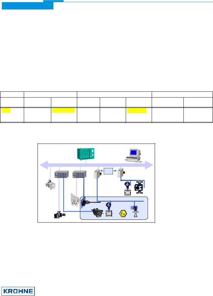
The diagram above shows a typical instrumentation with PROFIBUS-PA devices in hazardous and non-hazardous locations, including connections of conventional devices (e.g. with 4-20mA signals) to the PROFIBUS-PA.
The PROFIBUS-PA is normally connected to a segment coupler which, among other things, carries out the conversion to the PROFIBUS-DP. Here, it needs to be noted in particular that the segment coupler is normally set to a fixed baud rate on the DP side.
Further information on the planning and operation of PROFIBUS-PA networks is to be found in the KROHNE brochure ”PROFIBUS-PA Networks”.
KROHNE Messtechnik GmbH & Co. KG · Ludwig-Krohne-Str. 5 D-47058 Duisburg |
3/17 |
Tel.: 0203-301 309 Fax: 0203-301389 · e-mail: krohne@krohne.de |
|

Supplementary documentation UFC030 with PROFIBUS-PA
4.1Profiles
The UFC030 (UFC 3 Beam) supports the PROFIBUS -PA Profile Version 3.0. Additionally, all relevant parameters of the device are accessible via the PROFIBUS-PA interface (if the manufacturer specific Ident-no is chosen and the manufacturer specific GSD-file version is used).
The UFC030 (UFC 3 Beam) defines the following blocks:
∙One physical block.
This block contains the parameters defined in Profile 3.0.
∙One transducer block for ultrasonic flow meter devices.
This block provides the parameters and functions defined in Profile 3.0. Attached you will find here all the values not defined by the profile.
∙Three “Analog Input (AI)” function blocks: “Volume Flow”, “Speed of Sound” and “CORR. Volume Flow or HEAT Flow (depends on the current device type selection)”.
∙Two “Totalizer (TOT)” function blocks: totalized “Volume” and totalized “CORR. Volume or HEAT (depends on the current device type selection)”.
4.2Services
The UFC030 supports the following PROFIBUS-PA services being defined in the PROFIBUS-PA Profile V3.0:
1.DDLM_Set_Slave_Add
2.DDLM_Get_Cfg
3.DDLM_Set_Prm
4.DDLM_Chk_Cfg
5.DDLM_Slave_Diag
6.DDLM_Data_Exchange
The services mentioned above will enable the customer to set the PROFIBUS-PA station address (1), to configure the data telegram for the cyclic data exchange (3/4), to read back the current PROFIBUS-PA configuration (2) and to read the current Diagnostic data (5).
The service “cyclic data exchange” (6) will be used to transmit the function block output values (measurement data) to a master.
4.3GSD Files
All available GSD files of KROHNE devices – including those of together with each device. The GSD file contains information PROFIBUS -DP/PA communication network. The relevant data system/master system before start-up of the bus system.
UFC030 (UFC 3 Beam), of course - are supplied that will be needed for project planning of the files must be loaded into the project planning
The UFC030 (UFC 3 Beam) is supporting the entire PROFIBUS-PA profile V 3.0. The device has two Ident-no. and two GSD files:
∙Ident-no. “F501” belongs to the GSD file KROHF501.GSD and includesthe complete functionality of the ultrasonic flow meter.
∙The application of the manufacturer independent Ident-no. “9741” (GSD file “PA_9741.GSD”) provides interchangeability of devices, i.e. an exchange of mass flow meters of different vendors.
Please follow the instructions in the manual of the host supplier when installing the GSD File (KROHF501.GSD, UFC3_B_n.bmp, UFC3_B_n.dib) into the PLC.
4.3.1Manufacturer specific GSD file: KROHF501.GSD
KROHNE Messtechnik GmbH & Co. KG · Ludwig-Krohne-Str. 5 D-47058 Duisburg |
4/17 |
Tel.: 0203-301 309 Fax: 0203-301389 · e-mail: krohne@krohne.de |
|

Supplementary documentation UFC030 with PROFIBUS-PA
KROHNE delivers the GSD files with the entire device functionality, which is listed below:
Block Number |
Standard-Configuration |
KROHF701.GSD |
|
|
|
|
(function block output value) |
Ident-No. F701 |
|
|
1 |
Volume Flow |
AI-FB |
|
|
2 |
Speed of Sound |
AI-FB |
|
|
3 |
Volume Totalizer |
Totalizer-FB |
|
|
4 |
CORR. Volume Flow or HEAT Flow * |
AI-FB |
|
|
5 |
CORR. Volumeor HEATTotalizer * |
Totalizer-FB |
|
AI |
= Analog Input Function Block |
|
|
|
FB |
= Function Block |
|
|
|
∙= depends on the current device type selection
Important Notes:
1.To project the PROFIBUS communication network you have to allocate each block to a function. On the PC-S7 from Siemens this will be done with the Tool named “HWConfig”. This tool offers the functions described as follows:
2.It is possible to program an “Empty” block (the code of an “Empty” block is defined as 0x00) on each block number. This means, that for this block no data are transmitted in the cyclic data telegram.
3.There is NO “Totalizer (TOT)” function block allowed on block position 1, 2 and 4! A “Analog Input (AI)” function block or a “Empty” block is allowed here only! That means a “Totalizer (TOT)” function block is not possible at this positions.
Note: All codes of “Analog Input (AI)” - and “Totalizer (TOT)” – function blocks valid for use will be find in the corresponding GSD files.
4.There is NO “Analog Input (AI)” function block allowed on block position 3 and 5! A “Totalizer (TOT)” function block or a “Empty” block is allowed here only! That means a “Analog Input (AI)” function block is not possible at this positions.
5.There is a choice of 4 different totalizer functions, which can be allocated to the blocks 3 and / or 5. The 4 functions are defined as follows:
Function “Totalizer” |
cyclic transfer of the totalizer with status to the master |
Function “SetTot_Total” |
cyclic transfer of the totalizer with status to the master + cyclic control data |
|
from master to the device via the Bytes SetTot |
Function “ModeTot_Total” |
cyclic transfer of the totalizer with status to the master + cyclic control data |
|
from master to the device via the Bytes ModeTot |
Function “SetTot_ModeTot_Total” cyclic transfer of the totalizer with status to the master + cyclic control data from master to the device via the Bytes SetTot and after that ModeTot
Both, the Byte SetTot and ModeTot are being sent cyclical from the Master to the device if these bytes are inserted as output data via the to the PLC configurator. The meaning of these control bytes are as follows:
SetTot: |
|
SetTot =0: |
Totalizer is totalizing. |
SetTot =1: |
Totalizer will be reset to 0 and stays at 0 until SetTot is switched back again to 0. If the value of |
|
SetTot changes from “1” to “0” the totalizer starts counting from 0. |
SetTot =2: |
Totalizer is set to the value defined by PresetTot. PresetTot can be written via a acyclic master |
|
(totalizer in block 3 = Slot 3 Index 32; totalizer in block 5 = Slot 5 Index 32).If the value of SetTot |
|
changes from “1” to “0” the totalizer starts counting from the current value defined by PresetTot. |
SetTot > 2: |
not allowed |
ModeTot:
ModeTot = 0 totalizer totalizes positive and negative values.
KROHNE Messtechnik GmbH & Co. KG · Ludwig-Krohne-Str. 5 D-47058 Duisburg |
5/17 |
Tel.: 0203-301 309 Fax: 0203-301389 · e-mail: krohne@krohne.de |
|

Supplementary documentation UFC030 with PROFIBUS-PA
ModeTot = 1 totalizes only positive values.
ModeTot = 2 totalizes only negative values.
ModeTot = 3 totalizer is stopped, no totalization will be done.
ModeTot > 3 not allowed
6.The standard block confi guration may be changed by the customer but using the default settings is highly recommended. If the standard block configuration should be changed by the customer a acyclic master tool must be used to change the “channel parameter” value of the block which should be connected to another transducer output value.
4.3.2Profile specific GSD file: PA_9741.GSD
The functionality of the profile specific GSD file is limited. This GSD file includes only three blocks: Volume Flow, Speed of Sound (Sound Velocity) and Volume Flow totalizer.
You need the PA_9741 file to use this functionality. Before this, the communication has to be projected and it has to be switched from “full functionality” to “interchangeable basic configuration” by using a master class 2 tool
(IDENT_NUMBER_SELECTOR: Slot 0, Index 40 change byte value from 1 to 0). After this has been done, the device has to be projected by using the PA _9741 file.
4.4Cyclic data exchange
During network configuration the user has to define which function block outputs of the UFC030 (UFC 3 Beam) should be transferred cyclically to the master. The following function block outputs are available in this order:
1.Volume Flow and Status
2.Speed of Sound und Status
3.Volume Totalizer and Status
4.CORR. Volume Flow or HEAT Flow * and Status
5.CORR. Volumeor HEATTotalizer * and Status
∙depends on the current device type selection
Note: If a function block output is chosen for cyclical data transfer the value "Not_a_Number" (0x7FFFFFFF) will be transmitted if the function block itself is not available (due to the current device type selection). If so the status is "Bad-Out of Service".
Network configuration will be done by a master class 2 tool using one of the GSD files described above. The function block outputs which should be transmitted cyclically may be chosen without any restriction. The order of transmission always remains the same even if a function block is defined as an “Empty” block (if so no function block output data will be send to the master and all function block outputs following the “Empty” block will move up one position).
4.5Data Structure of Function Block Output Values
The data structure of function block outputs consists of 5 bytes: a 4 byte float value (Float Format according IEEE Standard 754 Short Real Number) followed by a 1 byte status value. If all 5 function block outputs have been projected (see above), 25 byte will be transmitted.
4.5.1Float Value
First an example of the float format:
|
|
|
Byte n |
|
|
|
Byte n+1 |
|
|
|
|
Byte n+2 |
|
|
|
|
|
Byte n+3 |
|||||||||||||
Bit7 |
Bit6 |
Bit7 |
Bit6 |
|
|
Bit7 |
|
|
Bit7 |
||||||||||||||||||||||
VZ |
27 |
26 |
25 |
24 |
23 |
22 |
21 |
20 |
2-1 |
2-2 |
2-3 |
2-4 |
2-5 |
2-6 |
2-7 |
2-8 |
2-9 |
2-10 |
2-11 |
2-12 |
2-13 |
2-14 |
2-15 |
2-16 |
2-17 |
2-18 |
2-19 |
2-20 |
2-21 |
2-22 |
2-23 |
|
|
|
|
Exponent |
|
|
|
Mantisse |
|
|
|
|
Mantisse |
|
|
|
|
|
Mantisse |
||||||||||||
Example: |
40 F0 00 00 (hex) = 0100 0000 1111 0000 0000 0000 0000 0000 (binary) |
|
|
Formula: |
Value = (-1)VZ * 2 (Exponent - 127) * (1 + Mantisse) |
|
|
|
|
|
|
|
|
KROHNE Messtechnik GmbH & Co. KG · Ludwig-Krohne-Str. 5 D-47058 Duisburg |
6/17 |
|
|
Tel.: 0203-301 309 Fax: 0203-301389 · e-mail: krohne@krohne.de |
|
 Loading...