


SUMMIT 8800 Handbook
Flow Computer
Volume 1: Operation
© KROHNE 08/2013 - MA SUMMIT 8800 Vol 1 R02 en
|
IMPRINT |
|
|
SUMMIT 8800 |
|
|
|
|
All rights reserved. It is prohibited to reproduce this documentation, or any part thereof, without the prior written authorisation of KROHNE Messtechnik GmbH.
Subject to change without notice.
Copyright 2013 by
KROHNE Messtechnik GmbH - Ludwig-Krohne-Str. 5 - 47058 Duisburg (Germany)
2 |
www.krohne.com |
08/2013 - MA SUMMIT 8800 Vol1 R02 en |

|
CONTENTS |
|
SUMMIT 8800 |
|
|
|
|
|
1 About this book |
14 |
1.1 Volumes.............................................................................................................................. |
14 |
1.2 Content Volume 1............................................................................................................... |
14 |
1.3 Content Volume 2............................................................................................................... |
14 |
1.4 Content Volume 3............................................................................................................... |
15 |
1.5 Information in this handbook............................................................................................. |
15 |
2 General Information |
16 |
2.1 Software versions used for this guide............................................................................... |
16 |
2.2 Terminology and Abbreviations......................................................................................... |
16 |
3 Description |
17 |
3.1 SUMMIT 8800 Hardware.................................................................................................... |
17 |
3.1.1 SUMMIT 8800 Flow Computer.................................................................................................. |
17 |
3.1.2 SUMMIT 8800 basic functions................................................................................................... |
17 |
3.1.3 SUMMIT 8800 front panel layout............................................................................................... |
18 |
3.1.4 Rear Panel Layout..................................................................................................................... |
19 |
3.1.5 Alarms & LED’s......................................................................................................................... |
19 |
3.1.6 Description of Hardware memory devices............................................................................... |
20 |
3.2 Features SUMMIT 8800...................................................................................................... |
21 |
3.2.1 Key Features............................................................................................................................. |
21 |
3.2.2 Calculations & Compliance standards..................................................................................... |
22 |
3.3 Integration possibilities..................................................................................................... |
22 |
3.3.1 System Integration.................................................................................................................... |
22 |
3.3.2 Application integration.............................................................................................................. |
23 |
4 Installation and Replacement |
24 |
4.1 Mechanical Specifications................................................................................................. |
24 |
4.1.1 Mechanical Installation............................................................................................................. |
24 |
4.1.2 Panel Mounting......................................................................................................................... |
25 |
4.1.3 Rack mounting options............................................................................................................. |
26 |
4.1.4 Cable Assembly ....................................................................................................................... |
26 |
4.2 Electrical Specifications.................................................................................................... |
27 |
4.2.1 Electrical Installation................................................................................................................ |
27 |
4.2.2 Earthing Requirements............................................................................................................ |
28 |
4.2.3 Fuses and Battery..................................................................................................................... |
28 |
4.2.4 Power Supply Terminals........................................................................................................... |
29 |
4.2.5 Back Up Battery ....................................................................................................................... |
30 |
4.2.6 Real time clock......................................................................................................................... |
33 |
08/2013 - MA SUMMIT 8800 Vol1 R02 en |
www.krohne.com |
3 |

|
CONTENTS |
|
|
SUMMIT 8800 |
|
|
|
|
5 Hardware Details |
34 |
5.1 Front Panel......................................................................................................................... |
34 |
5.1.1 Associated software.................................................................................................................. |
34 |
5.2 Rear Panel.......................................................................................................................... |
34 |
5.2.1 Removal of the Rear Panel....................................................................................................... |
34 |
5.2.2 Rear panel Mode Switches....................................................................................................... |
35 |
5.2.3 SD Card..................................................................................................................................... |
36 |
5.3 Standard hardware components....................................................................................... |
37 |
5.3.1 CPU Board Description............................................................................................................. |
38 |
5.3.2 PSU Board Description............................................................................................................. |
38 |
5.3.3 Auxiliary Board Description...................................................................................................... |
39 |
5.4 Optional Plug-in boards..................................................................................................... |
40 |
5.4.1 Board Selection......................................................................................................................... |
40 |
5.4.2 Terminal Connectors................................................................................................................ |
41 |
5.4.3 Serial Communication Connection........................................................................................... |
42 |
5.5 Digital I/O Board................................................................................................................. |
42 |
5.5.1 Digital I/O Board 1 terminal connections................................................................................. |
43 |
5.5.2 Digital I/O Board 1 Settings...................................................................................................... |
43 |
5.6 Digital I/O Board 2.............................................................................................................. |
45 |
5.6.1 Digital /O Board 2 Terminal Connections................................................................................. |
45 |
5.6.2 Digital I/O Board 2 Settings...................................................................................................... |
46 |
5.7 Analog I/O Board ............................................................................................................... |
47 |
5.7.1 Analog I/O Board Terminal Connections.................................................................................. |
48 |
5.7.2 Analog I/O Board Settings......................................................................................................... |
48 |
5.8 Switch I/O Board ............................................................................................................... |
50 |
5.8.1 Switch I/O Board Terminal Connections................................................................................... |
51 |
5.8.2 Switch I/O Board Settings......................................................................................................... |
51 |
5.9 Ethernet boards................................................................................................................. |
53 |
5.9.1 Ethernet Board Terminal Connections .................................................................................... |
54 |
5.9.2 Dual Ethernet Board Settings................................................................................................... |
55 |
5.9.3 Single Ethernet Board Settings................................................................................................ |
55 |
5.10 DSfG Board....................................................................................................................... |
56 |
5.10.1 DSfG Board installation.......................................................................................................... |
57 |
5.10.2 DSfG Board Terminal Connections......................................................................................... |
58 |
5.10.3 Boards block diagram............................................................................................................. |
59 |
6 Connecting To Field Devices |
60 |
6.1 Transmitters & Transducers.............................................................................................. |
60 |
6.1.1 HART Transmitter Input Connections...................................................................................... |
60 |
6.1.2 Digital Transmitter Input Connections..................................................................................... |
61 |
6.1.3 Digital Transmitter Output Connections................................................................................... |
63 |
6.1.4 Analog Transmitter Input Connections.................................................................................... |
64 |
6.1.5 Analog Transmitter Output Connection.................................................................................... |
66 |
6.1.6 Direct RTD Input Connections.................................................................................................. |
66 |
6.1.7 Pulse Bus.................................................................................................................................. |
67 |
6.2 RS 232/RS485 Communications Connections................................................................... |
68 |
4 |
www.krohne.com |
08/2013 - MA SUMMIT 8800 Vol1 R02 en |

|
CONTENTS |
|
SUMMIT 8800 |
|
|
|
|
|
7 Operation |
70 |
7.1 Initialising .......................................................................................................................... |
70 |
7.2 Front Panel Operation........................................................................................................ |
70 |
7.2.1 Touch Panel............................................................................................................................... |
70 |
7.2.2 Navigator................................................................................................................................... |
71 |
7.2.3 Navigation Controls Main Menu............................................................................................... |
71 |
7.2.4 Main Menu Display.................................................................................................................... |
71 |
8 Calibration |
83 |
8.1 Input Calibration................................................................................................................ |
83 |
8.1.1 HART Input ............................................................................................................................... |
83 |
8.1.2 RTD Input.................................................................................................................................. |
84 |
8.1.3 Analog Input Calibration........................................................................................................... |
84 |
8.1.4 Digital Input............................................................................................................................... |
86 |
8.2 Output Calibration.............................................................................................................. |
86 |
8.2.1 Analog Output........................................................................................................................... |
86 |
8.2.2 Digital Output ........................................................................................................................... |
87 |
9 Web Access |
88 |
9.1 Login................................................................................................................................... |
88 |
9.2 The main page / display page............................................................................................ |
89 |
9.3 The information page......................................................................................................... |
90 |
9.4 The alarm page.................................................................................................................. |
90 |
9.5 The Audit page:.................................................................................................................. |
91 |
9.6 The active data page.......................................................................................................... |
91 |
9.7 Download............................................................................................................................ |
92 |
10 Configuration Software |
94 |
10.1 Introduction...................................................................................................................... |
94 |
10.1.1 Start the configurator............................................................................................................. |
94 |
10.1.2 Select the preferred engineering units.................................................................................. |
95 |
10.1.3 Install an additional user........................................................................................................ |
95 |
10.2 USB Driver installation.................................................................................................... |
97 |
10.3 Main functions of the configurator.................................................................................. |
98 |
10.4 Connect to a Summit....................................................................................................... |
99 |
10.5 Working with configuration set-up’s.............................................................................. |
101 |
10.5.1 Security................................................................................................................................. |
102 |
10.5.2 New configuration................................................................................................................. |
103 |
10.5.3 Load a configuration............................................................................................................. |
104 |
08/2013 - MA SUMMIT 8800 Vol1 R02 en |
www.krohne.com |
5 |

|
CONTENTS |
|
|
SUMMIT 8800 |
|
|
|
|
10.5.4 Save a configuration.............................................................................................................. |
106 |
10.5.5 Upload a configuration.......................................................................................................... |
106 |
10.5.6 Download a configuration..................................................................................................... |
107 |
10.6 Edit menu....................................................................................................................... |
108 |
10.7 On-line (connection) menu............................................................................................ |
110 |
10.7.1 Read Setup............................................................................................................................ |
111 |
10.7.2 Read Alarms......................................................................................................................... |
111 |
10.7.3 Read Log Data....................................................................................................................... |
112 |
10.7.4 Read Data Reports................................................................................................................ |
113 |
10.7.5 Read Audit Log...................................................................................................................... |
114 |
10.7.6 Clear Data............................................................................................................................. |
115 |
10.7.7 Battery Status....................................................................................................................... |
115 |
10.7.8 Script Debug.......................................................................................................................... |
115 |
10.7.9 Process Monitor.................................................................................................................... |
115 |
10.7.10 Check Threads.................................................................................................................... |
115 |
10.7.11 Check Memory Pool............................................................................................................ |
116 |
10.7.12 Read Unit Information......................................................................................................... |
117 |
10.7.13 Log off and close................................................................................................................. |
117 |
11 Firmware |
118 |
11.1 Introduction.................................................................................................................... |
118 |
11.1.1 Firmware description............................................................................................................ |
118 |
11.1.2 Firmware Versions................................................................................................................ |
119 |
11.2 Installation..................................................................................................................... |
119 |
11.3 Use of the wizard............................................................................................................ |
119 |
11.3.1 Upgrading firmware boot/main version............................................................................... |
120 |
12 Display Monitor |
122 |
13 Appendix 1: Software Versions |
123 |
13.1 Versions/ Revisions........................................................................................................ |
123 |
13.2 Current versions............................................................................................................ |
123 |
13.2.1 Latest version 0.35.0.0.......................................................................................................... |
123 |
13.2.2 Approved version MID2.4.0.0................................................................................................ |
123 |
14 Appendix 2: Signal Allocation Forms |
125 |
14.1 Example.......................................................................................................................... |
125 |
14.1.1 Digital /O Board 1 Terminal Connections............................................................................. |
126 |
14.1.2 Digital /O Board 2 Terminal Connections............................................................................. |
127 |
14.1.3 Analog /O Board Terminal Connections............................................................................... |
128 |
14.1.4 Switch Board Terminal Connections.................................................................................... |
129 |
14.1.5 Dual Ethernet Board Terminal Connections........................................................................ |
130 |
6 |
www.krohne.com |
08/2013 - MA SUMMIT 8800 Vol1 R02 en |

|
CONTENTS |
|
SUMMIT 8800 |
|
|
|
|
|
14.1.6 Single Ethernet Board Terminal Connections...................................................................... |
131 |
14.1.7 DSfG Board Terminal Connections....................................................................................... |
132 |
15 Appendix 3: Technical Data |
133 |
15.1 General........................................................................................................................... |
133 |
15.2 Inputs............................................................................................................................. |
133 |
15.3 Outputs........................................................................................................................... |
134 |
15.3.1 Communication..................................................................................................................... |
134 |
15.3.2 Power Supply........................................................................................................................ |
135 |
15.4 Data sheet...................................................................................................................... |
135 |
15.4.1 Ordering Options................................................................................................................... |
138 |
15.4.2 Replacement Parts............................................................................................................... |
139 |
16 Appendix 4: Install The Configurator |
140 |
08/2013 - MA SUMMIT 8800 Vol1 R02 en |
www.krohne.com |
7 |
|
TABLE OF FIGURES |
|
|
SUMMIT 8800 |
|
|
|
|
Figure 1 Front view of Summit 8800.. . . . . . . . . . . . . . . . . . . . . . . . . . . . . . . . . . . . . . . . . . . . . . . . . . . . . . . . . . . . . . . . . |
18 |
Figure 2 Rear view of SUMMIT 8800.. . . . . . . . . . . . . . . . . . . . . . . . . . . . . . . . . . . . . . . . . . . . . . . . . . . . . . . . . . . . . . . . . |
19 |
Figure 3 LED indicators. . . . . . . . . . . . . . . . . . . . . . . . . . . . . . . . . . . . . . . . . . . . . . . . . . . . . . . . . . . . . . . . . . . . . . . . . . . . |
19 |
Figure 4 SUMMIT 8800 system integration overview. . . . . . . . . . . . . . . . . . . . . . . . . . . . . . . . . . . . . . . . . . . . . . . . . . . . |
23 |
Figure 5 Stream application integration . . . . . . . . . . . . . . . . . . . . . . . . . . . . . . . . . . . . . . . . . . . . . . . . . . . . . . . . . . . . . . |
23 |
Figure 6 Dimensions & Outlines. . . . . . . . . . . . . . . . . . . . . . . . . . . . . . . . . . . . . . . . . . . . . . . . . . . . . . . . . . . . . . . . . . . . . |
25 |
Figure 7 Panel mounted installations.. .. .. .. .. .. .. .. .. .. .. .. .. .. .. .. .. .. .. .. .. .. .. .. .. .. .. .. .. .. .. .. .. .. .. .. .. .. .. .. .. .. .. .. .. .. .. .. .. .. .. .. .. .. .. .. .. .. .. .. .. .. .. .. |
25 |
Figure 8 Rack mounting kit. . . . . . . . . . . . . . . . . . . . . . . . . . . . . . . . . . . . . . . . . . . . . . . . . . . . . . . . . . . . . . . . . . . . . . . . . |
26 |
Figure 9 Rack mounted installation. . . . . . . . . . . . . . . . . . . . . . . . . . . . . . . . . . . . . . . . . . . . . . . . . . . . . . . . . . . . . . . . . . |
26 |
Figure 10 Cable assembly . . . . . . . . . . . . . . . . . . . . . . . . . . . . . . . . . . . . . . . . . . . . . . . . . . . . . . . . . . . . . . . . . . . . . . . . . . |
27 |
Figure 11 Fuse F1 (left) en F2 (right) . . . . . . . . . . . . . . . . . . . . . . . . . . . . . . . . . . . . . . . . . . . . . . . . . . . . . . . . . . . . . . . . . |
29 |
Figure 12 Power & M4 earth connections . . . . . . . . . . . . . . . . . . . . . . . . . . . . . . . . . . . . . . . . . . . . . . . . . . . . . . . . . . . . . |
30 |
Figure 13 Configurator good and bad battery indicator. . . . . . . . . . . . . . . . . . . . . . . . . . . . . . . . . . . . . . . . . . . . . . . . . . |
31 |
Figure 14 Bad battery indicator on front panel. . . . . . . . . . . . . . . . . . . . . . . . . . . . . . . . . . . . . . . . . . . . . . . . . . . . . . . . . |
31 |
Figure 15 Totalizers enter field.. . . . . . . . . . . . . . . . . . . . . . . . . . . . . . . . . . . . . . . . . . . . . . . . . . . . . . . . . . . . . . . . . . . . . |
32 |
Figure 16 Auxiliary board . . . . . . . . . . . . . . . . . . . . . . . . . . . . . . . . . . . . . . . . . . . . . . . . . . . . . . . . . . . . . . . . . . . . . . . . . . |
32 |
Figure 17 Front panel of SUMMIT 8800 & USB port . . . . . . . . . . . . . . . . . . . . . . . . . . . . . . . . . . . . . . . . . . . . . . . . . . . . . |
34 |
Figure 18 Rear panel of SUMMIT 8800 and removal screws. . . . . . . . . . . . . . . . . . . . . . . . . . . . . . . . . . . . . . . . . . . . . . |
35 |
Figure 19 Mode Switch settings . . . . . . . . . . . . . . . . . . . . . . . . . . . . . . . . . . . . . . . . . . . . . . . . . . . . . . . . . . . . . . . . . . . . . |
35 |
Figure 20 System information screen . . . . . . . . . . . . . . . . . . . . . . . . . . . . . . . . . . . . . . . . . . . . . . . . . . . . . . . . . . . . . . . . |
36 |
Figure 21 Illustration of inserted SD card. . . . . . . . . . . . . . . . . . . . . . . . . . . . . . . . . . . . . . . . . . . . . . . . . . . . . . . . . . . . . |
37 |
Figure 22 Modular design chassis . . . . . . . . . . . . . . . . . . . . . . . . . . . . . . . . . . . . . . . . . . . . . . . . . . . . . . . . . . . . . . . . . . . |
37 |
Figure 23 Board slots with mother board & rear view panel.. . . . . . . . . . . . . . . . . . . . . . . . . . . . . . . . . . . . . . . . . . . . . |
38 |
Figure 24 Power supply unit . . . . . . . . . . . . . . . . . . . . . . . . . . . . . . . . . . . . . . . . . . . . . . . . . . . . . . . . . . . . . . . . . . . . . . . . |
38 |
Figure 25 PSU board components. . . . . . . . . . . . . . . . . . . . . . . . . . . . . . . . . . . . . . . . . . . . . . . . . . . . . . . . . . . . . . . . . . . |
39 |
Figure 26 Auxiliary board. . . . . . . . . . . . . . . . . . . . . . . . . . . . . . . . . . . . . . . . . . . . . . . . . . . . . . . . . . . . . . . . . . . . . . . . . . |
39 |
Figure 27 Auxiliary board components. . . . . . . . . . . . . . . . . . . . . . . . . . . . . . . . . . . . . . . . . . . . . . . . . . . . . . . . . . . . . . . |
40 |
Figure 28 Typical I/O board . . . . . . . . . . . . . . . . . . . . . . . . . . . . . . . . . . . . . . . . . . . . . . . . . . . . . . . . . . . . . . . . . . . . . . . . . |
40 |
Figure 29 Illustration method of cable insertion into clamp. . . . . . . . . . . . . . . . . . . . . . . . . . . . . . . . . . . . . . . . . . . . . . |
41 |
Figure 30 Serial port I/O boards rear terminal pin allocation.. . . . . . . . . . . . . . . . . . . . . . . . . . . . . . . . . . . . . . . . . . . . |
42 |
Figure 31 Digital I/O board 1 rear terminal pin allocation. . . . . . . . . . . . . . . . . . . . . . . . . . . . . . . . . . . . . . . . . . . . . . . . |
43 |
Figure 32 Digital I/O board digital input link setting .. . . . . . . . . . . . . . . . . . . . . . . . . . . . . . . . . . . . . . . . . . . . . . . . . . |
44 |
Figure 33 Digital I/O board HART loop link settings . . . . . . . . . . . . . . . . . . . . . . . . . . . . . . . . . . . . . . . . . . |
44 |
Figure 34 Digital I/O board RS485 termination link setting .. . . . . . . . . . . . . . . . . . . . . . . . . . . . . . . . . . . . . . . |
44 |
Figure 35 Digital I/O board 2 rear terminal pin allocation. . . . . . . . . . . . . . . . . . . . . . . . . . . . . . . . . . . . . . . . . . . . . . . . |
45 |
Figure 36 Digital I/O board digital input link setting .. . . . . . . . . . . . . . . . . . . . . . . . . . . . . . . . . . . . . . . . . . . . . . . . . . . |
46 |
Figure 37 Digital I/O board 2 HART loop link settings . . . . . . . . . . . . . . . . . . . . . . . . . . . . . . . . . . . . . . . . . . . . . . |
46 |
Figure 38 Digital I/O board 2 RS485 termination link setting .. . . . . . . . . . . . . . . . . . . . . . . . . . . . . . . . . . . . . . . . . . . . |
47 |
Figure 39 Analog I/O board rear terminal pin allocation. . . . . . . . . . . . . . . . . . . . . . . . . . . . . . . . . . . . . . . . . . . . . . . . . |
48 |
Figure 40 Analog I/O board digital input link settings . . . . . . . . . . . . . . . . . . . . . . . . . . . . . . . . . . . . . . . . . . . . . . . . |
49 |
Figure 41 Analog I/O board HART loop and I/O function link settings . . . . . . . . . . . . . . . . . . . . . . . . . . . . . . . . . . . . . . |
49 |
Figure 42 Analog I/O board RS485 termination link setting . . . . . . . . . . . . . . . . . . . . . . . . . . . . . . . . . . . . . . . . . . . . . . |
50 |
Figure 43 Switch I/O board rear terminal pin allocation . . . . . . . . . . . . . . . . . . . . . . . . . . . . . . . . . . . . . . . . . . . . . . . . . |
51 |
Figure 44 Switch I/O board digital input link setting . . . . . . . . . . . . . . . . . . . . . . . . . . . . . . . . . . . . . . . . . . . . . . . |
52 |
Figure 45 Switch I/O board digital input link settings. . . . . . . . . . . . . . . . . . . . . . . . . . . . . . . . . . . . . . . . . . . . . . . . . . . |
52 |
Figure 46 Switch I/O board RS485 termination link settings.. . . . . . . . . . . . . . . . . . . . . . . . . . . . . . . . . . . . . . . . . . . . . |
53 |
Figure 47 Switch I/O board digital input / output link settings . . . . . . . . . . . . . . . . . . . . . . . . . . . . . . . . . . . . . . . . . . . . |
53 |
Figure 48 Ethernet boards rear terminal pin allocation. . . . . . . . . . . . . . . . . . . . . . . . . . . . . . . . . . . . . . . . . . . . . . . . . |
54 |
Figure 49 Dual Ethernet communication board link setting .. . . . . . . . . . . . . . . . . . . . . . . . . . . . . . . . . . . . . . . . . . . . . |
55 |
Figure 50 Communication board link setting. . . . . . . . . . . . . . . . . . . . . . . . . . . . . . . . . . . . . . . . . . . . . . . . . . . . . . . . . . |
56 |
Figure 51 DSfG communication board .. . . . . . . . . . . . . . . . . . . . . . . . . . . . . . . . . . . . . . . . . . . . . . . . . . . . . . . . . . . . . . . |
57 |
Figure 52 DSfG communication installation . . . . . . . . . . . . . . . . . . . . . . . . . . . . . . . . . . . . . . . . . . . . . . . . . . . . . . . . . . . |
57 |
Figure 53 DSfG boards block diagram . . . . . . . . . . . . . . . . . . . . . . . . . . . . . . . . . . . . . . . . . . . . . . . . . . . . . . . . . . . . . . . . |
59 |
Figure 54 Typical HART transmitter connections. . . . . . . . . . . . . . . . . . . . . . . . . . . . . . . . . . . . . . . . . . . . . . . . . . . . . . . |
60 |
Figure 55 HART multidrop.. . . . . . . . . . . . . . . . . . . . . . . . . . . . . . . . . . . . . . . . . . . . . . . . . . . . . . . . . . . . . . . . . . . . . . . . . |
61 |
Figure 56 Digital Input internal circuit.. . . . . . . . . . . . . . . . . . . . . . . . . . . . . . . . . . . . . . . . . . . . . . . . . . . . . . . . . . . . . . . |
62 |
Figure 57 Digital input density transducer. . . . . . . . . . . . . . . . . . . . . . . . . . . . . . . . . . . . . . . . . . . . . . . . . . . . . . . . . . . . |
62 |
Figure 58 Digital input status optocoupler. . . . . . . . . . . . . . . . . . . . . . . . . . . . . . . . . . . . . . . . . . . . . . . . . . . . . . . . . . . . |
63 |
Figure 59 Digital input pulse status. . . . . . . . . . . . . . . . . . . . . . . . . . . . . . . . . . . . . . . . . . . . . . . . . . . . . . . . . . . . . . . . . . |
63 |
Figure 60 Digital output valve solenoid . . . . . . . . . . . . . . . . . . . . . . . . . . . . . . . . . . . . . . . . . . . . . . . . . . . . . . . . . . . . . . . |
63 |
Figure 61 Typical analog input connections. . . . . . . . . . . . . . . . . . . . . . . . . . . . . . . . . . . . . . . . . . . . . . . . . . . . . . . . . . . |
64 |
Figure 62 Analog input active transmitter loop. . . . . . . . . . . . . . . . . . . . . . . . . . . . . . . . . . . . . . . . . . . . . . . . . . . . . . . . |
64 |
Figure 63 Analog input internal circuit. . . . . . . . . . . . . . . . . . . . . . . . . . . . . . . . . . . . . . . . . . . . . . . . . . . . . . . . . . . . . . . |
65 |
Figure 64 Analog input transmitter isolator loop. . . . . . . . . . . . . . . . . . . . . . . . . . . . . . . . . . . . . . . . . . . . . . . . . . . . . . . |
65 |
Figure 65 Analog input passive transmitter loop . . . . . . . . . . . . . . . . . . . . . . . . . . . . . . . . . . . . . . . . . . . . . . . . . . . . . . . |
65 |
Figure 66 Analog output passive actuator. . . . . . . . . . . . . . . . . . . . . . . . . . . . . . . . . . . . . . . . . . . . . . . . . . . . . . . . . . . . . |
66 |
Figure 67 Direct RTD connection. . . . . . . . . . . . . . . . . . . . . . . . . . . . . . . . . . . . . . . . . . . . . . . . . . . . . . . . . . . . . . . . . . . . |
66 |
Figure 68 Pulse bus loop. . . . . . . . . . . . . . . . . . . . . . . . . . . . . . . . . . . . . . . . . . . . . . . . . . . . . . . . . . . . . . . . . . . . . . . . . . . |
67 |
Figure 69 Start/stop signals loop. . . . . . . . . . . . . . . . . . . . . . . . . . . . . . . . . . . . . . . . . . . . . . . . . . . . . . . . . . . . . . . . . . . . |
68 |
Figure 70 Internal RS485 Termination network . . . . . . . . . . . . . . . . . . . . . . . . . . . . . . . . . . . . . . . . . . . . . . . . . . . . . . . . |
69 |
Figure 71 RS485 multidrop .. . . . . . . . . . . . . . . . . . . . . . . . . . . . . . . . . . . . . . . . . . . . . . . . . . . . . . . . . . . . . . . . . . . . . . |
69 |
8 |
www.krohne.com |
08/2013 - MA SUMMIT 8800 Vol1 R02 en |

|
TABLE OF FIGURES |
|
SUMMIT 8800 |
|
|
|
|
|
Figure 72 SUMMIT 8800 initialization . . |
. . . . . . . . . . . . . . . . . . . . . . . . . . . . . . . . . . . . . . . . . . . . . . . . . . . . . . . . . . . . . . |
70 |
|
Figure 73 Parameter highlighted by Navigator.. . . . . . . . . . . . . . . . . . . . . . . . . . . . . . . . . . . . . . . . . . . . . . . . . . . . . . . . |
71 |
||
Figure 74 Parameter selected by Navigator . . . . . . . . . . . . . . . . . . . . . . . . . . . . . . . . . . . . . . . . . . . . . . . . . . . . . . . . . . . |
71 |
||
Figure 75 Screen navigation and control indicators. . . . . . . . . . . . . . . . . . . . . . . . . . . . . . . . . . . . . . . . . . . . . . . . . . . . . |
71 |
||
Figure 76 Main menu parameters. . . . . . . . . . |
. . . . . . . . . . . . . . . . . . . . . . . . . . . . . . . . . . . . . . . . . . . . . . . . . . . . . . . . . |
72 |
|
Figure 77 Edit mode login screen. . . . . . . |
. . . . . . . . . . . . . . . . . . . . . . . . . . . . . . . . . . . . . . . . . . . . . . . . . . . . . . . . . . . . . |
73 |
|
Figure 78 Enter values screen. . . . . . . . . . . . . . . . |
. . . . . . . . . . . . . . . . . . . . . . . . . . . . . . . . . . . . . . . . . . . . . . . . . . . . . . |
74 |
|
Figure 79 Exit edit screen . . . . . . . . . . . . . |
. . . . . . . . . . . . . . . . . . . . . . . . . . . . . . . . . . . . . . . . . . . . . . . . . . . . . . . . . . . . . |
74 |
|
Figure 80 |
Calibration menu.. . . . . . . . . . . . . . . . . . . . . . . . . . . . . . . . . . . . . . . . . . . . . . . . . . . . . . . . . . . . . . . . . . . . . . . . |
75 |
|
Figure 81 |
Alarm page. . . . . . . . . . . . . . . . . . . . . |
. . . . . . . . . . . . . . . . . . . . . . . . . . . . . . . . . . . . . . . . . . . . . . . . . . . . . . . . |
76 |
Figure 82 Audit Log Example . . . . . . . . . . |
. . . . . . . . . . . . . . . . . . . . . . . . . . . . . . . . . . . . . . . . . . . . . . . . . . . . . . . . . . . . . |
77 |
|
Figure 83 Audit log trail. . . . . . . . . . . . . . . |
. . . . . . . . . . . . . . . . . . . . . . . . . . . . . . . . . . . . . . . . . . . . . . . . . . . . . . . . . . . . . |
77 |
|
Figure 84 Supervisory screen display . . . |
. . . . . . . . . . . . . . . . . . . . . . . . . . . . . . . . . . . . . . . . . . . . . . . . . . . . . . . . . . . . . |
78 |
|
Figure 85 Supervisory Mode Enabled. . . . |
. . . . . . . . . . . . . . . . . . . . . . . . . . . . . . . . . . . . . . . . . . . . . . . . . . . . . . . . . . . . |
78 |
|
Figure 86 System information screen . . . |
. . . . . . . . . . . . . . . . . . . . . . . . . . . . . . . . . . . . . . . . . . . . . . . . . . . . . . . . . . . . . |
79 |
|
Figure 87 Display settings screen. . . . . . . . . |
. . . . . . . . . . . . . . . . . . . . . . . . . . . . . . . . . . . . . . . . . . . . . . . . . . . . . . . . . . |
80 |
|
Figure 88 Display test screen . . . . . . . . . . |
. . . . . . . . . . . . . . . . . . . . . . . . . . . . . . . . . . . . . . . . . . . . . . . . . . . . . . . . . . . . . |
81 |
|
Figure 89 Touch screen calibration. . . . . . . . . |
. . . . . . . . . . . . . . . . . . . . . . . . . . . . . . . . . . . . . . . . . . . . . . . . . . . . . . . . . |
82 |
|
Figure 90 Touch Screen Calibration pages . . . . . . . . . . . . . . . . . . . . . . . . . . . . . . . . . . . . . . . . . . . . . . . . . . . . . . . . . . . . |
82 |
||
Figure 91 Calibrate HART screen. . . . . . . |
. . . . . . . . . . . . . . . . . . . . . . . . . . . . . . . . . . . . . . . . . . . . . . . . . . . . . . . . . . . . . |
83 |
|
Figure 92 RTD Input calibration screen. . |
. . . . . . . . . . . . . . . . . . . . . . . . . . . . . . . . . . . . . . . . . . . . . . . . . . . . . . . . . . . . . |
84 |
|
Figure 93 Calibrate analog input. . . . . . . . . . . |
. . . . . . . . . . . . . . . . . . . . . . . . . . . . . . . . . . . . . . . . . . . . . . . . . . . . . . . . . |
85 |
|
Figure 94 Calibration selection screen. . . . |
. . . . . . . . . . . . . . . . . . . . . . . . . . . . . . . . . . . . . . . . . . . . . . . . . . . . . . . . . . . |
85 |
|
Figure 95 Analog output calibration screen. . . . . . . . . . . . . . . . . . . . . . . . . . . . . . . . . . . . . . . . . . . . . . . . . . . . . . . . . . . |
87 |
||
Figure 96 |
Website login. . . . . . . . . . . . . . . |
. . . . . . . . . . . . . . . . . . . . . . . . . . . . . . . . . . . . . . . . . . . . . . . . . . . . . . . . . . . . . |
88 |
Figure 97 Main Page.. . . . . . . . . . . . . . . . . . . . . . . . . . . . . . . . . . . . . . . . . . . . . . . . . . . . . . . . . . . . . . . . . . . . . . . . . . . . . . |
89 |
||
Figure 98 Main page bar chart . . . . . . . . . |
. . . . . . . . . . . . . . . . . . . . . . . . . . . . . . . . . . . . . . . . . . . . . . . . . . . . . . . . . . . . . |
89 |
|
Figure 99 |
Information page.. . . . . . . . . . . . |
. . . . . . . . . . . . . . . . . . . . . . . . . . . . . . . . . . . . . . . . . . . . . . . . . . . . . . . . . . . . |
90 |
Figure 100 |
Alarm page. . . . . . . . . . . . . . . . . . . . . |
. . . . . . . . . . . . . . . . . . . . . . . . . . . . . . . . . . . . . . . . . . . . . . . . . . . . . . . |
90 |
Figure 101 |
Audit log. . . . . . . . . . . . . . . . . . |
. . . . . . . . . . . . . . . . . . . . . . . . . . . . . . . . . . . . . . . . . . . . . . . . . . . . . . . . . . . . . |
91 |
Figure 102 Active data page. . . . . . . . . . . . . . . . . . |
. . . . . . . . . . . . . . . . . . . . . . . . . . . . . . . . . . . . . . . . . . . . . . . . . . . . . . |
91 |
|
Figure 103 Downloading CSV file . . . . . . . |
. . . . . . . . . . . . . . . . . . . . . . . . . . . . . . . . . . . . . . . . . . . . . . . . . . . . . . . . . . . . . |
92 |
|
Figure 104 |
Import wizard. . . . . . . . . . . . . . . . . . . |
. . . . . . . . . . . . . . . . . . . . . . . . . . . . . . . . . . . . . . . . . . . . . . . . . . . . . . . |
93 |
Figure 105 Finishing the wizard in Excel. . . . . . . . . . . . . . . . . . . . . . . . . . . . . . . . . . . . . . . . . . . . . . . . . . . . . . . . . . . . . . |
93 |
||
Figure 106 Configurator desktop icon . . . |
. . . . . . . . . . . . . . . . . . . . . . . . . . . . . . . . . . . . . . . . . . . . . . . . . . . . . . . . . . . . . |
94 |
|
Figure 107 User login screen. . . . . . . . . . . . . . . . . . . |
. . . . . . . . . . . . . . . . . . . . . . . . . . . . . . . . . . . . . . . . . . . . . . . . . . . . |
94 |
|
Figure 108 Menu Configurator software . |
. . . . . . . . . . . . . . . . . . . . . . . . . . . . . . . . . . . . . . . . . . . . . . . . . . . . . . . . . . . . . |
95 |
|
Figure 109 |
Appearance . . . . . . . . . . . . . . . |
. . . . . . . . . . . . . . . . . . . . . . . . . . . . . . . . . . . . . . . . . . . . . . . . . . . . . . . . . . . . . |
95 |
Figure 110 User creation screen. . . . . . . . . . |
. . . . . . . . . . . . . . . . . . . . . . . . . . . . . . . . . . . . . . . . . . . . . . . . . . . . . . . . . . |
96 |
|
Figure 111 User access level.. . . . . . . . . . . . . . . . . . . . . . . . . . . . . . . . . . . . . . . . . . . . . . . . . . . . . . . . . . . . . . . . . . . . . . . |
96 |
||
Figure 112 24V input power.. . . . . . . . . . . . . |
. . . . . . . . . . . . . . . . . . . . . . . . . . . . . . . . . . . . . . . . . . . . . . . . . . . . . . . . . . . |
97 |
|
Figure 113 |
USB port.. . . . . . . . . . . . . . . . . . |
. . . . . . . . . . . . . . . . . . . . . . . . . . . . . . . . . . . . . . . . . . . . . . . . . . . . . . . . . . . . |
97 |
Figure 114 Driver recognition message.. |
. . . . . . . . . . . . . . . . . . . . . . . . . . . . . . . . . . . . . . . . . . . . . . . . . . . . . . . . . . . . . |
97 |
|
Figure 115 Menu Configurator software . |
. . . . . . . . . . . . . . . . . . . . . . . . . . . . . . . . . . . . . . . . . . . . . . . . . . . . . . . . . . . . . |
98 |
|
Figure 116 |
Connection list.. . . . . . . . . . . . . . |
. . . . . . . . . . . . . . . . . . . . . . . . . . . . . . . . . . . . . . . . . . . . . . . . . . . . . . . . . . . |
99 |
Figure 117 Manual connection list . . . . . . |
. . . . . . . . . . . . . . . . . . . . . . . . . . . . . . . . . . . . . . . . . . . . . . . . . . . . . . . . . . . . . |
100 |
|
Figure 118 |
Reading setup . . . . . . . . . . . . . |
. . . . . . . . . . . . . . . . . . . . . . . . . . . . . . . . . . . . . . . . . . . . . . . . . . . . . . . . . . . . . |
100 |
Figure 119 |
Connection menu. . . . . . . . . . . . . . . . |
. . . . . . . . . . . . . . . . . . . . . . . . . . . . . . . . . . . . . . . . . . . . . . . . . . . . . . . |
101 |
Figure 120 Fully secure error message.. |
. . . . . . . . . . . . . . . . . . . . . . . . . . . . . . . . . . . . . . . . . . . . . . . . . . . . . . . . . . . . . |
102 |
|
Figure 121 Operating dipswitch settings. . . . . . . . . . . . . . . . . . . . . . . . . . . . . . . . . . . . . . . . . . . . . . . . . . . . . . . . . . . . . . |
103 |
||
Figure 122 |
Select version. . . . . . . . . . . . . . . . . . . . . . . . |
. . . . . . . . . . . . . . . . . . . . . . . . . . . . . . . . . . . . . . . . . . . . . . . . . . |
103 |
Figure 123 Select Run type . . . . . . . . . . . . |
. . . . . . . . . . . . . . . . . . . . . . . . . . . . . . . . . . . . . . . . . . . . . . . . . . . . . . . . . . . . . |
104 |
|
Figure 124 Load configuration file . . . . . . |
. . . . . . . . . . . . . . . . . . . . . . . . . . . . . . . . . . . . . . . . . . . . . . . . . . . . . . . . . . . . . |
105 |
|
Figure 125 Load set-up configuration . . . |
. . . . . . . . . . . . . . . . . . . . . . . . . . . . . . . . . . . . . . . . . . . . . . . . . . . . . . . . . . . . . |
105 |
|
Figure 126 |
Save configuration. . . . . . . . . . . . . |
. . . . . . . . . . . . . . . . . . . . . . . . . . . . . . . . . . . . . . . . . . . . . . . . . . . . . . . . . |
106 |
Figure 127 Edit online window . . . . . . . . . |
. . . . . . . . . . . . . . . . . . . . . . . . . . . . . . . . . . . . . . . . . . . . . . . . . . . . . . . . . . . . . |
107 |
|
Figure 128 Edit off-line menu. . . . . . . . . . |
. . . . . . . . . . . . . . . . . . . . . . . . . . . . . . . . . . . . . . . . . . . . . . . . . . . . . . . . . . . . . |
107 |
|
Figure 129 |
Connection list.. . . . . . . . . . . . . . |
. . . . . . . . . . . . . . . . . . . . . . . . . . . . . . . . . . . . . . . . . . . . . . . . . . . . . . . . . . . |
108 |
Figure 130 Download configuration process. . . . . . . . . . . . . . . . . . . . . . . . . . . . . . . . . . . . . . . . . . . . . . . . . . . . . . . . . . . |
108 |
||
Figure 131 |
Edit offline . . . . . . . . . . . . . . . . |
. . . . . . . . . . . . . . . . . . . . . . . . . . . . . . . . . . . . . . . . . . . . . . . . . . . . . . . . . . . . . |
109 |
Figure 132 |
Connection menu. . . . . . . . . . . . . . . . |
. . . . . . . . . . . . . . . . . . . . . . . . . . . . . . . . . . . . . . . . . . . . . . . . . . . . . . . |
111 |
Figure 133 |
Alarm window . . . . . . . . . . . . . |
. . . . . . . . . . . . . . . . . . . . . . . . . . . . . . . . . . . . . . . . . . . . . . . . . . . . . . . . . . . . . |
112 |
Figure 134 Data log selection . . . . . . . . . . |
. . . . . . . . . . . . . . . . . . . . . . . . . . . . . . . . . . . . . . . . . . . . . . . . . . . . . . . . . . . . . |
112 |
|
Figure 135 Data log window. . . . . . . . . . . . . . . . . . |
. . . . . . . . . . . . . . . . . . . . . . . . . . . . . . . . . . . . . . . . . . . . . . . . . . . . . . |
113 |
|
Figure 136 Data report window.. . . . . . . . . . |
. . . . . . . . . . . . . . . . . . . . . . . . . . . . . . . . . . . . . . . . . . . . . . . . . . . . . . . . . . . |
114 |
|
Figure 137 Audit log window. . . . . . . . . . . |
. . . . . . . . . . . . . . . . . . . . . . . . . . . . . . . . . . . . . . . . . . . . . . . . . . . . . . . . . . . . . |
114 |
|
Figure 138 Configurator good battery status. . . . . . . . . . . . . . . . . . . . . . . . . . . . . . . . . . . . . . . . . . . . . . . . . . . . . . . . . . |
115 |
||
Figure 139 Check threads display. . . . . . . . . |
. . . . . . . . . . . . . . . . . . . . . . . . . . . . . . . . . . . . . . . . . . . . . . . . . . . . . . . . . . |
116 |
|
Figure 140 Check memory pool display.. |
. . . . . . . . . . . . . . . . . . . . . . . . . . . . . . . . . . . . . . . . . . . . . . . . . . . . . . . . . . . . . |
116 |
|
Figure 141 |
Firmware illustration . . . . . . . |
. . . . . . . . . . . . . . . . . . . . . . . . . . . . . . . . . . . . . . . . . . . . . . . . . . . . . . . . . . . . . |
119 |
Figure 142 Upgrade mode switch. . . . . . . |
. . . . . . . . . . . . . . . . . . . . . . . . . . . . . . . . . . . . . . . . . . . . . . . . . . . . . . . . . . . . . |
120 |
|
08/2013 - MA SUMMIT 8800 Vol1 R02 en |
www.krohne.com |
9 |
|
|
TABLE OF FIGURES |
|
|
SUMMIT 8800 |
|
|
|
|
Figure 143 USB cable port.. . . . . . . . . . . . . . . . . . . . . . . . . . . . . . . . . . . . . . . . . . . . . . . . . . . . . . . . . . . . . . . . . . . . . . . . . |
120 |
Figure 144 Input power . . . . . . . . . . . . . . . . . . . . . . . . . . . . . . . . . . . . . . . . . . . . . . . . . . . . . . . . . . . . . . . . . . . . . . . . . . . . |
120 |
Figure 145 Update wizard windows . . . . . . . . . . . . . . . . . . . . . . . . . . . . . . . . . . . . . . . . . . . . . . . . . . . . . . . . . . . . . . . . . . |
121 |
Figure 146 Configurator Wizard screen.. . . . . . . . . . . . . . . . . . . . . . . . . . . . . . . . . . . . . . . . . . . . . . . . . . . . . . . . . . . . . . |
140 |
Figure 147 Configurator file location . . . . . . . . . . . . . . . . . . . . . . . . . . . . . . . . . . . . . . . . . . . . . . . . . . . . . . . . . . . . . . . . . |
140 |
Figure 148 Configurator program location . . . . . . . . . . . . . . . . . . . . . . . . . . . . . . . . . . . . . . . . . . . . . . . . . . . . . . . . . . . . |
141 |
Figure 149 Configurator install features. . . . . . . . . . . . . . . . . . . . . . . . . . . . . . . . . . . . . . . . . . . . . . . . . . . . . . . . . . . . . . |
141 |
Figure 150 Software installation process. . . . . . . . . . . . . . . . . . . . . . . . . . . . . . . . . . . . . . . . . . . . . . . . . . . . . . . . . . . . . |
142 |
Figure 151 Completion window.. . . . . . . . . . . . . . . . . . . . . . . . . . . . . . . . . . . . . . . . . . . . . . . . . . . . . . . . . . . . . . . . . . . . . |
142 |
Figure 152 Add user window.. . . . . . . . . . . . . . . . . . . . . . . . . . . . . . . . . . . . . . . . . . . . . . . . . . . . . . . . . . . . . . . . . . . . . . . |
142 |
Figure 153 Edit user window.. . . . . . . . . . . . . . . . . . . . . . . . . . . . . . . . . . . . . . . . . . . . . . . . . . . . . . . . . . . . . . . . . . . . . . . |
143 |
10 |
www.krohne.com |
08/2013 - MA SUMMIT 8800 Vol1 R02 en |
|
TABLES |
|
SUMMIT 8800 |
|
|
|
|
|
Table 1 Location of fuses on PSU.............................................................................................................................................. |
39 |
Table 2 Boards with available Inputs & Outputs....................................................................................................................... |
41 |
Table 3 Digital I/O board 1 link settings.................................................................................................................................... |
44 |
Table 4 HART loop settings on digital I/O board 1.................................................................................................................... |
44 |
Table 5 Serial settings on digital I/O board 1............................................................................................................................ |
44 |
Table 6 Digital I/O board 2 settings........................................................................................................................................... |
46 |
Table 7 HART loop settings on digital I/O board 2.................................................................................................................... |
46 |
Table 8 Serial settings on digital I/O board 2............................................................................................................................ |
47 |
Table 9 Digital input link settings on analog board.................................................................................................................. |
49 |
Table 10 HART and I/O functions settings on analog board..................................................................................................... |
49 |
Table 11 Serial settings on analog I/O board............................................................................................................................ |
50 |
Table 12 Switch I/O digital input settings................................................................................................................................. |
52 |
Table 13 Switch I/O board digital settings................................................................................................................................ |
52 |
Table 14 Serial settings on switch I/O board............................................................................................................................ |
53 |
Table 15 Switch I/O board digital settings................................................................................................................................ |
53 |
Table 16 Communication board configuration.......................................................................................................................... |
53 |
Table 17 Dual Ethernet serial settings..................................................................................................................................... |
55 |
Table 18 Dual Ethernet port LED indicators............................................................................................................................. |
55 |
Table 19 Single Ethernet serial settings................................................................................................................................... |
56 |
Table 20 Single Ethernet port LED indicators.......................................................................................................................... |
56 |
Table 21 Digital transmitter reference voltage and resistance................................................................................................ |
61 |
08/2013 - MA SUMMIT 8800 Vol1 R02 en |
www.krohne.com |
11 |

|
ABOUT THIS HANDBOOK |
|
01 |
SUMMIT 8800 |
|
|
|
|
12 |
www.krohne.com |
08/2013 - MA SUMMIT 8800 Vol1 R02 en |

|
ABOUT THIS HANDBOOK |
|
SUMMIT 8800 |
01 |
|
|
|
|
IMPORTANT INFORMATION
KROHNE Oil & Gas pursues a policy of continuous development and product improvement. The Information contained in this document is, therefore subject to change without notice. Some display descriptions and menus may not be exactly as described in this handbook. However, due the straight forward nature of the display this should not cause any problem in use.
To the best of our knowledge, the information contained in this document is deemed accurate at time of publication. KROHNE Oil & Gas cannot be held responsible for any errors, omissions, inaccuracies or any losses incurred as a result.
In the design and construction of this equipment and instructions contained in this handbook, due consideration has been given to safety requirements in respect of statutory industrial regulations.
Users are reminded that these regulations similarly apply to installation, operation and maintenance, safety being mainly dependent upon the skill of the operator and strict supervisory control.
08/2013 - MA SUMMIT 8800 Vol1 R02 en |
www.krohne.com |
13 |
|
ABOUT THIS HANDBOOK |
|
01 |
SUMMIT 8800 |
|
|
|
|
1..1 Volumes
This is Volume 1 of 3 of the SUMMIT 8800 Handbook:
Volume 1
Volume 1 is targeted to the electrical, instrumentation and maintenance engineer
This is an introduction to the SUMMIT 8800 flow computer, explaining its architect and layout - providing the user with familiarity and the basic principles of build. The volume describes the Installation and hardware details, its connection to field devices and the calibration.
The manual describes the operation via its display, its web site and the configuration software. Also the operational functional of the Windows software tools are described, including the configurator, the Firmware wizard and the display monitor.
Volume 2
Volume 2 is targeted to the metering software configuration by a metering engineer.
The aim of this volume is to provide information on how to configure a stream and the associated hardware.
The handbook explains the configuration for the different metering technologies, including meters, provers, samplers, valves, redundancy etc.. A step by step handbook using the Configurator software, on the general and basic setup to successfully implement flow measurement based on all the applications and meters selections within the flow computer.
Volume 3
Volume 3 is targeted to the software configuration of the communication.
The manual covers all advance functionality of the SUMMIT 8800 including display configuration, reports, communication protocols, remote access and many more advance options.
1..2 Content Volume 1
Volume 1 concentrates on the daily use of the flow computer
•Chapter 2: Basic functions of the flow computer
•Chapter 3: General information on the flow computer
•Chapter 4: Installation and replacement of the flow computer
•Chapter 5: Hardware details on the computer, its components and boards
•Chapter 6: Connecting to Field Devices
•Chapter 7: Normal operation via the touch screen
•Chapter 8: How to calibration the unit
•Chapter 9: Operation via the optional web site
•Chapter 10: Operational functions of the configuration software, more details in volume 2
•Chapter 11: How to update the firmware
•Chapter 12: Display monitor software to replicate the SUMMIT 8800 screen on a PC and make screen shots
1..3 Content Volume 2
Volume 2 concentrates on the software for the flow computer.
•Chapter 2: General information on the software aspects of the flow computer
•Chapter 3: Details on metering principles
•Chapter 4: Basic functions of configurator
•Chapter 5: Configuration of the hardware of the boards
•Chapter 6: Stream configuration
•Chapter 7: Run switching
•Chapter 8: Watchdog
14 |
www.krohne.com |
08/2013 - MA SUMMIT 8800 Vol1 R02 en |

|
ABOUT THIS HANDBOOK |
|
SUMMIT 8800 |
01 |
|
|
|
|
•Chapter 9: Configure a station
•Chapter 10: Configure a prover or master meter
•Chapter 11: Configure valves
•Chapter 12: Configure a sampler
•Chapter 13: Set-up batching
•Chapter 14: Set two flow computers in redundant configuration
1..4 Content Volume 3
Volume 3 concentrates on the configuration of the SUMMIT 8800
•Chapter 3; Configurator software
•Chapter 4: Date & Time
•Chapter 5: Data Logging
•Chapter 6: Display and web access
•Chapter 7: Reporting
•Chapter 8: Communication
•Chapter 9: General Information
1..5 Information in this handbook
The information in this handbook is intended for the integrator who is responsible to setup and configure the SUMMIT 8800 flow computer for Liquid and or Gas and or Steam application:
Integrators (hereafter designated user) with information of how to install, configure, operate and undertake more complicated service tasks.
This handbook does not cover any devices or peripheral components that are to be installed and connected to the SUMMIT 8800 it is assumed that such devices are installed in accordance with the operating instructions supplied with them.
Disclaimer
KROHNE Oil & Gas take no responsibility for any loss or damages and disclaims all liability for any instructions provided in this handbook. All installations including hazardous area installations are the responsibility of the user, or integrator for all field instrumentation connected to and from the SUMMIT 8800 Flow computer.
Trademarks
SUMMIT 8800 is a trade mark of KROHNE Oil & Gas.
Notifications
KROHNE Oil & Gas reserve the right to modify parts and/or all of the handbook and any other documentation and/ or material without any notification and will not be held liable for any damages or loss that may result in making any such amendments.
Copyright
This document is copyright protected.
KROHNE Oil & Gas does not permit any use of parts, or this entire document in the creation of any documentation, material or any other production. Prior written permission must be obtained directly from KROHNE Oil & Gas for usage of contents. All rights reserved.
Who should use this handbook?
This handbook is intended for the integrator or engineer who is required to configure the flow computer for a stream including devices connected to it.
Versions covered in this handbook
All Versions
08/2013 - MA SUMMIT 8800 Vol1 R02 en |
www.krohne.com |
15 |
|
GENERAL INFORMATION |
|
02 |
SUMMIT 8800 |
|
|
|
|
2..1 Software versions used for this guide
This handbook is based on the software versions as mentioned in Appendix 1: software versions
2..2 Terminology and Abbreviations
AGA |
American Gas Association |
|
|
API |
American Petroleum Institute |
|
|
Communication board |
Single or dual Ethernet network board |
|
|
Configurator |
Windows software tool to configure and communicate to the SUMMIT 8800 |
CP |
Control Panel |
|
|
CPU |
Central Processing Unit |
|
|
CRC32 |
Cyclic Redundancy Check 32 bits. Checksum to ensure validity of information |
|
|
FAT |
Factory Acceptance Test |
|
|
FDS |
Functional Design Specification |
|
|
HMI |
Human-Machine Interface |
HOV |
Hand Operated Valve |
|
|
I/O |
Input / Output |
|
|
ISO |
International Standards Organization |
|
|
KOG |
KROHNE Oil and Gas |
|
|
KVM |
Keyboard / Video / Mouse |
|
|
MOV |
Motor Operated Valve |
MSC |
Metering Supervisory Computer |
|
|
MUT |
Meter Under Test |
|
|
Navigator |
360 optical rotary dial |
|
|
PC |
Personal Computer |
|
|
PRT |
Platinum Resistance Thermometers |
|
|
PSU |
Power Supply Unit |
PT |
Pressure Transmitter |
|
|
Re-try |
Method to repeat communication a number of times before giving an alarm |
|
|
RTD: |
Resistance Temperature Device |
|
|
Run: |
Stream/Meter Run |
|
|
SAT |
Site Acceptance Test |
|
|
SUMMIT 8800 |
Flow computer |
Timestamp |
Time and date at which data is logged |
|
|
Time-out |
Count-down timer to generate an alarm if software stopped running |
|
|
TT |
Temperature Transmitter |
|
|
UFC |
Ultrasonic Flow Converter |
|
|
UFM |
Ultrasonic Flow Meter |
|
|
UFP |
Ultrasonic Flow Processor (KROHNE flow computer ) |
UFS |
Ultrasonic Flow Sensor |
|
|
VOS |
Velocity of Sound |
|
|
ZS |
Ball detector switch |
|
|
XS |
Position 4-way valve |
|
|
XV |
Control 4-way valve |
|
|
16 |
www.krohne.com |
08/2013 - MA SUMMIT 8800 Vol1 R02 en |

|
DESCRIPTION |
|
SUMMIT 8800 |
03 |
|
|
|
|
3..1 SUMMIT 8800 Hardware
3..1..1 SUMMIT 8800 Flow Computer
The SUMMIT 8800 is an advanced hydrocarbon computing precision instrument for measuring and calculating flow of gases and liquids, using various connected metering devices, including transmitters, transducers with internal algorithms to International standards.
The SUMMIT 8800 is configured using the supplied configurator running on a PC or laptop.
Initially there are a number of basic decisions that need to be made in order to configure the device. The configurator will guide the operator through the various choices that need to be made. Primary important objectives are defined by types:
Device type |
Standard run and/or liquid prover or gas prover |
|
|
|
|
|
|
|
Measurement type |
Gas turbine, rotary or other pulse meter type |
|
|
Gas ultrasonic Meter |
|
|
|
|
|
Gas differential pressure orifice or Venturi type |
|
|
|
|
|
Gas Coriolis |
|
|
|
|
|
Liquid turbine or other pulse meter type |
|
|
|
|
|
Liquid ultrasonic meter |
|
|
|
|
|
Liquid Coriolis meter |
|
|
Steam ultrasonic meter |
|
|
|
|
|
|
|
Number of streams |
1, 2, 3, 4 or 5 plus prover |
|
|
|
|
|
|
|
Secondary transducer |
Pressure |
|
types |
|
|
Temperature |
||
|
||
|
Density |
|
|
|
|
|
Relative Density |
|
|
|
|
|
Differential Pressure |
|
|
|
|
|
Gas Component |
|
|
|
|
|
BS&W |
|
|
|
|
|
|
|
Secondary transducer |
HART |
|
connections |
|
|
4-20mA |
||
|
||
|
|
|
|
PRT/RTD |
|
|
|
|
|
Digital – pulse/frequency Input |
|
|
|
|
|
Serial Connection. |
|
|
|
3..1..2 SUMMIT 8800 basic functions
The SUMMIT 8800 flow computer comprises a standard size half width 19 inch rack which contains plug-in printed circuit boards connected to a mother board. The power supply is +24 VDC.
It is designed to calculate the total energy, volume and instantaneous flow rates of gas and alternatively liquids. Calculation is carried out using inputs from pulse generating turbine meters,
08/2013 - MA SUMMIT 8800 Vol1 R02 en |
www.krohne.com |
17 |
|
DESCRIPTION |
|
03 |
SUMMIT 8800 |
|
|
|
|
ultrasonic gas meters or from differential pressure measurement across orifice plates together with temperature sensors and transmitters for line pressure.
The SUMMIT 8800 uses pre-set or active input values of relative density, gas composition data and heating value, active values can be received directly from a gas chromatograph or can be written serially from a supervisory system.
The flow of gas is calculated using gas compressibility (Z factor) methods selected from a list of which includes AGA 8, ISO 12213 and AGA 3 NX19 as well as fixed factors for certain applications. As an alternative, the flow of gas can be calculated using a transducer input for line density.
The flow of liquid is calculated using fixed or measured factors for density and relative density and correction based upon measured temperature and pressure of the liquid in accordance with API standard chapters 11.1, 11.2.1M, 11.2.2M & 12.
The flow computer has the facility of both high and low alarms on all active input signals, the alarms can be selected to enable a default value to be used in flow calculation for the parameter in the alarm condition. Indication is given of the time of occurrence and clearance of the alarm state, alarm output signals are also provided. It uses digital communication to the differential pressure, pressure and temperature transmitters using the HART protocol eliminating the need for calibration of the flow computer. This feature also eliminates the errors in flow measurement due to ambient temperature effects on the flow computer, only the temperature coefficient of the transmitters contribute to the error.
Alternatively the SUMMIT 8800 can be operated from transmitters that supply a 4–20mA current output and also direct from a 100 ohm platinum resistance thermometer for temperature measurement, these types of input are measured using analogue inputs and a high resolution A-D converter. The analogue inputs are calibrated using software.
The SUMMIT 8800 has 3 optional RS232/RS485 serial data ports which can provide Modbus RTU or ASCII communication protocols for operation with system devices and a serial ASCII protocol compatible with most printers.
The SUMMIT 8800 has 2 optional Ethernet port which can provide TCP/IP or Modbus over TCP/ IP protocols for supervisory system communication, and includes 5 programmable solid state pulse/alarm outputs and 2 analogue output signals for process monitoring and status control.
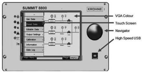
3..1..3 SUMMIT 8800 front panel layout
Figure 1 Front view of Summit 8800
18 |
www.krohne.com |
08/2013 - MA SUMMIT 8800 Vol1 R02 en |
|
DESCRIPTION |
|
SUMMIT 8800 |
03 |
|
|
|
|
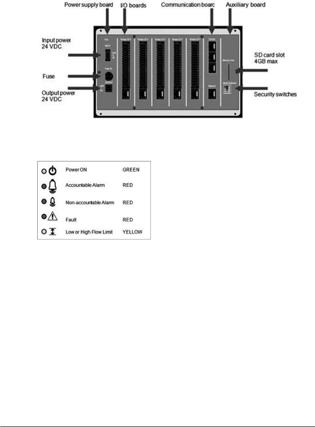
3..1..4 Rear Panel Layout
Figure 2 Rear view of SUMMIT 8800
3..1..5 Alarms & LED’s
Figure 3 LED indicators
Power ON
This indicates that the SUMMIT 8800 is receiving an input power and is operating.
Accountable Alarm
These are alarms that need direct action because they could have effect on the result of the calculations.
Accountable alarms are red and can be defined via the Configurator under stream n.
These are user defined values set within variable parameters such as temperature, pressure, density. Within each run, the user can configure the minimum and maximum value for the variable operating range. This alarm typically indicates that the full operating range has been reached.
Non-accountable Alarm
These are user defined values set within variable parameters such as temperature, pressure, density. Within each run, the user can configure the high and low value for the variable operating range which typically is always less than the maximum and minimum values entered. This alarm typically indicates that the desirable operating range is being exceeded.
08/2013 - MA SUMMIT 8800 Vol1 R02 en |
www.krohne.com |
19 |
|
DESCRIPTION |
|
03 |
SUMMIT 8800 |
|
|
|
|
NOTE: These values (Max, Min, Hi and Lo) can be placed into a security display, where they can be accessed by the “Edit” mode on the SUMMIT 8800.
Fault
Operational self-checking status..
In normal operation the self-checking routine, tests all memory components for data corruption. The watchdog circuit is also provided to detect a failure on the processor.
Faults will also be indicated for each board slot that contains a board that is either faulty, missing a critical board or the wrong type of board.
In case of a fault the LED will illuminate and all calculations will stop – an indication that a hardware error has been detected, that has affected the operation of the flow computer.
Flow Limits
An alarm that indicates that the user-defined low and high flow limits have been reached. These limits are expressed as a percentage of the maximum and minimum flow rate, and are typically lower than the maximum and minimum values.
Flow alarm will come on when the uncorrected flow is above the HiQ value (% of the max flow rate) or below LoQ (% of the maximum flow rate).
When an alarm occurs, the yellow LED will illuminate.
The HiQ is an accountable alarm and the LoQ is a non-accountable alarm.
Further details on how to set these parameters are explained in Volume 2.
3..1..6 Description of Hardware memory devices
The SUMMIT 8800 contains the following types of hardware memory storage devices which are integrated on the board and cannot be removed from the unit.
Flash Memory
•Used to store the operating program (legally relevant software) of the device
•Non-volatile memory requires no power source to maintain integrity of data.
•Can only be externally accessed (Read or Write) when the unit is in the boot mode for programming. This mode can only be accessed when a hardware switch seal is broken and removed.
•Requires unique software tool to download and upload the program file via the USB port.
•Cannot be accessed using any common software tools.
•Integrity of program is maintained by the use of a CRC32 checksum.
Data Flash Memory (Configuration Data)
•Used to store all configuration and set-up parameters (legally relevant parameters).
•Non-volatile memory requires no power source to maintain integrity of data.
•Can only be externally written to when in open security mode. This mode can only be entered when a hardware switch seal is broken and removed.
•Requires unique software tool to download and write the program file via the USB or ethernet port
•Cannot be accessed using any common software tools.
•Integrity of data is maintained by the use of a CRC32 checksum.
Data Flash Memory (Recorded Data)
•Used to store all data log parameters
•Used to store all audit trail data and parameters
20 |
www.krohne.com |
08/2013 - MA SUMMIT 8800 Vol1 R02 en |
|
DESCRIPTION |
|
SUMMIT 8800 |
03 |
|
|
|
|
•Used to store all alarm record data and parameters
•Non-volatile memory requires no power source to maintain integrity of data.
•Cannot be written to from any external source: it is read only memory.
•Requires unique software tool to upload the data files via the USB or ethernet port
•Cannot be accessed using any common software tools.
•Integrity of each individual data, audit or alarm record is maintained by the use of a recorded time stamp and an individual CRC32 checksum for each individual record.
Static RAM Memory (Recorded Data)
•Used to store calculation results. Data that can change on every calculation cycle, e.g. flow measurement totals and parameter averages.
•Non-volatile memory that requires internal lithium back-up battery to maintain integrity of data.
•Backup battery is integrated inside the unit and cannot be switched off or removed without breaking a hardware seal and removing the rear panel of the unit.
•Backup battery capacity is sufficient to maintain data for at least 5 years of normal operation.
•Backup battery condition is continuously monitored and indication is given when replacement is due.
•Cannot be written to from any external source: it is read only memory.
•Requires a unique software tool to upload the data files via the USB port or ethernet port
•Cannot be accessed using any common software tools.
•Integrity of the data is maintained by the use of duplicate records for each value which are verified against individual CRC32 checksums for each individual record block.
The SUMMIT 8800 also contains the following types of optional hardware memory storage devices which are integrated in the design of the SUMMIT 8800 but can be removed from the unit.
SD memory Card
•Used to store data log parameters (separate from data logs stored in data flash memory)
•Up to 4GB of data storage or typically lifetime storage.
•Used to store all audit trail data and parameters (duplicate copy of audit trail data stored in data flash memory)
•Non-volatile memory requires no power source to maintain integrity of data.
•Cannot be written to from any external source: it has an internal coding.
•Requires a unique software tool to upload the data files via the USB or ethernet port or via a SD slot in a PC
•Cannot be accessed using any common software tools.
•Integrity of each individual data, audit or alarm record is maintained by the use of a recorded time stamp and an individual CRC32 checksum for each individual record.
•Can be removed from the unit at any time.
3..2 Features SUMMIT 8800
3..2..1 Key Features
•Touch screen
•VGA colour graphics & Navigator dial.
•Multi-processing makes the unit 10-50x faster than traditional flow computers
•50-2000 times more memory
•Years of data storage
•More accuracy due to more frequent calculations
•Modular design hardand software, Pay only for what is needed
•Up to 6+ runs, Affordable for allocation metering
•Supervisory like functions, More capabilities for lower price
•Audit trail up to person
•Network capabilities, Metering info available centrally
08/2013 - MA SUMMIT 8800 Vol1 R02 en |
www.krohne.com |
21 |
|
DESCRIPTION |
|
03 |
SUMMIT 8800 |
|
|
|
|
•Pulse handling: API5.5 level A, B, C, D, E, Dual chronometry, pulse interpolation
•Calibration up to 20 points linear, meter factor or K-curve, 5 products (future at present 1)
•Density/ specific gravity: frequencies Solartron 781x, 783x, Sarasota ID900
•Counters: Unhaltable, Normal, Period, Error, Maintenance, Positive and negative, Prover
•Averages: Time weighted, Flow weighted.
•Provers: Bi-directional, 2 / 4 detector inputs, piston prover, master provers
•Control: up to 18 valves, Prover, PID
•TCP/IP and serial Modbus protocols for
Ultrasonic meters: KROHNE AIII, AV, V12, Daniel, Elster, GE, Sick Chromatographs: ABB, Daniel, Elster, Siemens
•And custom configurable protocols.
3..2..2 Calculations & Compliance standards
AGA3 |
(Orifice meters) gas flow calculations. |
|
|
|
|
AGA5 |
(Natural Gas Energy Measurement) |
|
|
|
|
AGA7 |
(Measurement of Natural Gas by Turbine Meter) |
|
|
|
|
AGA8 |
(Compressibility Factor of Natural Gas and Related Hydrocarbon Gases) |
|
|
|
|
AGA9-support |
(Measurement of Gas by Multipath Ultrasonic Meters) |
|
|
|
|
AGA10 |
(Speed of Sound in Natural Gas and Other Related Hydrocarbon Gases) |
|
API MPMS (Manual of |
Chapter 5.6 (Measurement of Liquid Hydrocarbons by Coriolis Meters) |
|
Petroleum Measurement |
|
|
Chapters 11.1, 11.2, 21.1 & 21.2 etc |
||
Standards): |
||
|
||
Chapters 12.2.5.1 & 2 |
||
|
||
|
|
|
|
Chapter 12.2.5.3 Table 54, 54A, 54B, 54D |
|
|
|
|
API 2540 |
|
|
|
|
|
ASTM D1250 IP200 |
|
|
GPA 2172, TP-27 |
|
|
|
|
|
GOST NX19 |
|
|
|
|
|
ISO 5167 (2003 , 1997, 1991) |
|
|
|
|
|
ISO 6976 |
|
|
|
|
|
NX19, NX19 G9 |
|
|
|
|
|
OIML R117-1 Edition 2007 |
|
|
|
|
|
PTZ, NX19, NX19 G9, SGERG |
(all types), User-defined Z-factor Tables, fixed |
|
|
|
|
SGERG |
(all types) |
|
|
|
|
WELMEC guide 8.8 |
|
|
|
|
... and more to come
3..3 Integration possibilities
3..3..1 System Integration
The SUMMIT 8800 can be integrated as a component within a fully automated system.
When within a system, the SUMMIT 8800 is usually an intermediate device interacting with all field devices and supervisory systems.
22 |
www.krohne.com |
08/2013 - MA SUMMIT 8800 Vol1 R02 en |
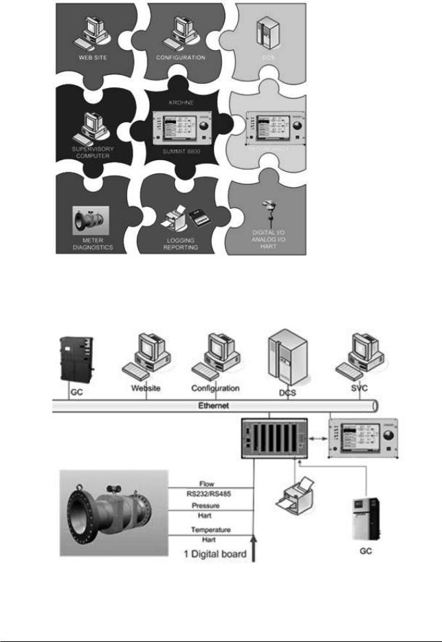
|
DESCRIPTION |
|
SUMMIT 8800 |
03 |
|
|
|
|
Figure 4 SUMMIT 8800 system integration overview
3..3..2 Application integration
Figure 5 Stream application integration |
|
|
08/2013 - MA SUMMIT 8800 Vol1 R02 en |
www.krohne.com |
23 |
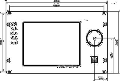
|
INSTALLATION AND REPLACEMENT |
|
04 |
SUMMIT 8800 |
|
|
|
|
Please read these instructions carefully before assembling or installing this product to avoid danger to people, pets and damage to connecting devices and the SUMMIT 8800. Installation of this product may only be performed by qualified personnel.
The SUMMIT 8800 comes with all links and internal switches set to factory default see Chapter Hardware Details: Rear panel Mode Switches.
Before any power or signal connections are applied to the SUMMIT 8800 the qualified personnel should ensure that all links are set at the correct position for the appropriate and intended use. Failure to do so may result in damage to the SUMMIT 8800 and any associated equipment.
The flow computer device is powered with +24VDC.
Do not touch any of the internal components whilst the unit is powered.
Turn off the power to the SUMMIT 8800 before opening the device or installing the product. Only energize the device when it is wired, installed and all covers are securely in place.
4..1 Mechanical Specifications
4..1..1 Mechanical Installation
All installation tasks should be performed by qualified personnel. The external chassis dimensions (for panel or rack mounting) are given in the figure below. Ensure that the ventilation slots on the upper and lower surfaces on the SUMMIT 8800 are kept clear from any obstruction. Ensure that ventilation and shading is provided when the SUMMIT 8800 is subjected to high ambient temperatures (such as being near heat producing apparatus) or to direct sunlight. The operating environment must be clean, dry and free from corrosive elements.
NOTE: When used as part of MID approval which states the use of the SUMMIT 8800 to be indoors and in a controlled environment where it is subject to the requirements of EN 12405, the SUMMIT 8800 must be mounted in an enclosure with an ingress protection rating of IP65 or better.
Front
24 |
www.krohne.com |
08/2013 - MA SUMMIT 8800 Vol1 R02 en |
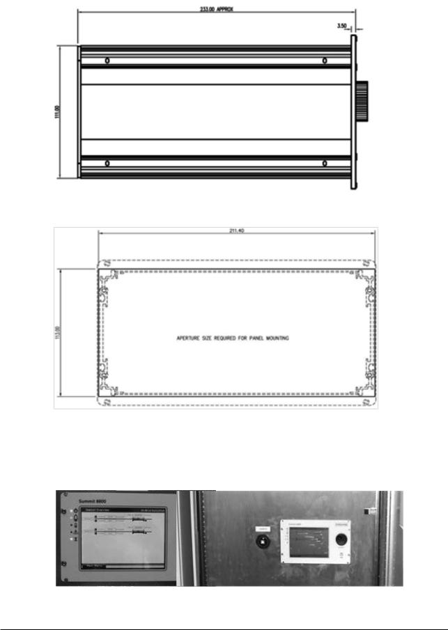
|
INSTALLATION AND REPLACEMENT |
|
SUMMIT 8800 |
04 |
|
|
|
|
Side
Panel cut-out
Figure 6 Dimensions & Outlines
4..1..2 Panel Mounting
Figure 7 Panel mounted installations
08/2013 - MA SUMMIT 8800 Vol1 R02 en |
www.krohne.com |
25 |
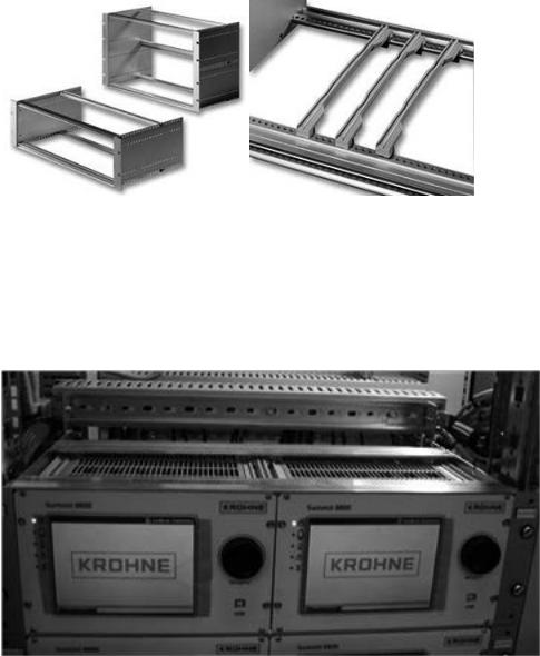
|
INSTALLATION AND REPLACEMENT |
|
04 |
SUMMIT 8800 |
|
|
|
|
The SUMMIT 8800 can be mounted in a panel. For this, use the dimensions for the panel cut-out as described in the previous paragraph. Please note that the SUMMIT 8800 is fixed to the panel using the bolts on top and bottom of the SUMMIT 8800.
4..1..3 Rack mounting options
For the SUMMIT 8800 optional rack mounting kits are available to ease cabinet, rack or panel installation. Please consult your local KROHNE sales department or major suppliers such as Farnell and Rittal.
Figure 8 Rack mounting kit
Ordering code:
Rittal |
RP 3688115 Subrack RIPAC ECO 3Ux235 |
|
|
Farnell |
3688115 - SUBRACK, ECO, 3U, 235MM, 84HP 1198862 |
|
|
RS components |
PCB guide kit, 500-566 (4*) |
|
|
Figure 9 Rack mounted installation
4..1..4 Cable Assembly
For rack mounted installations, a 2.5m rail mounted terminal cable loom assembly is available for the SUMMIT 8800 flow computer.
26 |
www.krohne.com |
08/2013 - MA SUMMIT 8800 Vol1 R02 en |

|
INSTALLATION AND REPLACEMENT |
|
SUMMIT 8800 |
04 |
|
|
|
|
Figure 10 Cable assembly
4..2 Electrical Specifications
4..2..1 Electrical Installation
The SUMMIT 8800 is certified to be in compliance with IEC 61010-1:2001 provided it is installed in accordance with the instructions supplied.
The SUMMIT 8800 must be powered by:
A Class 2 power supply is defined by article 725.41 of the National Electrical Code (NEC Code book) and has limited output power.
In addition the wiring between the SUMMIT 8800 and its power supply must be sufficiently rated (10A) with a minimum cross section area of 1.5mm2 and PVC insulation. A suitable rated switch or circuit breaker must be included to allow isolation of power supply to the SUMMIT 8800. The device should be mounted as near to the equipment as practically possible.
No routine maintenance is required to ensure continuous operation; however, should a system failure occur during operations, then the most likely cause of malfunction is that of a requirement not being fully or correctly implemented. If a fault or warning occurs, the cause should be determined in a logical and systematic manner following the guide given below. All maintenance tasks should be carried out by qualified personnel only.
08/2013 - MA SUMMIT 8800 Vol1 R02 en |
www.krohne.com |
27 |

|
INSTALLATION AND REPLACEMENT |
|
04 |
SUMMIT 8800 |
|
|
|
|
Some parts of the instrument such as circuit boards may be damaged by static electricity. When handling internal parts of the instruments, ensure that anti-static precautions are taken. It is therefore essential when carrying out any maintenance or installation work that an earthed wrist strap be worn, or other such precautions, whenever internal parts of the instrument are handled.
4..2..2 Earthing Requirements
The SUMMIT 8800 must be connected to a suitable ground or earth connection via the M4 earth stud located at the rear of the chassis. See below for details.
4..2..3 Fuses and Battery
The SUMMIT 8800 has an internal fuse F1 and an externally accessible fuse F2 on the rear panel. Fuse F1 protects the DC input circuits and can only be replaced by qualified personnel. Isolate the main power to the SUMMIT 8800. Remove the rear panel as specified under Hardware Details. Withdraw the PSU board and identify F1 as detailed in the figure below. Replace fuse F1 only with a replacement fuse type:
Fuse F2 protects the DC output and can be replaced by all personnel. Isolate the main power
28 |
www.krohne.com |
08/2013 - MA SUMMIT 8800 Vol1 R02 en |
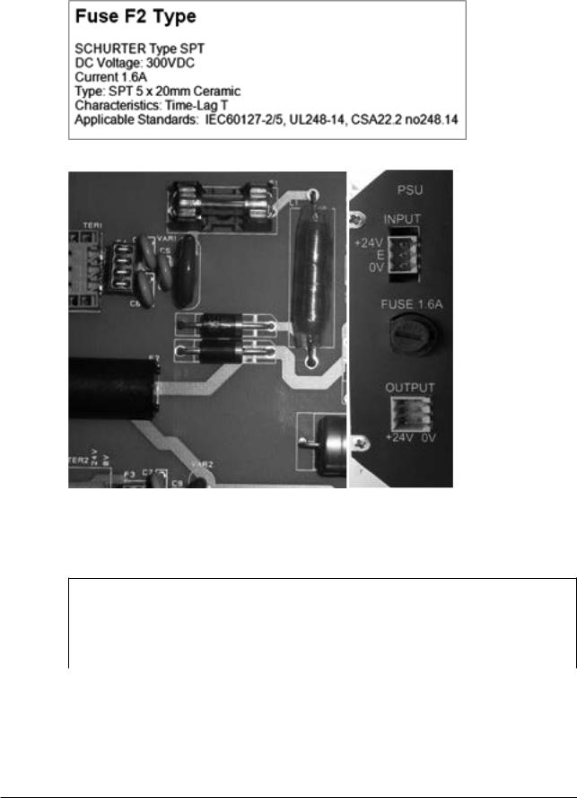
|
INSTALLATION AND REPLACEMENT |
|
SUMMIT 8800 |
04 |
|
|
|
|
to the Flow Computer SUMMIT 8800. Rotate the cap of fuse holder F2 counter clockwise and replace fuse F2 only with a replacement fuse type:
Figure 11 Fuse F1 (left) en F2 (right)
4..2..4 Power Supply Terminals
POWER SUPPLY INPUT CONNECTOR TER 1
Terminal |
FUNCTION |
|
1 |
+24V DC |
+24V DC positive power supply Terminal |
|
|
|
2 |
E |
Earth connection terminal |
|
|
|
3 |
0V |
Power Supply 0V terminal |
|
|
|
|
|
|
AUXILIARY POWER SUPPLY OUTPUT CONNECTOR TER 2 |
||
|
|
|
Terminal |
FUNCTION |
|
|
|
|
1 |
+24V DC |
+24V DC Auxiliary output supply |
|
|
|
2 |
+24V DC |
+24V DC Auxiliary output supply |
|
|
|
3 |
+24V DC |
+24V DC Auxiliary output supply I max = 200mA |
08/2013 - MA SUMMIT 8800 Vol1 R02 en |
www.krohne.com |
29 |
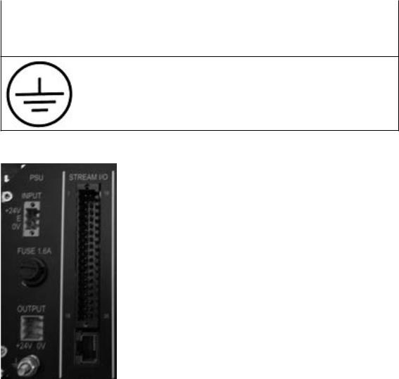
|
INSTALLATION AND REPLACEMENT |
|
04 |
SUMMIT 8800 |
|
|
|
|
4 |
0V |
0V Auxiliary output supply |
|
|
|
5 |
0V |
0V Auxiliary output supply |
6 |
0V |
0V Auxiliary output supply |
|
|
|
CHASSIS EARTH SCREW TERMINAL
Earth stud terminal M4
Figure 12 Power & M4 earth connections
4..2..5 Back Up Battery
The SUMMIT 8800 contains a backup battery on the auxiliary card, this battery keeps the real time clock and internal totals when DC power to the unit is disconnected. Replacement of this battery should only be carried out by qualified personnel.
If the SUMMIT 8800 is kept continuously powered, the back-up battery estimated life is 10 years. If the SUMMIT 8800 is powered down for periods exceeding 30 days, the battery should be removed and stored separately. The battery needs to be replaced when its service life exceeds 10 years or when it has been left in an un-powered unit for a time period of greater than 2 months. A “BAD” battery condition is indicated via the Windows software.
When a “BAD” battery condition is indicated via the Windows software or on the front panel:
30 |
www.krohne.com |
08/2013 - MA SUMMIT 8800 Vol1 R02 en |
 Loading...