


PH8150
Digital pH sensor for the chemical industry
Electronic Revision:
ER 3.3.x
(SW.REV. 1.x.x)
SMARTSENS PH 8150
SMARTSENS PH 8150SMARTSENS PH 8150
SMARTSENS PH 8150
Handbook
HandbookHandbook
Handbook
© KROHNE 11/2013 - 4002543602 - MA SMARTSENS PH 8150 R02 en

All rights reserved. It is prohibited to reproduce this documentation, or any part thereof, without
the prior written authorisation of KROHNE Messtechnik GmbH.
Subject to change without notice.
2
SMARTSENS PH 8150
www.krohne.com 11/2013 - 4002543602 - MA SMARTSENS PH 8150 R02 en
Copyright 2013 by
KROHNE Messtechnik GmbH - Ludwig-Krohne-Str. 5 - 47058 Duisburg (Germany)
: IMPRINT :::::::::::::::::::::::::::::::::::::::

CONTENTS
3
www.krohne.com11/2013 - 4002543602 - MA SMARTSENS PH 8150 R02 en
SMARTSENS PH 8150
1 Safety instructions 5
1.1 Intended use ..................................................................................................................... 5
1.2 Safety instructions from the manufacturer ..................................................................... 5
1.2.1 Copyright and data protection ................................................................................................ 5
1.2.2 Disclaimer ............................................................................................................................... 6
1.2.3 Product liability and warranty ................................................................................................ 6
1.2.4 Information concerning the documentation........................................................................... 6
1.2.5 Warnings and symbols used................................................................................................... 7
1.3 Safety instructions for the operator................................................................................. 7
2 Device description 8
2.1 Scope of delivery............................................................................................................... 8
2.2 Device description ............................................................................................................ 9
2.2.1 pH sensor ................................................................................................................................9
2.3 Nameplate ...................................................................................................................... 10
3 Installation 11
3.1 General notes on installation ......................................................................................... 11
3.2 Storage and transport .................................................................................................... 11
3.3 Installation procedure .................................................................................................... 12
3.4 Pre-installation requirements ....................................................................................... 12
3.5 Electrical connection......................................................................................................13
3.5.1 Connecting the cable to the sensor...................................................................................... 13
3.5.2 Connecting the sensor cable ................................................................................................ 14
3.5.3 Connecting with junction box SJB 200 W.............................................................................. 14
3.6 Installing the sensor....................................................................................................... 16
3.6.1 General installation instructions.......................................................................................... 16
4 Operation 17
4.1 Calibration ...................................................................................................................... 17
4.1.1 Calibration with PACTware
TM........................................................................................................................ 17
4.1.2 Calibration with HART
®
Handheld 475 FIELD COMMUNICATOR ........................................ 19
4.2 Troubleshooting.............................................................................................................. 22
4.3 Status messages and diagnostic information................................................................ 23
5 Service 24
5.1 Maintenance ................................................................................................................... 24
5.1.1 Cleaning ................................................................................................................................ 24
5.1.2 Aging and re-calibration ....................................................................................................... 24
5.2 Availability of services .................................................................................................... 25
5.3 Returning the device to the manufacturer..................................................................... 26
5.3.1 General information.............................................................................................................. 26
5.3.2 Form (for copying) to accompany a returned device............................................................ 27
5.4 Disposal .......................................................................................................................... 27

CONTENTS
4
www.krohne.com 11/2013 - 4002543602 - MA SMARTSENS PH 8150 R02 en
SMARTSENS PH 8150
6 Technical data 28
6.1 Measuring principle........................................................................................................28
6.1.1 pH measurement .................................................................................................................. 28
6.2 Technical data................................................................................................................. 30
6.3 Dimensions ..................................................................................................................... 32
7 Description of HART interface 33
7.1 General description ........................................................................................................33
7.2 Software history ............................................................................................................. 33
7.3 Connection variants........................................................................................................34
7.3.1 Point-to-Point connection - analogue / digital mode........................................................... 35
7.4 Inputs/outputs and HART
®
dynamic variables and device variables............................ 36
7.5 Field Communicator 475 (FC 475).................................................................................. 36
7.5.1 Installation ............................................................................................................................ 36
7.6 Field Device Tool / Device Type Manager (FDT/DTM).................................................... 37
7.6.1 Installation ............................................................................................................................ 37
7.7 Overview Basic-DD menu tree (positions in menu tree) ............................................... 37
7.8 Basic-DD menu tree (details for settings) ..................................................................... 38
8 Appendix 41
8.1 pH as a function of mV.................................................................................................... 41
8.2 pH temperature dependency.......................................................................................... 42
SAFETY INSTRUCTIONS 1
5
SMARTSENS PH 8150
www.krohne.com11/2013 - 4002543602 - MA SMARTSENS PH 8150 R02 en
1.1 Intended use
The intended use of the sensor SMARTSENS PH 8150 is the measurement of pH in liquids.
1.2 Safety instructions from the manufacturer
1.2.1 Copyright and data protection
The contents of this document have been created with great care. Nevertheless, we provide no
guarantee that the contents are correct, complete or up-to-date.
The contents and works in this document are subject to copyright. Contributions from third
parties are identified as such. Reproduction, processing, dissemination and any type of use
beyond what is permitted under copyright requires written authorisation from the respective
author and/or the manufacturer.
The manufacturer tries always to observe the copyrights of others, and to draw on works created
in-house or works in the public domain.
The collection of personal data (such as names, street addresses or e-mail addresses) in the
manufacturer's documents is always on a voluntary basis whenever possible. Whenever
feasible, it is always possible to make use of the offerings and services without providing any
personal data.
We draw your attention to the fact that data transmission over the Internet (e.g. when
communicating by e-mail) may involve gaps in security. It is not possible to protect such data
completely against access by third parties.
We hereby expressly prohibit the use of the contact data published as part of our duty to publish
an imprint for the purpose of sending us any advertising or informational materials that we have
not expressly requested.
DANGER!
For devices used in hazardous areas, additional safety notes apply; please refer to the Ex
documentation.
CAUTION!
Responsibility for the use of the measuring devices with regard to suitability, intended use and
corrosion resistance of the used materials against the measured fluid lies solely with the
operator.
INFORMATION!
The manufacturer is not liable for any damage resulting from improper use or use for other than
the intended purpose.

1 SAFETY INSTRUCTIONS
6
SMARTSENS PH 8150
www.krohne.com 11/2013 - 4002543602 - MA SMARTSENS PH 8150 R02 en
1.2.2 Disclaimer
The manufacturer will not be liable for any damage of any kind by using its product, including,
but not limited to direct, indirect or incidental and consequential damages.
This disclaimer does not apply in case the manufacturer has acted on purpose or with gross
negligence. In the event any applicable law does not allow such limitations on implied warranties
or the exclusion of limitation of certain damages, you may, if such law applies to you, not be
subject to some or all of the above disclaimer, exclusions or limitations.
Any product purchased from the manufacturer is warranted in accordance with the relevant
product documentation and our Terms and Conditions of Sale.
The manufacturer reserves the right to alter the content of its documents, including this
disclaimer in any way, at any time, for any reason, without prior notification, and will not be liable
in any way for possible consequences of such changes.
1.2.3 Product liability and warranty
The operator shall bear responsibility for the suitability of the device for the specific purpose.
The manufacturer accepts no liability for the consequences of misuse by the operator. Improper
installation and operation of the devices (systems) will cause the warranty to be void. The
respective "Standard Terms and Conditions" which form the basis for the sales contract shall
also apply.
1.2.4 Information concerning the documentation
To prevent any injury to the user or damage to the device it is essential that you read the
information in this document and observe applicable national standards, safety requirements
and accident prevention regulations.
If this document is not in your native language and if you have any problems understanding the
text, we advise you to contact your local office for assistance. The manufacturer can not accept
responsibility for any damage or injury caused by misunderstanding of the information in this
document.
This document is provided to help you establish operating conditions, which will permit safe and
efficient use of this device. Special considerations and precautions are also described in the
document, which appear in the form of underneath icons.
SAFETY INSTRUCTIONS 1
7
SMARTSENS PH 8150
www.krohne.com11/2013 - 4002543602 - MA SMARTSENS PH 8150 R02 en
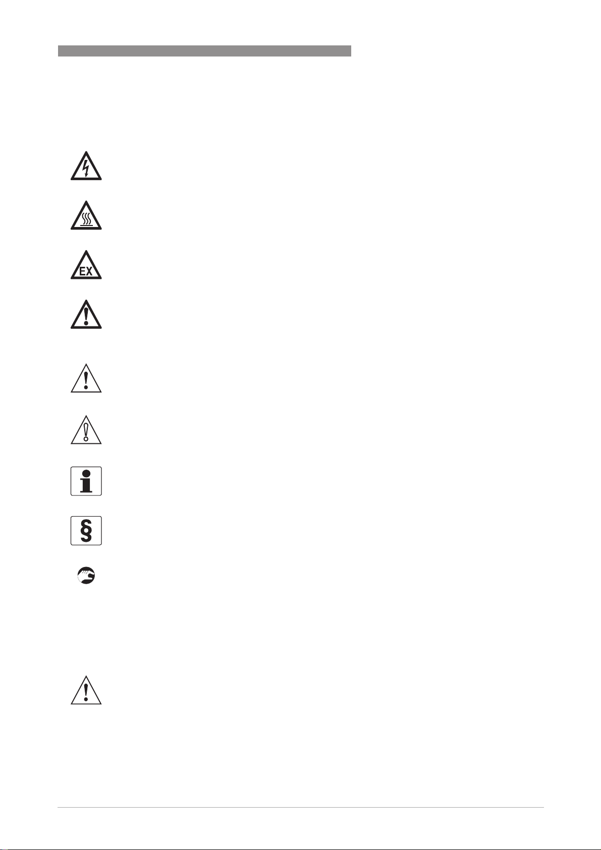
1.2.5 Warnings and symbols used
Safety warnings are indicated by the following symbols.
• HANDLING
HANDLINGHANDLING
HANDLING
This symbol designates all instructions for actions to be carried out by the operator in the
specified sequence.
i RESULT
RESULTRESULT
RESULT
This symbol refers to all important consequences of the previous actions.
1.3 Safety instructions for the operator
DANGER!
This information refers to the immediate danger when working with electricity.
DANGER!
This warning refers to the immediate danger of burns caused by heat or hot surfaces.
DANGER!
This warning refers to the immediate danger when using this device in a hazardous atmosphere.
DANGER!
These warnings must be observed without fail. Even partial disregard of this warning can lead to
serious health problems and even death. There is also the risk of seriously damaging the device
or parts of the operator's plant.
WARNING!
Disregarding this safety warning, even if only in part, poses the risk of serious health problems.
There is also the risk of damaging the device or parts of the operator's plant.
CAUTION!
Disregarding these instructions can result in damage to the device or to parts of the operator's
plant.
INFORMATION!
These instructions contain important information for the handling of the device.
LEGAL NOTICE!
This note contains information on statutory directives and standards.
WARNING!
In general, devices from the manufacturer may only be installed, commissioned, operated and
maintained by properly trained and authorized personnel.
This document is provided to help you establish operating conditions, which will permit safe and
efficient use of this device.
2 DEVICE DESCRIPTION
8
SMARTSENS PH 8150
www.krohne.com 11/2013 - 4002543602 - MA SMARTSENS PH 8150 R02 en
2.1 Scope of delivery
Optional accessories
• SENSOFIT FLOW 1000 series - Flow-through assemblies
• SENSOFIT IMM 1000 / 2000 series - Immersion assemblies
• SENSOFIT INS 1000 / 7000 series - Insertion assemblies
• SENSOFIT RET / RAM 5000 series - Manual and pneumatic retractable assemblies
• SMARTSENS cable VP 2.0 (various lengths)
• SMARTMAC 200 W - Wall mount display with calibration and configuration functions
• SD 200 W/R - Wall or rack mount indicator
• SMARTBRIDGE - USB interface cable
• SJB 200 W - Junction box
Consumables/Spare parts available
• pH buffer solutions for sensor calibration
• Various cleaning solutions
INFORMATION!
Inspect the cartons carefully for damages or signs of rough handling. Report damage to the
carrier and to the local office of the manufacturer.
INFORMATION!
Do a check of the packing list to make sure that you have all the elements given in the order.
INFORMATION!
Look at the device nameplate to ensure that the device is delivered according to your order.
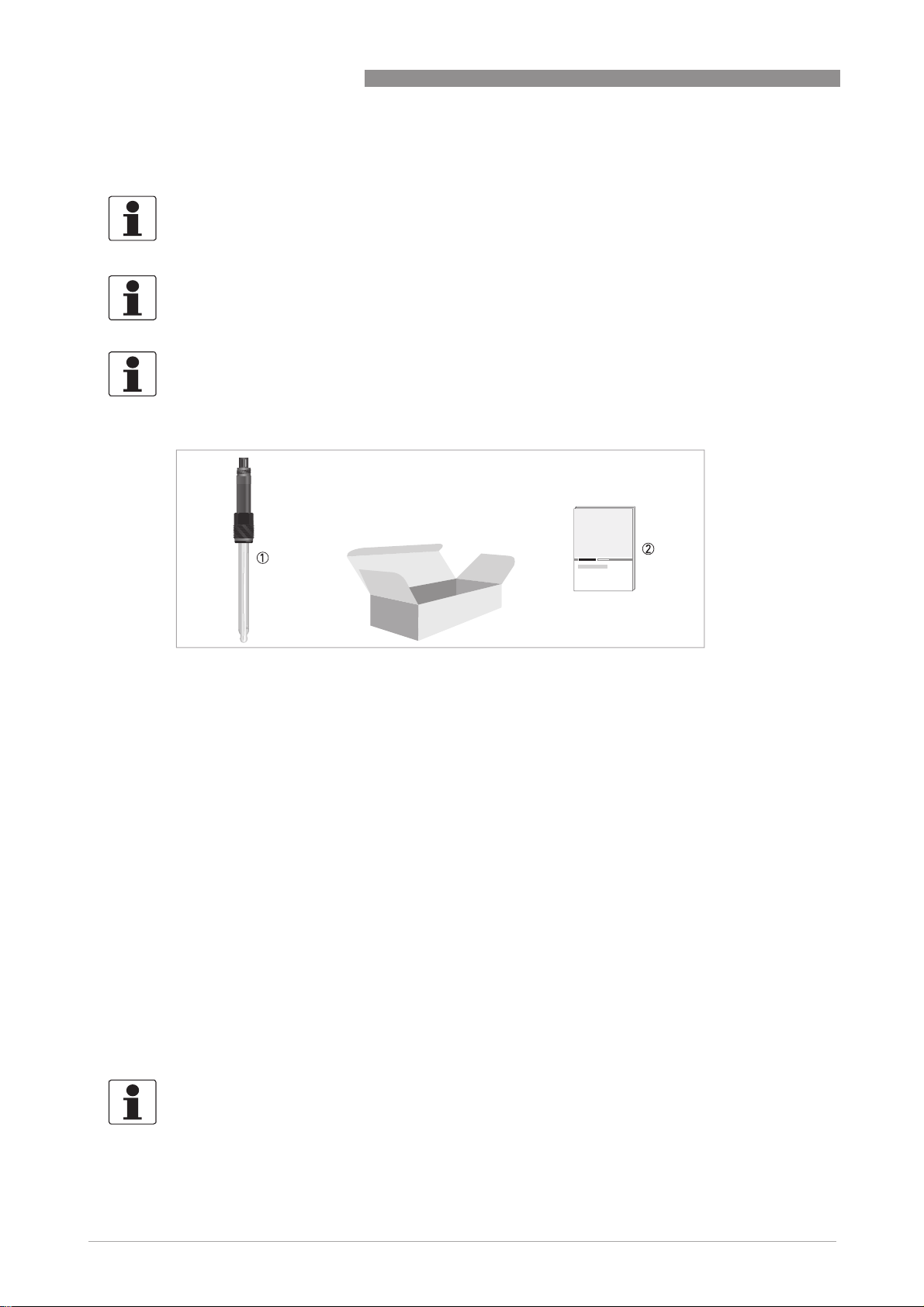
Figure 2-1: Standard scope of delivery
1 Ordered sensor
2 Documentation
INFORMATION!
For further information contact your local sales office.
DEVICE DESCRIPTION 2
9
SMARTSENS PH 8150
www.krohne.com11/2013 - 4002543602 - MA SMARTSENS PH 8150 R02 en
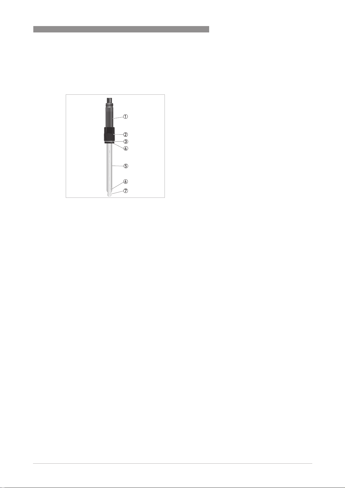
2.2 Device description
2.2.1 pH sensor
Figure 2-2: Construction of the sensor
1 Nickel plated brass body with VP 2.0 connector or
PEEK body with VP 2.0 connector (in preparation)
2 PG 13.5 thread
3 Washer
4 O-ring
5 Glass shaft
6 Diaphragm
7 Membrane glass
2 DEVICE DESCRIPTION
10
SMARTSENS PH 8150
www.krohne.com 11/2013 - 4002543602 - MA SMARTSENS PH 8150 R02 en
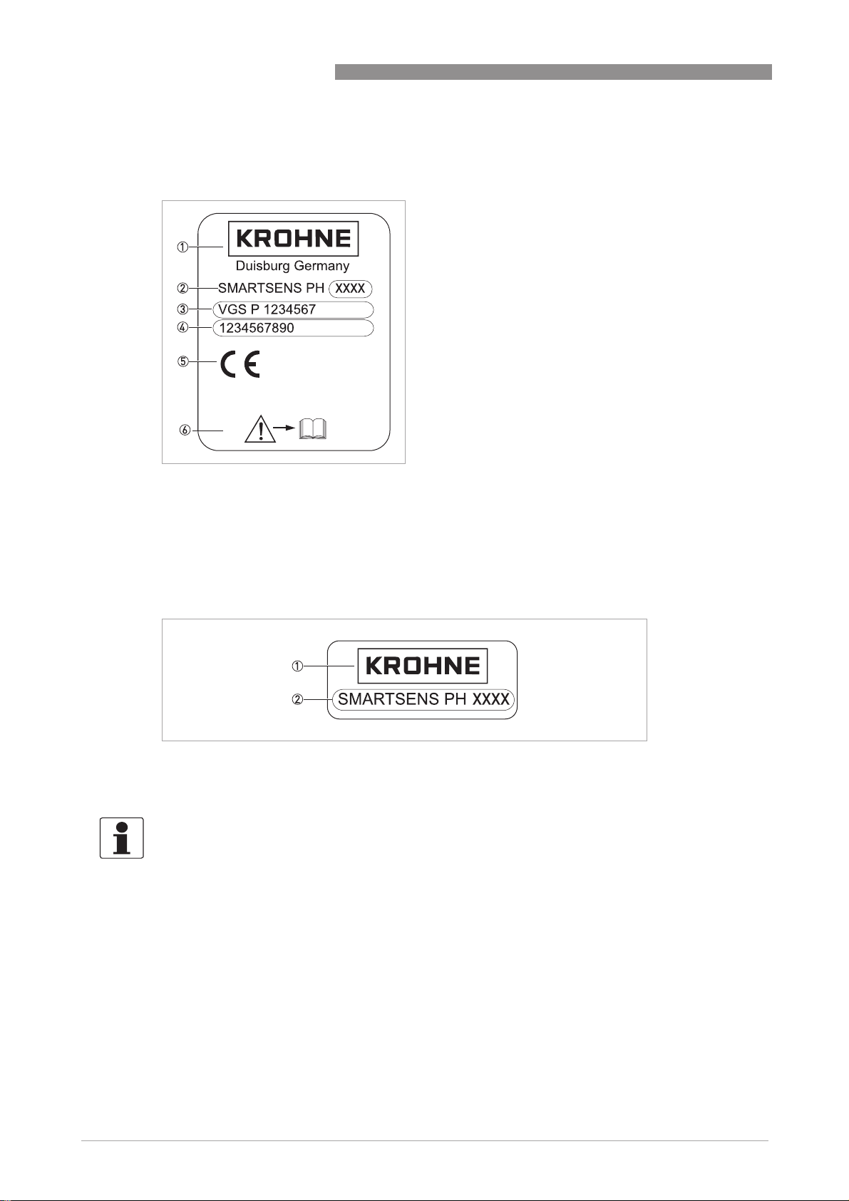
2.3 Nameplate
The sensor type is specified on the label of the sensor package and on the sensor itself.
Figure 2-3: Example for a nameplate on the sensor body
1 Manufacturer
2 Device name
3 Order code
4 Serial number
5 Approvals
6 Observe the operation and installation instruction
Figure 2-4: Example for a nameplate on the glass shaft
1 Manufacturer
2 Device name
INFORMATION!
Look at the device nameplate to ensure that the device is delivered according to your order.
INSTALLATION 3
11
SMARTSENS PH 8150
www.krohne.com11/2013 - 4002543602 - MA SMARTSENS PH 8150 R02 en
3.1 General notes on installation
3.2 Storage and transport
• Since the pH sensor is made out of glass it is very fragile. Avoid shocks of any kind.
• Do not touch or scratch the membrane glass.
• Store the sensor in its original packaging in a dry, dust-free location. Keep it away from dirt. If
necessary, clean it as described on page 24.
DANGER!
For devices used in hazardous areas, additional safety notes apply; please refer to the Ex
documentation.
DANGER!
All work on the electrical connections may only be carried out with the power disconnected.
DANGER!
Observe the national regulations for electrical installations!
WARNING!
During installation of the device make sure that you use ESD (electronic discharge) protection
equippment.
WARNING!
Observe without fail the local occupational health and safety regulations. Any work done on the
electrical components of the measuring device may only be carried out by properly trained
specialists.
INFORMATION!
Inspect the cartons carefully for damages or signs of rough handling. Report damage to the
carrier and to the local office of the manufacturer.
INFORMATION!
Do a check of the packing list to make sure that you have all the elements given in the order.
INFORMATION!
Look at the device nameplate to ensure that the device is delivered according to your order.
CAUTION!
Do not store the sensor tip dry. This will shorten lifetime considerably.
Always store the pH sensor tip wet in a 3 molar KCl solution when not in use. Saltless water
must be avoided since this would leak the KCl ions. The original packing in which the sensor tip
was delivered contains a plastic tube with KCl solution and therefore is suitable for storage and
transport.
3 INSTALLATION
12
SMARTSENS PH 8150
www.krohne.com 11/2013 - 4002543602 - MA SMARTSENS PH 8150 R02 en
3.3 Installation procedure
Because a new pH sensor needs to be calibrated before it is installed into its final measuring
location, it is important to follow the installation order:
1 Unpack the sensor.
2 Connect the sensor to the junction box or directly to the process control system.
3 Calibrate the sensor.
4 Install the sensor into its final measuring location.
The required steps are explained in the following sections.
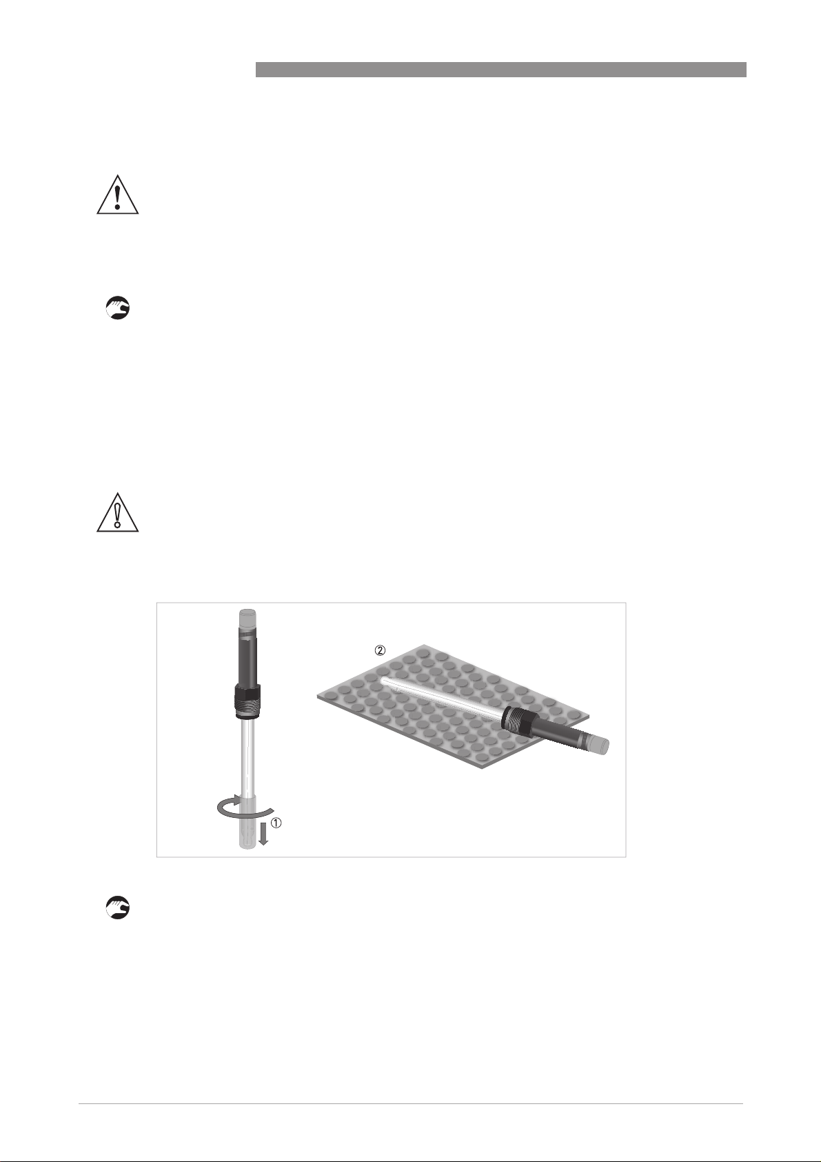
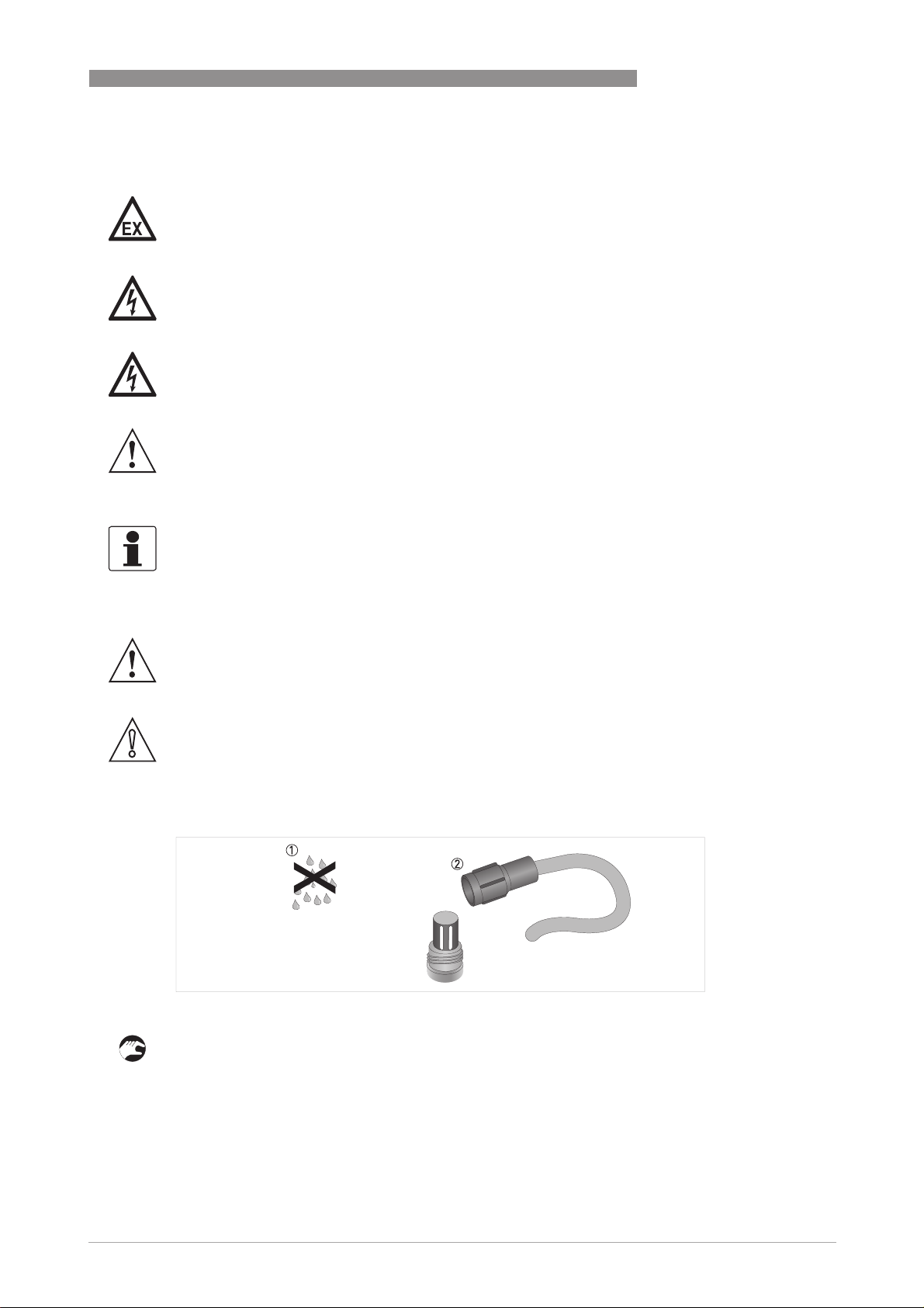
3.4 Pre-installation requirements
Unpacking the sensor
• Remove by gently twisting and pulling the protective cap from the sensor 1.
• Lay the sensor on a soft mat/tissue 2.
• Leave the protection cap of the VP connector on the connector, as long as the sensor is not
connected to the cable.
WARNING!
During installation of the device make sure that you use ESD (electronic discharge) protection
equippment.
CAUTION!
•
Never touch or scratch the membrane glass of the sensor.
•
Store the sensor in its original packaging in a dry, dust-free location. Keep it away from dirt. If
necessary, clean it as described on page 24
.
Figure 3-1: Unpacking the sensor
INSTALLATION 3
13
SMARTSENS PH 8150
www.krohne.com11/2013 - 4002543602 - MA SMARTSENS PH 8150 R02 en
3.5 Electrical connection
3.5.1 Connecting the cable to the sensor
Connecting the cable to the sensor
• Ensure that both cable and sensor connector are absolutely dry 1.
• Screw the cable connector 2 on the sensor and tighten it by hand.
DANGER!
For devices used in hazardous areas, additional safety notes apply; please refer to the Ex
documentation.
DANGER!
All work on the electrical connections may only be carried out with the power disconnected.
DANGER!
Observe the national regulations for electrical installations!
WARNING!
Observe without fail the local occupational health and safety regulations. Any work done on the
electrical components of the measuring device may only be carried out by properly trained
specialists.
INFORMATION!
Look at the device nameplate to ensure that the device is delivered according to your order.
WARNING!
During installation of the device make sure that you use ESD (electronic discharge) protection
equippment.
CAUTION!
Moisture inside the sensor connector must be avoided! Moisture may cause a shortcut and
deliver erratic readings!
If moisture has entered the connector dry it with air (e.g. hair blower).
Figure 3-2: Connecting the cable to the sensor
3 INSTALLATION
14
SMARTSENS PH 8150
www.krohne.com 11/2013 - 4002543602 - MA SMARTSENS PH 8150 R02 en
3.5.2 Connecting the sensor cable
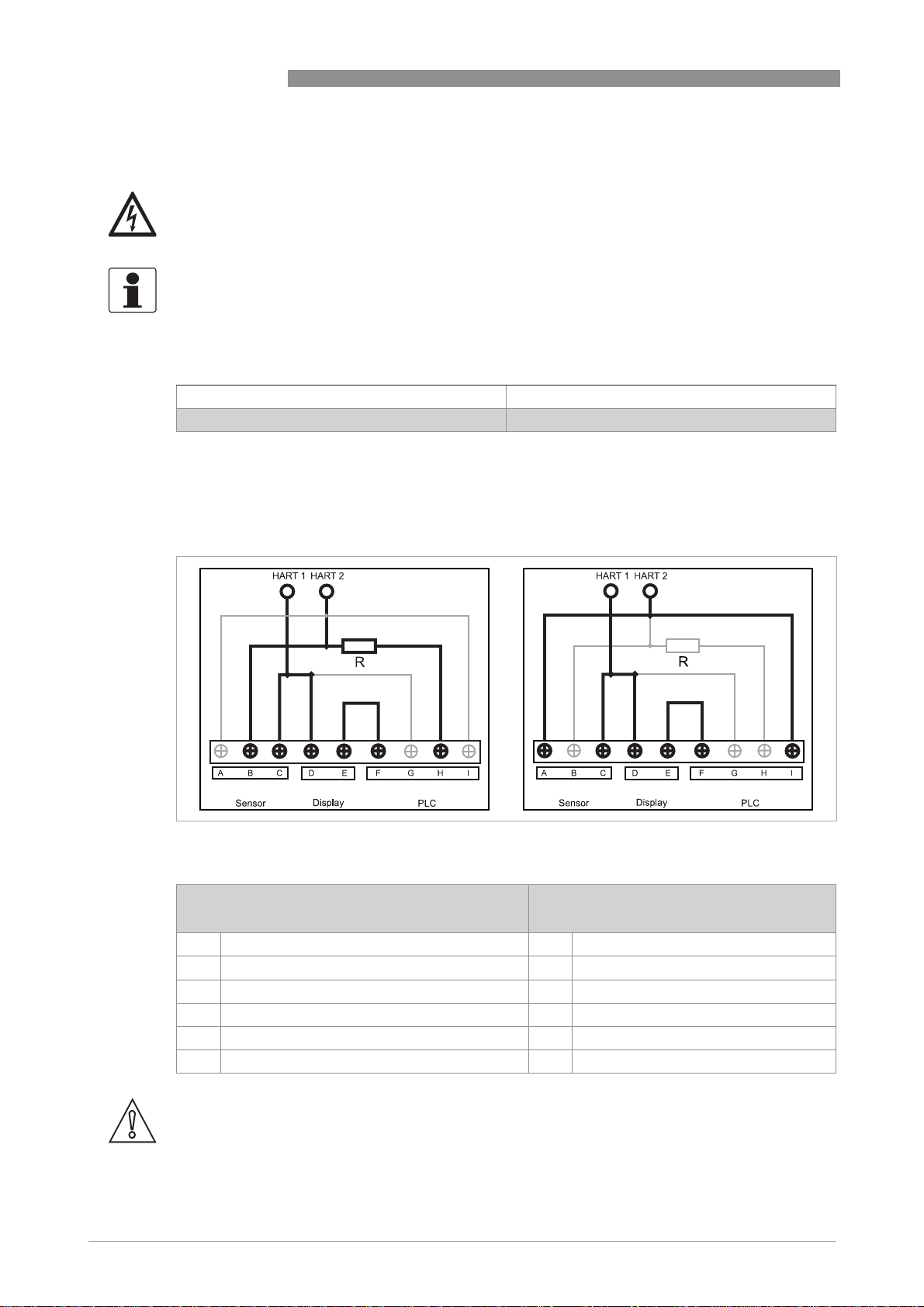
3.5.3 Connecting with junction box SJB 200 W
DANGER!
All work on the electrical connections may only be carried out with the power disconnected.
INFORMATION!
Look at the device nameplate to ensure that the device is delivered according to your order.
SMARTSENS cable VP 2.0
Black (inner coax shield) Ub+
White Ub-
Figure 3-3: SJB 200 W with SMARTMAC 200 W and with resistance R (left side). SJB 200 W with SMARTMAC 200 W and
without resistance R (right side).
SJB 200 W with SMARTMAC 200 W and with
resistance R
SJB 200 W with SMARTMAC 200 W and
without resistance R
B Sensor + A Sensor +
C Sensor - C Sensor -
D Display + (SMARTMAC 200 W) D Display + (SMARTMAC 200 W)
E Display - (SMARTMAC 200 W) E Display - (SMARTMAC 200 W)
F PLC - (process control system) F PLC - (process control system)
H PLC + (process control system) I PLC + (process control system)
CAUTION!
Don
´
t include the resistance R into the loop if a HART
®
isolation amplifier is used.
 Loading...