


 OPTIBAR PC 5060 C Handbook
Pressure transmitter for the measurement of process pressure and level
SW.REV. 1.0.x
© KROHNE 04/2014 - 4003437201 - MA OPTIBAR PC 5060 C R01 en
:IMPRINT :::::::::::::::::::::::::::::::::::::::
All rights reserved. It is prohibited to reproduce this documentation, or any part thereof, without the prior written authorisation of KROHNE Messtechnik GmbH.
Subject to change without notice.
Copyright 2014 by
KROHNE Messtechnik GmbH - Ludwig-Krohne-Str. 5 - 47058 Duisburg (Germany)
2 |
www.krohne.com |
04/2014 - 4003437201 - MA OPTIBAR PC 5060 C R01 en |

|
|
|
CONTENTS |
|
|
||
|
OPTIBAR PC 5060 C |
|
|||||
|
|
|
|
|
|
||
1 |
Safety instructions |
6 |
|
||||
|
|
|
|
|
|
|
|
|
|
|
1.1 |
Intended use ..................................................................................................................... |
6 |
|
|
|
|
|
1.2 |
Technical limits ................................................................................................................ |
7 |
||
|
|
|
1.3 |
Permissible mediums ...................................................................................................... |
7 |
|
|
|
|
|
1.4 |
Certification ...................................................................................................................... |
7 |
|
|
|
|
|
1.5 |
Safety instructions from the manufacturer ..................................................................... |
8 |
|
|
|
|
|
1.5.1 Copyright and data protection ................................................................................................ |
8 |
|
||
|
|
|
1.5.2 Disclaimer ............................................................................................................................... |
8 |
|
||
|
|
|
1.5.3 Product liability and warranty ................................................................................................ |
9 |
|
||
|
|
|
1.5.4 Information concerning the documentation........................................................................... |
9 |
|
||
|
|
|
1.5.5 Warnings and symbols used................................................................................................. |
10 |
|
||
|
|
|
1.6 |
Safety instructions for the operator............................................................................... |
10 |
|
|
|
|
2 Device description |
11 |
|
|||
|
|
|
|
|
|
||
|
|
|
2.1 |
Scope of delivery............................................................................................................. |
11 |
||
|
|
|
2.2 |
Device description .......................................................................................................... |
12 |
||
|
|
|
2.2.1 Device design ........................................................................................................................ |
12 |
|
||
|
|
|
2.3 |
Nameplates .................................................................................................................... |
13 |
||
|
|
|
2.4 |
Terms and abbreviations................................................................................................ |
14 |
|
|
|
|
|
2.5 |
Sealing concept .............................................................................................................. |
15 |
||
|
|
|
2.5.1 Sealing concept for recessed installation ............................................................................ |
15 |
|||
|
|
|
2.5.2 Sealing concept for flush mounted installation with single seal......................................... |
15 |
|||
|
|
|
2.5.3 Sealing concept for flush mounted installation with double seal........................................ |
16 |
|
||
|
|
|
2.5.4 Sealing concept for hygienic installation ............................................................................. |
16 |
|
||
3 |
Installation |
17 |
|
||||
|
|
|
|
|
|
|
|
|
|
|
3.1 |
General notes on installation ......................................................................................... |
17 |
|
|
|
|
|
3.2 |
Protection category of the housing ................................................................................ |
17 |
||
|
|
|
3.3 |
Packaging ....................................................................................................................... |
17 |
||
|
|
|
3.4 |
Storage ........................................................................................................................... |
18 |
||
|
|
|
3.5 |
Transport ........................................................................................................................ |
18 |
||
|
|
|
3.6 |
Installation specifications .............................................................................................. |
18 |
||
|
|
|
3.7 |
Mounting ......................................................................................................................... |
19 |
||
|
|
|
3.7.1 Rotating the housing............................................................................................................. |
19 |
|
||
|
|
|
3.7.2 Mounting the display and adjustment module ..................................................................... |
19 |
|||
|
|
|
3.7.3 Temperature limits ............................................................................................................... |
20 |
|
||
|
|
|
3.8 |
Instructions for oxygen applications.............................................................................. |
20 |
|
|
|
|
|
3.9 |
Venting ............................................................................................................................ |
21 |
|
|
|
|
|
3.10 Measurement setup for process pressure measurement .......................................... |
23 |
|
||
|
|
|
3.11 Measurement setup for steam measurement............................................................. |
24 |
|
||
|
|
|
3.12 Measurement setup for liquid measurement.............................................................. |
25 |
|
||
|
|
|
3.13 Measurement setup for level measurement ............................................................... |
25 |
|
||
|
|
|
3.14 External housing........................................................................................................... |
26 |
|||
04/2014 - 4003437201 - MA OPTIBAR PC 5060 C R01 en |
www.krohne.com |
3 |

|
CONTENTS |
|
|
|
OPTIBAR PC 5060 C |
|
|
|
|
|
|
4 Electrical connections |
28 |
|
4.1 |
Safety instructions.......................................................................................................... |
28 |
4.2 |
Notes for electrical cables ............................................................................................. |
28 |
4.2.1 Requirements for signal cables provided by the customer ................................................. |
29 |
|
4.2.2 Laying electrical cables correctly......................................................................................... |
29 |
|
4.2.3 Cable preparation ................................................................................................................. |
30 |
|
4.2.4 Cable entry 1/2-14 NPT (female) .......................................................................................... |
31 |
|
4.2.5 Connector pin assignment.................................................................................................... |
31 |
|
4.2.6 Connection to the power supply ........................................................................................... |
32 |
|
4.2.7 Cable shield and grounding .................................................................................................. |
33 |
|
4.3 |
Electrical connection...................................................................................................... |
34 |
4.3.1 Connection in the terminal compartment ............................................................................ |
34 |
|
4.3.2 Connection in the housing base (external housing) ............................................................. |
35 |
|
4.3.3 Single chamber housing ....................................................................................................... |
36 |
|
4.3.4 Double chamber housing...................................................................................................... |
37 |
|
4.3.5 Double chamber housing Ex d ia .......................................................................................... |
38 |
|
4.4 |
Grounding the measuring device ................................................................................... |
39 |
4.5 |
Description of the current output................................................................................... |
39 |
5 Start-up |
40 |
|
5.1 |
Start-up........................................................................................................................... |
40 |
5.2 |
Keypad functions ............................................................................................................ |
41 |
5.3 |
Quick setup ..................................................................................................................... |
42 |
5.4 |
Extended adjustment...................................................................................................... |
43 |
5.4.1 Start-up ................................................................................................................................. |
43 |
|
5.4.2 Display................................................................................................................................... |
45 |
|
5.4.3 Diagnosis............................................................................................................................... |
45 |
|
5.4.4 Additional adjustments ......................................................................................................... |
46 |
|
5.4.5 Info......................................................................................................................................... |
46 |
|
5.5 |
Reset............................................................................................................................... |
47 |
5.6 |
Saving the device settings .............................................................................................. |
48 |
5.7 |
Diagnosis memory.......................................................................................................... |
48 |
5.8 |
Failures and diagnostics ................................................................................................ |
49 |
5.8.1 Error codes ........................................................................................................................... |
50 |
|
5.8.2 Check 4...20 mA signal.......................................................................................................... |
52 |
|
5.8.3 Error messages via the display and operating module ....................................................... |
52 |
|
5.8.4 Change electronic insert....................................................................................................... |
52 |
|
5.8.5 Software update .................................................................................................................... |
53 |
|
5.9 |
Adjustment ..................................................................................................................... |
53 |
4 |
www.krohne.com |
04/2014 - 4003437201 - MA OPTIBAR PC 5060 C R01 en |

OPTIBAR PC 5060 C |
CONTENTS |
|
6 Service |
54 |
|
6.1 |
Replacement................................................................................................................... |
54 |
6.2 |
Maintenance ................................................................................................................... |
54 |
6.3 |
Spare parts availability................................................................................................... |
55 |
6.4 |
Availability of services .................................................................................................... |
55 |
6.5 |
Repairs............................................................................................................................ |
55 |
6.6 |
Returning the device to the manufacturer..................................................................... |
55 |
6.6.1 General information.............................................................................................................. |
55 |
|
6.6.2 Form (for copying) to accompany a returned device............................................................ |
56 |
|
6.7 |
Disposal .......................................................................................................................... |
56 |
6.8 |
Exchange process assembly for IP 68 (25 bar) version................................................. |
57 |
7 Technical data |
58 |
|
7.1 |
Measuring principle........................................................................................................ |
58 |
7.2 |
Technical data................................................................................................................. |
59 |
7.3 |
Pressure ranges............................................................................................................. |
66 |
7.4 |
Ambient temperature effect on current output ............................................................. |
68 |
7.5 |
Dynamic output behaviour.............................................................................................. |
69 |
7.6 |
Dimensions and weights ................................................................................................ |
70 |
8 Description of HART interface |
85 |
|
8.1 |
General description ........................................................................................................ |
85 |
8.2 |
Software history ............................................................................................................. |
85 |
8.3 |
Connection variants........................................................................................................ |
86 |
8.3.1 Point-to-Point connection - analogue / digital mode........................................................... |
87 |
|
8.4 |
Inputs/outputs and HART® dynamic variables and device variables |
............................ 87 |
8.5 |
Field Communicator 475 (FC 475).................................................................................. |
88 |
8.5.1 Installation ............................................................................................................................ |
88 |
|
8.5.2 Operation............................................................................................................................... |
88 |
|
8.6 |
Field Device Tool / Device Type Manager (FDT / DTM).................................................. |
88 |
8.6.1 Installation ............................................................................................................................ |
88 |
|
9 Notes |
|
89 |
04/2014 - 4003437201 - MA OPTIBAR PC 5060 C R01 en |
www.krohne.com |
5 |

1 SAFETY INSTRUCTIONS |
|
|
OPTIBAR PC 5060 C |
|
|
|
|
|
1.1 Intended use
DANGER!
For devices used in hazardous areas, additional safety instructions apply.
CAUTION!
Responsibility for the use of the measuring devices with regard to suitability, intended use and corrosion resistance of the used materials against the measured fluid lies solely with the operator.
INFORMATION!
The manufacturer is not liable for any damage resulting from improper use or use for other than the intended purpose.
The OPTIBAR PC 5060 C process pressure transmitter is suitable for measuring the process pressure and level of gases, vapours and liquids. The available measuring ranges and permitted maximum working pressures for each are indicated on the nameplate and described in the refer to Technical data on page 59 section. To observe the intended use, adhere to the following points:
•Observe the instructions in this document.
•Comply with the technical specifications (for further information refer to Technical data on page 59).
•Only suitably qualified personnel may install and operate the device.
•Observe the generally accepted standards of good practice.
CAUTION!
•Any modification to the device, including drilling, sawing, trimming, welding and soldering of parts, or partially painting over or coating, is prohibited.
•Neither is it permitted to use the device as a climbing aid e.g. for installation purposes, as a holder for cables, pipes or other loads.
•The mounting or installation of parts is only permitted as described in this document, or insofar as it has been authorised by the manufacturer or a certified service partner.
6 |
www.krohne.com |
04/2014 - 4003437201 - MA OPTIBAR PC 5060 C R01 en |

|
|
SAFETY INSTRUCTIONS 1 |
|
OPTIBAR PC 5060 C |
|
|
|
|
1.2 Technical limits
The device was constructed solely for use within the technical limits indicated on the nameplate and in the technical data. Applications outside of these limits are not permitted and could lead to significant risk of accident. For this reason, observe the following limits:
•Do not exceed the maximum working pressure (MWP).
•Do not exceed the indicated permissible operating temperature range.
•The permissible ambient temperatures given may not be exceeded or undershot.
•Observe the ingress protection of the housing during use.
1.3Permissible mediums
The device is designed to measure the pressure of vaporous, gaseous and liquid media. Prior to using any corrosive or abrasive products, the operator must check the resistance of all materials which are in contact with the product.
1.4 Certification
CE marking
The device fulfils the statutory requirements of the following EC directives:
•EMC Directive 2004/108/EC
•EMC specification acc. to EN 61326/A1
The manufacturer certifies successful testing of the product by applying the CE marking.
Pressure equipment directive (PED)
Devices with a permissible pressure PS ≤ 200 bar (20 MPa) comply with Article 3 Section (3) and are not subject to a conformity assessment. These devices were designed and manufactured in accordance with sound engineering practice (SEP).
The CE marking on the device does not apply to the pressure equipment directive.
04/2014 - 4003437201 - MA OPTIBAR PC 5060 C R01 en |
www.krohne.com |
7 |

1 SAFETY INSTRUCTIONS |
|
|
OPTIBAR PC 5060 C |
|
|
|
|
|
1.5 Safety instructions from the manufacturer
1.5.1 Copyright and data protection
The contents of this document have been created with great care. Nevertheless, we provide no guarantee that the contents are correct, complete or up-to-date.
The contents and works in this document are subject to copyright. Contributions from third parties are identified as such. Reproduction, processing, dissemination and any type of use beyond what is permitted under copyright requires written authorisation from the respective author and/or the manufacturer.
The manufacturer tries always to observe the copyrights of others, and to draw on works created in-house or works in the public domain.
The collection of personal data (such as names, street addresses or e-mail addresses) in the manufacturer's documents is always on a voluntary basis whenever possible. Whenever feasible, it is always possible to make use of the offerings and services without providing any personal data.
We draw your attention to the fact that data transmission over the Internet (e.g. when communicating by e-mail) may involve gaps in security. It is not possible to protect such data completely against access by third parties.
We hereby expressly prohibit the use of the contact data published as part of our duty to publish an imprint for the purpose of sending us any advertising or informational materials that we have not expressly requested.
1.5.2 Disclaimer
The manufacturer will not be liable for any damage of any kind by using its product, including, but not limited to direct, indirect or incidental and consequential damages.
This disclaimer does not apply in case the manufacturer has acted on purpose or with gross negligence. In the event any applicable law does not allow such limitations on implied warranties or the exclusion of limitation of certain damages, you may, if such law applies to you, not be subject to some or all of the above disclaimer, exclusions or limitations.
Any product purchased from the manufacturer is warranted in accordance with the relevant product documentation and our Terms and Conditions of Sale.
The manufacturer reserves the right to alter the content of its documents, including this disclaimer in any way, at any time, for any reason, without prior notification, and will not be liable in any way for possible consequences of such changes.
8 |
www.krohne.com |
04/2014 - 4003437201 - MA OPTIBAR PC 5060 C R01 en |

|
|
SAFETY INSTRUCTIONS 1 |
|
OPTIBAR PC 5060 C |
|
|
|
|
1.5.3 Product liability and warranty
The operator shall bear responsibility for the suitability of the device for the specific purpose. The manufacturer accepts no liability for the consequences of misuse by the operator. Improper installation and operation of the devices (systems) will cause the warranty to be void. The respective "Standard Terms and Conditions" which form the basis for the sales contract shall also apply.
1.5.4 Information concerning the documentation
To prevent any injury to the user or damage to the device it is essential that you read the information in this document and observe applicable national standards, safety requirements and accident prevention regulations.
If this document is not in your native language and if you have any problems understanding the text, we advise you to contact your local office for assistance. The manufacturer can not accept responsibility for any damage or injury caused by misunderstanding of the information in this document.
This document is provided to help you establish operating conditions, which will permit safe and efficient use of this device. Special considerations and precautions are also described in the document, which appear in the form of underneath icons.
04/2014 - 4003437201 - MA OPTIBAR PC 5060 C R01 en |
www.krohne.com |
9 |
1 SAFETY INSTRUCTIONS |
|
|
OPTIBAR PC 5060 C |
|
|
|
|
|
1.5.5 Warnings and symbols used
Safety warnings are indicated by the following symbols.
DANGER!
This warning refers to the immediate danger when working with electricity.
DANGER!
This warning refers to the immediate danger of burns caused by heat or hot surfaces.
DANGER!
This warning refers to the immediate danger when using this device in a hazardous atmosphere.
DANGER!
These warnings must be observed without fail. Even partial disregard of this warning can lead to serious health problems and even death. There is also the risk of seriously damaging the device or parts of the operator's plant.
WARNING!
Disregarding this safety warning, even if only in part, poses the risk of serious health problems. There is also the risk of damaging the device or parts of the operator's plant.
CAUTION!
Disregarding these instructions can result in damage to the device or to parts of the operator's plant.
INFORMATION!
These instructions contain important information for the handling of the device.
LEGAL NOTICE!
This note contains information on statutory directives and standards.
• HANDLING
This symbol designates all instructions for actions to be carried out by the operator in the specified sequence.
iRESULT
This symbol refers to all important consequences of the previous actions.
1.6Safety instructions for the operator
WARNING!
In general, devices from the manufacturer may only be installed, commissioned, operated and maintained by properly trained and authorized personnel.
This document is provided to help you establish operating conditions, which will permit safe and efficient use of this device.
10 |
www.krohne.com |
04/2014 - 4003437201 - MA OPTIBAR PC 5060 C R01 en |
|
|
DEVICE DESCRIPTION 2 |
|
OPTIBAR PC 5060 C |
|
|
|
|
2.1 Scope of delivery
INFORMATION!
Inspect the packaging carefully for damages or signs of rough handling. Report damage to the carrier and to the local office of the manufacturer.
INFORMATION!
Do a check of the packing list to make sure that you have all the elements given in the order.
INFORMATION!
Look at the device nameplate to ensure that the device is delivered according to your order. Check for the correct supply voltage printed on the nameplate.
Figure 2-1: Scope of delivery
1Device in the version as ordered
2Mounting bracket
3Documentation (test reports, factory and material certification (if ordered) and product documentation)
Optional accessories
• Gaskets
INFORMATION!
Assembly materials and tools are not part of the delivery. Use the assembly materials and tools in compliance with the applicable occupational health and safety directives.
04/2014 - 4003437201 - MA OPTIBAR PC 5060 C R01 en |
www.krohne.com |
11 |
2 DEVICE DESCRIPTION |
|
|
OPTIBAR PC 5060 C |
|
|
|
|
|
2.2 Device description
The OPTIBAR PC 5060 C is suited to applications in virtually all areas of industry. It is used to measure the following types of pressure:
•Gauge pressure
•Absolute pressure
•Vacuum
The setup of the device is carried out via the display and adjustment unit. For further information refer to Keypad functions on page 41.
A capacitive ceramic sensor element is used in the measuring cell.
The measuring device is supplied ready for operation. The factory settings for the process data correspond to your order specifications.
For safety reasons do not exceed the measuring range or permissible process pressure. This also applies when, based on the order, a measuring cell is installed with a higher measuring range than the permissible pressure range of the process connection.
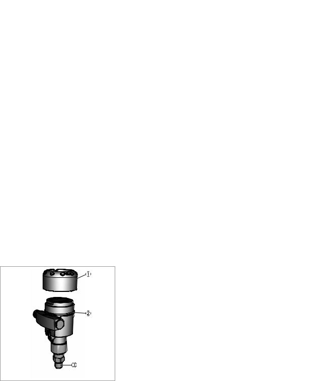
2.2.1 Device design
The following drawing shows the basic components of the pressure transmitter.
Figure 2-2: Basic components of single chamber pressure transmitter
1Housing cover, optional with display and adjustment module below
2Housing with electronics
3Process assembly with measuring cell
12 |
www.krohne.com |
04/2014 - 4003437201 - MA OPTIBAR PC 5060 C R01 en |

|
|
DEVICE DESCRIPTION 2 |
|
OPTIBAR PC 5060 C |
|
|
|
|
Figure 2-3: Basic components of double chamber pressure transmitter
1Housing cover
2Housing with electronics
3Process assembly with measuring cell
4Housing cover, optional with display and adjustment module below
5Operating and display module
2.3Nameplates
INFORMATION!
Look at the device nameplate to ensure that the device is delivered according to your order. Check for the correct supply voltage printed on the nameplate.
Figure 2-4: Example for nameplate for a OPTIBAR * 5060
1Observe the installation and operating instructions
2CE marking and marking of notified body
3Hardware and Software version
4Product name and type code
5Nominal range
Permissible process pressure
6Permissible temperature range
7Electronics power supply and signal output
8Ingress protection and material of wetted parts (Diaphragm, process connections, gasket and fill fluid)
9Approvals and approval guidelines
04/2014 - 4003437201 - MA OPTIBAR PC 5060 C R01 en |
www.krohne.com |
13 |

2 DEVICE DESCRIPTION |
|
|
OPTIBAR PC 5060 C |
|
|
|
|
|
2.4 Terms and abbreviations
The following terms and abbreviations are used in this document.
|
|
DEVICE DESCRIPTION 2 |
|
OPTIBAR PC 5060 C |
|
|
|
|
2.5 Sealing concept
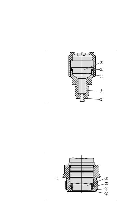
2.5.1 Sealing concept for recessed installation
Figure 2-5: Recessed installation of the CERTEC® measuring cell
1Measuring cell
2Measuring cell seal
3Process diaphragm
4Process connection
5Seal for the process connection (optional)
2.5.2Sealing concept for flush mounted installation with single seal
Figure 2-6: Flush mounted installation of the CERTEC® measuring cell
1Measuring cell
2Measuring cell seal
3Process diaphragm
4Process connection
5Seal for the process connection (optional)
04/2014 - 4003437201 - MA OPTIBAR PC 5060 C R01 en |
www.krohne.com |
15 |
2 DEVICE DESCRIPTION |
|
|
|
|
|
|
|
OPTIBAR PC 5060 C |
|
||
2.5.3 Sealing concept for flush mounted installation with double seal |
|
|
|||
|
|
||||
|
|
|
|
|
|
|
|
|
|
|
|
Figure 2-7: Flush mounted installation of the CERTEC® measuring cell with double seal
1Measuring cell
2Measuring cell seal
3Process diaphragm
4Process connection
5Additional front measuring cell seal
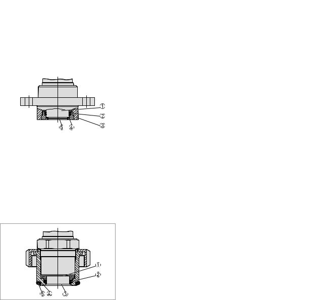
2.5.4Sealing concept for hygienic installation
Figure 2-8: Hygienic installation of the CERTEC® measuring cell
1Measuring cell
2Measuring cell moulded seal
3Process diaphragm
4Process connection
5Gap-free seal for process connection
16 |
www.krohne.com |
04/2014 - 4003437201 - MA OPTIBAR PC 5060 C R01 en |

|
|
INSTALLATION 3 |
|
OPTIBAR PC 5060 C |
|
|
|
|
3.1 General notes on installation
INFORMATION!
Inspect the packaging carefully for damages or signs of rough handling. Report damage to the carrier and to the local office of the manufacturer.
INFORMATION!
Do a check of the packing list to make sure that you have all the elements given in the order.
INFORMATION!
Look at the device nameplate to ensure that the device is delivered according to your order. Check for the correct supply voltage printed on the nameplate.
3.2 Protection category of the housing
The housing of the differential pressure transmitter fulfills the requirements for ingress protection in accordance with IEC 60529. Housing for protection category IP69K in accordance with ISO 20653 is also available. For further information refer to Technical data on page 59.
CAUTION!
The first digit stands for the protection of the inner electronic components against the ingress of foreign bodies including dust. The first digit "6" means that the housing is dust-proof. The second digit designates the protection of the inner electronic components against the ingress of water. The second digit "6" means that the housing is waterproof and also resistant against a strong jet of water resists. The number "7" means that the case is waterproof even under water for a given pressure and time. The number "8" means that the housing is permanently waterproof even under water.
3.3 Packaging
CAUTION!
Devices for oxygen applications are sealed in PE foil and provided with a label "Oxygen! Use no Oil". Remove this foil just before mounting the device! After removing the protection for the process connection the label O2 will be visible on the process connection. Penetration of oil,
grease and dirt should be avoided. Danger of explosion!
Your device was protected by packaging during transport. Its capacity to handle normal loads during transport is assured by a test following ISO 22248. The packaging of standard devices consists of environmentally friendly, recyclable cardboard and PE foil. For special versions, PE foam or PE foil is also used. Dispose of the packaging material via specialised recycling companies.
04/2014 - 4003437201 - MA OPTIBAR PC 5060 C R01 en |
www.krohne.com |
17 |

3 INSTALLATION |
|
|
OPTIBAR PC 5060 C |
|
|
|
|
|
3.4 Storage
CAUTION!
Observe the storage information found on the packaging. Labels on the original packaging must always remain legible and may not be damaged.
•Store the device in a dry and dust-free location.
•Avoid lasting direct exposure to the sun.
•Store the device in the original packaging supplied.
•Do not expose to aggressive media.
•Avoid mechanical shocks.
•Storage temperature of -40 to +80°C / -40 to +176°F.
•Relative air humidity of 20 to 85%.
3.5Transport
•Use original packaging for transport and ensure that the packaging does not get crushed or damaged by sharp objects or other boxes.
•Do not throw or drop the device.
•Avoid temperatures below -40°C / -40°F and above +80°C / +176°F.
•When transporting by ship, use seaworthy outer packing.
3.6Installation specifications
INFORMATION!
Observe the relevant directives, ordinances, standards and accident prevention regulations (e.g. VDE/VDI 3512, DIN 19210, VBG, Elex V, etc.).
Ensure that all of the parts in the process are suitable for the current process conditions. This includes in particular:
•Parts active in the measurement
•Process connection
•Process seal
Process conditions include in particular:
•Process pressure
•Process temperature
•Chemical properties of the media
•Abrasion and mechanical impact
18 |
www.krohne.com |
04/2014 - 4003437201 - MA OPTIBAR PC 5060 C R01 en |
|
|
INSTALLATION 3 |
|
OPTIBAR PC 5060 C |
|
|
|
|
3.7 Mounting
CAUTION!
•Prior to installing the pressure transmitter, it is essential to verify whether the version of the device on hand completely fulfils the technical and safety requirements of the measuring point. This applies in particular to the measuring range, overpressure resistance, temperature, explosion protection and operating voltage.
•Check the materials used for the wetted parts (e.g. gasket, process connection, separating diaphragm etc.) for suitability as regards process compatibility.
3.7.1Rotating the housing
The transmitter housing can be rotated 350° for better readability of the display or access to the wiring. A stop prevents the housing from being rotated too far.
• On all 2 chamber housings, the locking screw must first be loosened at the neck of the housing.
i The housing can then be rotated to the desired position.
•Once the desired position is reached, the locking screw is tightened again.
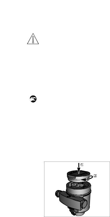
3.7.2Mounting the display and adjustment module
The optional display and adjustment module can be set in any one of four different positions at 90° intervals. The installation of the adjustment module is carried out as per the illustrations below. To do so, unscrew the housing cover and insert the adjustment module clockwise. The display can be installed rotated at 90°. It is not necessary to interrupt the power supply.
Figure 3-1: Installation in single chamber housing
1Insert the display and adjustment module into the housing
2Turn the display and adjustment module clockwise
04/2014 - 4003437201 - MA OPTIBAR PC 5060 C R01 en |
www.krohne.com |
19 |
3 INSTALLATION |
|
|
|
|
|
|
|
OPTIBAR PC 5060 C |
|
||
|
|
|
|
|
|
|
|
|
|
|
|
|
|
|
|
|
|
|
|
|
|
|
|
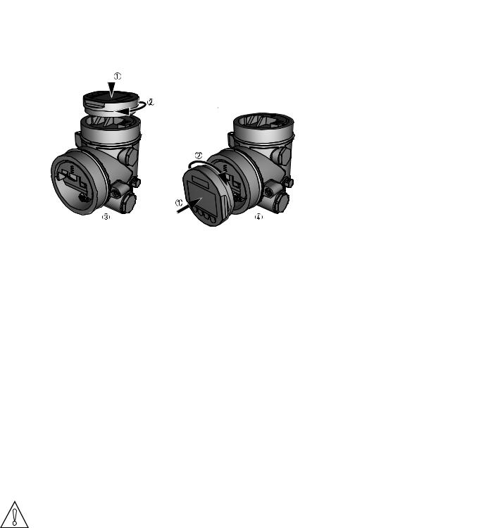
Figure 3-2: Installation in double chamber housing
1Insert the display and adjustment module into the housing
2Turn the display and adjustment module clockwise
3Mounting on top
4Mounting at side
3.7.3Temperature limits
Higher process temperatures often mean also higher ambient temperatures for electronics and connection cables. Make sure that the upper temperature limits for the environment of the electronics housing and connection cable are not exceeded. For further information refer to
Technical data on page 59.
3.8 Instructions for oxygen applications
Oxygen and other gases can be explosive when brought into contact with oils, grease and plastics, so the following measures must also be taken:
•All components of the plant, such as e.g. measuring devices must be cleaned according to the requirements of BAM (DIN 19247).
•Depending on the seal material, certain temperatures and pressures must not be exceeded in oxygen applications, refer to Technical data on page 59.
CAUTION!
Devices for oxygen applications are sealed in PE foil and provided with a label "Oxygen! Use no Oil". Remove this foil just before mounting the device! After removing the protection for the process connection the label O2 will be visible on the process connection. Penetration of oil,
grease and dirt should be avoided. Danger of explosion!
20 |
www.krohne.com |
04/2014 - 4003437201 - MA OPTIBAR PC 5060 C R01 en |
|
|
INSTALLATION 3 |
|
OPTIBAR PC 5060 C |
|
|
|
|
3.9 Venting
CAUTION!
The filter element causes a delayed pressure equalisation when the housing cover is opened or closed quickly. During the process the measurement can change by up to 15 mbar for up to 5 seconds.
CAUTION!
In order to ensure effective ventilation, the filter element must be always free of deposits.
CAUTION!
Do not use a high-pressure cleaner to clean the housing. The filter element may become damaged and as a result moisture can penetrate into the housing. The exception to this is the IP69K single chamber housing.
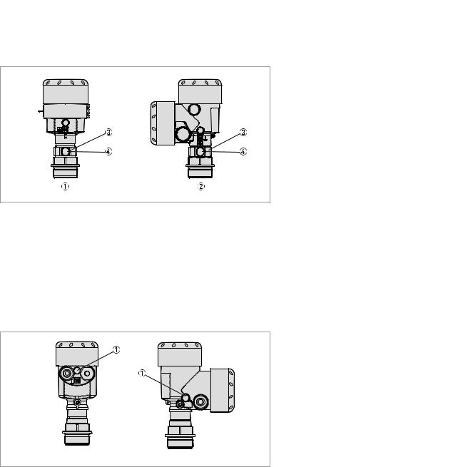
The ventilation for the electronics housing is assured via a filter element in the vicinity of the cable glands, which is permeable to air but water-absorbent.
Figure 3-3: Venting in non-Ex, Ex ia and Ex d ia versions
1Single chamber housing, plastic, stainless steel precision casting
2Single chamber housing, aluminium
3Single chamber housing, electro-polished stainless steel
4Double chamber housing, plastic
5Double chamber housing, aluminium
6Filter element
The following devices feature a dummy plug instead of a filter element:
•Devices in the IP 66 / IP 68 (1bar) protection category - venting via capillary tube in permanently connected cable
•Devices with absolute pressure
04/2014 - 4003437201 - MA OPTIBAR PC 5060 C R01 en |
www.krohne.com |
21 |
3 INSTALLATION |
|
|
OPTIBAR PC 5060 C |
|
|
|
|
|
Devices in Ex d version
Figure 3-4: Ventilation Ex-housing
1Single chamber housing, aluminium and stainless steel precision casting
2Double chamber housing, aluminium and stainless steel precision casting
3Rotating metal ring
4Filter element
The filter element is integrated into the sensor assembly via a rotating metal ring. Align the metal ring towards the bottom to better protect the filter element from deposits. Devices with absolute pressure feature a dummy plug instead of a filter element.
Devices with second process barrier
Figure 3-5: Ventilation gas-proof feedthrough
1 Filter element
For devices with a second process barrier, the sensor assembly is completely encased by an additional, gas-proof feedthrough. Additional venting is not required for absolute pressure sensors. With relative pressure sensors, the ambient pressure is measured and compensated by an additional sensor in the electronics.
22 |
www.krohne.com |
04/2014 - 4003437201 - MA OPTIBAR PC 5060 C R01 en |
|
|
INSTALLATION 3 |
|
OPTIBAR PC 5060 C |
|
|
|
|
Devices in IP69K version
Figure 3-6: Ventilation IP69K
Filter element
Devices with absolute pressure feature a dummy plug instead of a filter element.
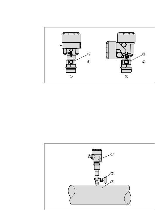
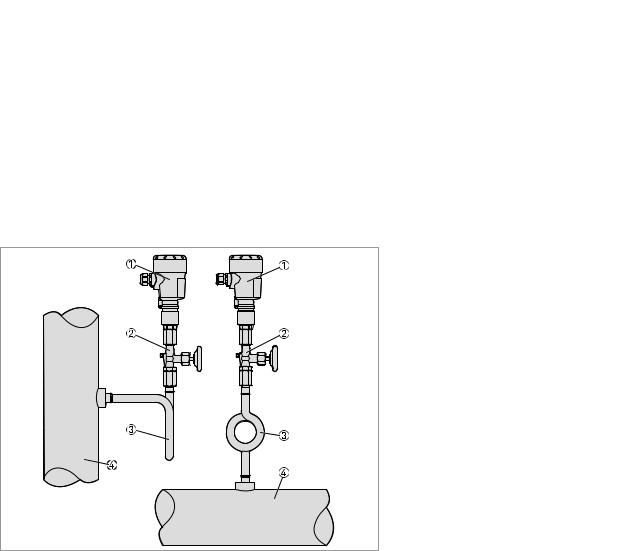
3.10 Measurement setup for process pressure measurement
The following points should be observed in this application:
• The signal converter must be mounted above the measuring point.
Figure 3-7: Measurement setup for measuring the process pressure of gases
1Pressure transmitter
2Shut-off valve
3Tapping point
04/2014 - 4003437201 - MA OPTIBAR PC 5060 C R01 en |
www.krohne.com |
23 |
3 INSTALLATION |
|
|
OPTIBAR PC 5060 C |
|
|
|
|
|
3.11 Measurement setup for steam measurement
The following points should be observed in this application:
•The pressure transmitter should be connected via a siphon to protect the measuring cell from non-permitted high temperatures.
•Siphon to be kept free of insulation.
•When using superheated steam, the siphon must be filled with water prior to start-up.
Figure 3-8: Measurement setup for steam measurement
1Pressure transmitter
2Shut-off valve
3Siphon
4Tapping point
24 |
www.krohne.com |
04/2014 - 4003437201 - MA OPTIBAR PC 5060 C R01 en |
|
|
INSTALLATION 3 |
|
OPTIBAR PC 5060 C |
|
|
|
|
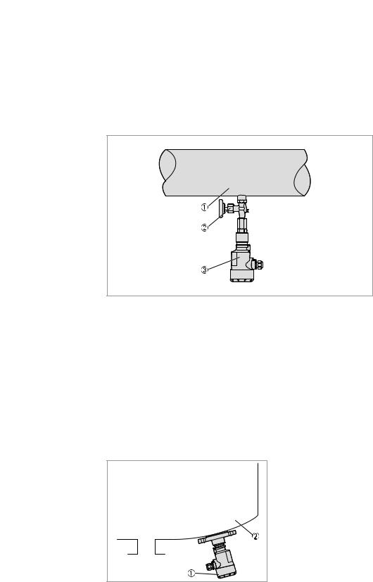
3.12 Measurement setup for liquid measurement
The following points should be observed in this application:
• The signal converter must be mounted below the measuring point.
Figure 3-9: Measurement setup for liquid measurement
1Tapping point
2Shut-off valve
3Pressure transmitter
3.13Measurement setup for level measurement
The following points should be observed in this application:
•The pressure transmitter should be mounted below the lowest level.
•The pressure transmitter should be protected from filling/emptying current and agitator surges when mounted.
Figure 3-10: Measurement setup for level measurement
1Pressure transmitter
2Tank
04/2014 - 4003437201 - MA OPTIBAR PC 5060 C R01 en |
www.krohne.com |
25 |
3 INSTALLATION |
|
|
OPTIBAR PC 5060 C |
|
|
|
|
|
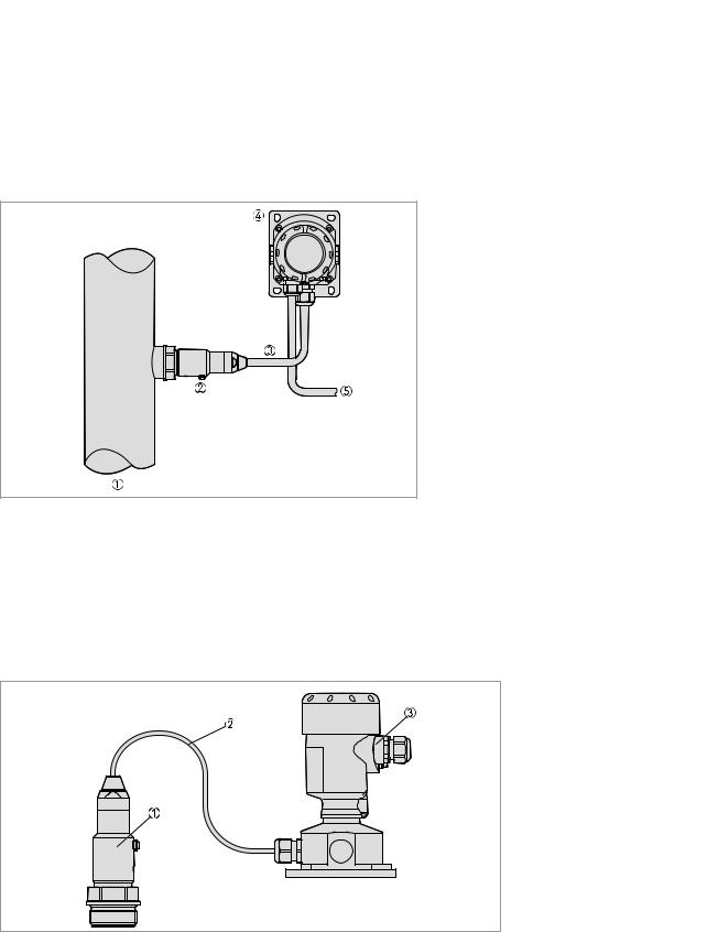
3.14 External housing
A mounting plate is available as an option to facilitate the mounting of the external housing. For further information refer to Technical data on page 59.
Figure 3-11: Measurement setup with an external housing
1Tapping point
2Sensor assembly
3Connecting cable
4External housing
5Signal cable
IP 68 version (25 bar)
Figure 3-12: Process assembly
1Sensor assembly
2Connection cable
3External housing
26 |
www.krohne.com |
04/2014 - 4003437201 - MA OPTIBAR PC 5060 C R01 en |
|
|
|
|
INSTALLATION 3 |
|
OPTIBAR PC 5060 C |
|||
|
|
|
|
|
|
|
|
|
|
|
|
|
|
|
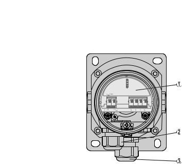
Figure 3-13: External housing (IP 68)
Electronic insert
Cable gland for the power supply
Cable gland for the sensor connection cable
04/2014 - 4003437201 - MA OPTIBAR PC 5060 C R01 en |
www.krohne.com |
27 |

4 ELECTRICAL CONNECTIONS |
|
|
OPTIBAR PC 5060 C |
|
|
|
|
|
4.1 Safety instructions
DANGER!
All work on the electrical connections may only be carried out with the power disconnected. Take note of the voltage data on the nameplate!
DANGER!
Observe the national regulations for electrical installations!
WARNING!
Observe without fail the local occupational health and safety regulations. Any work done on the electrical components of the measuring device may only be carried out by properly trained specialists.
INFORMATION!
Look at the device nameplate to ensure that the device is delivered according to your order. Check for the correct supply voltage printed on the nameplate.
4.2 Notes for electrical cables
DANGER!
The device must be grounded to a spot in accordance with regulations in order to protect personnel against electric shocks.
DANGER!
Cables may only be connected when the power is switched off! Since the transmitter has no switch-off elements, overcurrent protection devices, lightning protection and/or energy isolating devices must be provided by the customer.
28 |
www.krohne.com |
04/2014 - 4003437201 - MA OPTIBAR PC 5060 C R01 en |
 Loading...