


MFC-400
Supplementary instructions
Supplementary instructions
MFC 400
MFC 400
MFC 400MFC 400
Supplementary instructions Supplementary instructions
Signal converter for mass flowmeters
Description of PROFIBUS interface
Description of PROFIBUS interface
Description of PROFIBUS interfaceDescription of PROFIBUS interface
PROFIBUS PA:
PROFIBUS PA:
PROFIBUS PA:PROFIBUS PA:
PROFIBUS device with MBP Physical Interface and PA Profile 3.02 (V1.0.3_ / 130603)
PROFIBUS DP:
PROFIBUS DP:
PROFIBUS DP:PROFIBUS DP:
PROFIBUS device with RS485 Physical Interface and PA Profile 3.02 (V1.0.3_ / 130603)
The documentation is only complete when used in combination with the relevant
documentation for the .
© KROHNE 06/2013 - 4002835301 - AD MFC 400 PROFIBUS R01 en

CONTENTS
MFC 400
1 Safety instructions 4
1.1 Scope of the document..................................................................................................... 4
1.2 Scope of delivery............................................................................................................... 4
1.3 Special notes .................................................................................................................... 4
2 PROFIBUS DP 5
2.1 Software history ............................................................................................................... 5
2.2 System configuration of PROFIBUS DP network............................................................. 5
2.3 Electrical connection for DP signal converter................................................................. 6
2.4 Technical data................................................................................................................... 8
2.5 PROFIBUS PA Profile implementation ............................................................................ 9
2.6 GSD files ........................................................................................................................... 9
2.7 Ident. Number selector .................................................................................................. 10
2.8 Summary ........................................................................................................................ 13
2.9 Baud rate ........................................................................................................................ 14
3 PROFIBUS PA 15
3.1 Software history ............................................................................................................. 15
3.2 System configuration of PROFIBUS PA network ........................................................... 16
3.3 Electrical connection for PA signal converter ............................................................... 17
3.4 Technical data................................................................................................................. 18
3.5 PROFIBUS PA Profile implementation .......................................................................... 19
3.6 GSD files ......................................................................................................................... 19
3.7 Ident. Number selector .................................................................................................. 20
3.8 Summary ........................................................................................................................ 23
4 Commissioning / Operation 24
4.1 Configuration of cyclic data transfer.............................................................................. 24
4.2 Cyclic data....................................................................................................................... 24
4.2.1 Input data .............................................................................................................................. 24
4.2.2 Output data............................................................................................................................ 30
4.3 Diagnosis ........................................................................................................................ 31
4.3.1 Mapping of DIAGNOSIS_EXTENSION bits into DIAGNOSIS bits if "Condensed Status and Di-
agnosis" handling selected ............................................................................................................ 37
4.3.2 Mapping of DIAGNOSIS_EXTENSION bits into DIAGNOSIS bits if "Classic Status and Diagno-
sis" handling selected .................................................................................................................... 40
4.3.3 Variable "Event groups"........................................................................................................ 42
4.3.4 Filtering of "Single events"................................................................................................... 45
2
www.krohne.com 06/2013 - 4002835301 - AD MFC 400 PROFIBUS R01 en

MFC 400
CONTENTS
5 Profibus settings 46
5.1 Menu A, Quick Setup ...................................................................................................... 46
5.2 Menu B, Test................................................................................................................... 46
5.3 Menu C, Setup................................................................................................................. 47
5.4 Menu D, Service.............................................................................................................. 51
5.5 Status messages and diagnostic information................................................................ 52
6 Notes 54
www.krohne.com06/2013 - 4002835301 - AD MFC 400 PROFIBUS R01 en
3

1 SAFETY INSTRUCTIONS
1.1 Scope of the document
These instructions are supplementary to the signal converter Handbook. For all other data, use
the relevant chapters of the Handbook. If you do not have this document, please contact the
nearest office or download them from the manufacturer's internet site.
INFORMATION!
The information in this chapter only contains the data applicable to PROFIBUS communication.
The technical data in the Handbook shall be valid in its current version, provided that it is not
rendered invalid or replaced by this supplement.
1.2 Scope of delivery
The information in this chapter only contains the data applicable to PROFIBUS communication.
The technical data in the Handbook shall be valid in its current version, provided that it is not
rendered invalid or replaced by this supplement.
A device for PROFIBUS communication is supplied with:
MFC 400
• Supplementary instructions for PROFIBUS communication
• PROFIBUS device data files (GSD) which can be also downloaded from the manufacturer's
internet site
1.3 Special notes
Don't switch off (power off) the signal converter immediately after manual change of parameter
values:
• Please wait approx. 10 seconds before you switch off the signal converter after you have done
both a parameter download via PROFIBUS or a manual change of a parameter value via the
local display.
CAUTION!
Please wait approx. 15 seconds before you switch off the signal converter after you have carried
out a "Factory Reset" (PROFIBUS "Coldstart") via PROFIBUS or local display.
"Deactivation of the Service Parameter Lock" of the signal converter via PROFIBUS:
• After writing down the service password (via PROFIBUS) the "Deactivation of the Service
Parameter Lock" will last at least 20 minutes if the internal password timer of the signal
converter won't be retriggered by writing this password again. The "Deactivation of the
Service Parameter Lock" will be terminated at once by a PROFIBUS Coldstart / Warmstart or
if the internal password timer of the signal converter elapsed.
4
www.krohne.com 06/2013 - 4002835301 - AD MFC 400 PROFIBUS R01 en

MFC 400
2.1 Software history
Issued Signal converter Application program System integration
PROFIBUS DP 2
Mth./
Hardware Firmware Hardware Software Driver Version Model name
year
06/13 Signal
converter
with
RS485
interface +
PA Profile
3.02
V1.0.3_ /
130603
Simatic
PCS7
other SPS
of other
manufact.
Laptop / PC PDM
HW Config
other
Software of
other SPS
manufact.
(≥ 6.0 SP5)DD(Ident.-No.)
Pactware DTM ≥ - -
GSD
manuf.
specific
GSD
profile
specific
The PROFIBUS DP device has a RS485 interface to connect the device to a PROFIBUS DP
network.
The software supports the PROFIBUS PA Profile 3.02. Both, cyclic services towards a control
system (e.g. PLC) as well as acyclic services for operating with engineering tools (e.g. DD/DTM
based tools) are supported.
The PROFIBUS station address can be set via PROFIBUS services or via the device display.
2.2 System configuration of PROFIBUS DP network
KR014512.GSD MFC400
(RS485)
Rev.1
PA039742.GSD Flow, dens,
temp with
3AI, 1TOT
(PhyL 0)
- -
The following diagram shows a typical network configuration with PROFIBUS devices with RS485
interface in a non-hazardous environment. The PROFIBUS devices with RS485 interface do not
need any segment coupler. They are connected directly to the PROFIBUS DP network.
Figure 2-1: PROFIBUS DP network
1 SPS
2 PROFIBUS DP with max. 12 Mbit/s
3 Signal converter
4 Other devices with PROFIBUS RS485 interface
www.krohne.com06/2013 - 4002835301 - AD MFC 400 PROFIBUS R01 en
5
2 PROFIBUS DP
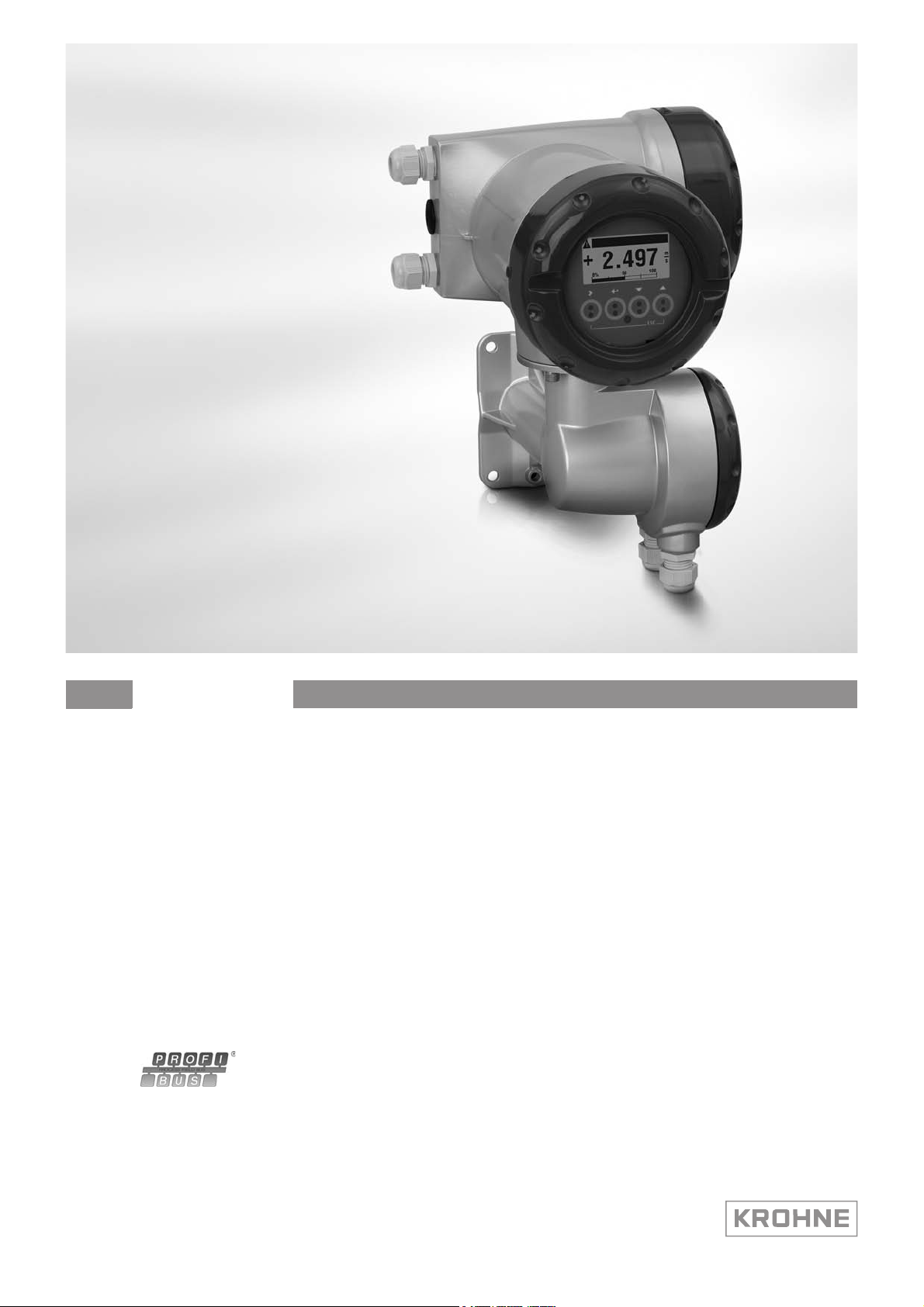
2.3 Electrical connection for DP signal converter
INFORMATION!
For a detailed description of the electrical connections please refer to the standard signal
converter handbook.
Signal converter terminals B B- C C- D D-
PROFIBUS designation T +B -A -T +B -A
1 2 3 4 5 6
1 Termination positive
2 TxD+/RxD+ second connection
3 TxD-/RxD- second connection
4 Termination negative
5 TxD+/RxD+ first connection
6 TxD-/RxD- first connection
MFC 400
External connection with spur
CAUTION!
Spurs are not allowed at high data rates!
I = 110 nH
R1 = 390 Ω
R2 = 220 Ω
6
www.krohne.com 06/2013 - 4002835301 - AD MFC 400 PROFIBUS R01 en
MFC 400
PROFIBUS DP 2
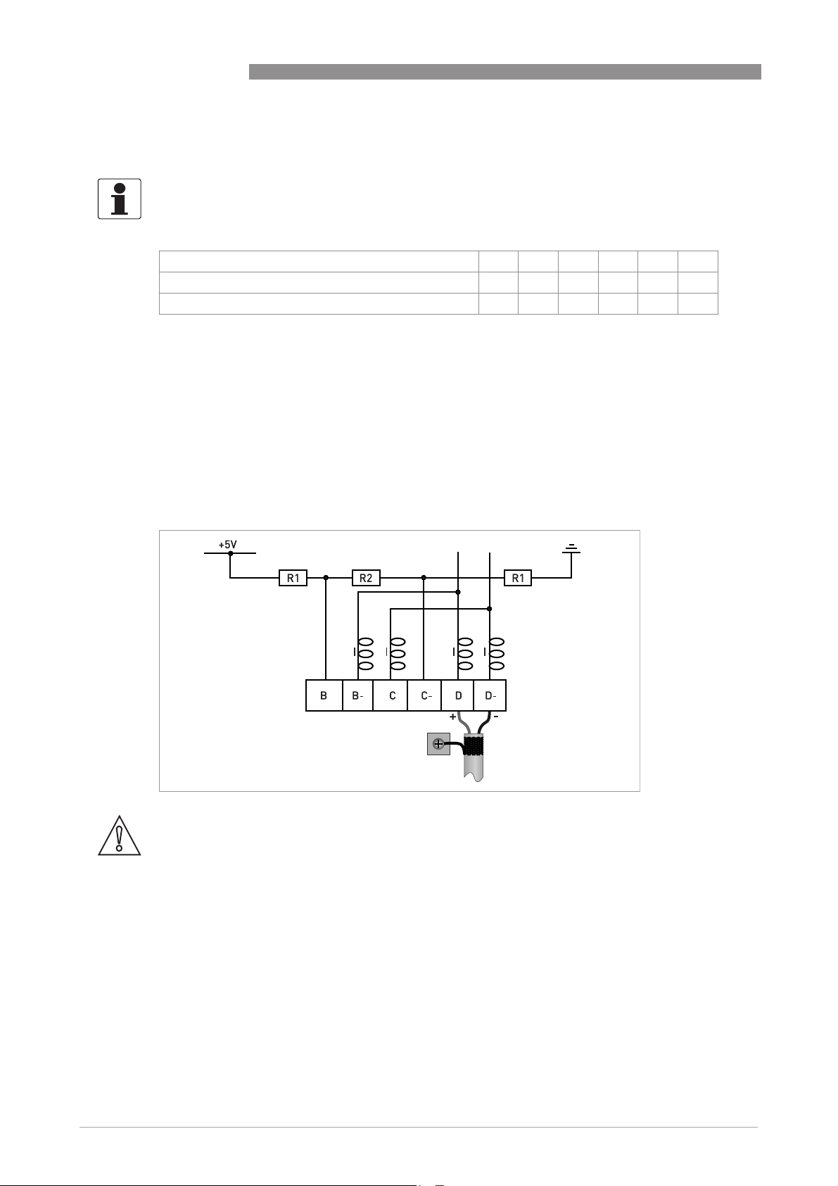
External connection at last device with active internal bus termination
I = 110 nH
R1 = 390 Ω
R2 = 220 Ω
External connection to a trunk
1 e.g. incoming data lines
2 e.g. outgoing data lines
I = 110 nH
R1 = 390 Ω
R2 = 220 Ω
www.krohne.com06/2013 - 4002835301 - AD MFC 400 PROFIBUS R01 en
7

2 PROFIBUS DP
2.4 Technical data
Hardware
Type PROFIBUS RS485 interface according to IEC 61158-2
Connection Dependent of polarity; please note at electrical connection!
Software
GSD GSD file on CD-ROM or from internet site
Device profile PROFIBUS PA Profile 3.02; conformance class B, compact
Address range 0…126 (default 126)
Local control Local display and operator interface at device
SAPs 2 x MS1 SAPs – acyclic interface to PLC
Function blocks 1 x TB = Transducer Block: contains the parameters and functions
MFC 400
Supported GSD:
• KRO14512.GSD
• PA039742.GSD
0…125 via PROFIBUS service set_slave_add
0…126 via local display
126 via factory_reset = 2712
3 x MS2 SAPs – the number of MS2 Service Access Points is typically
equal to the maximum number of master class 2 tools
defined in PA Profile 3.02
1 x PB = Physical Block: contains the parameters defined in PA
Profile 3.02
8 x AI = Analog Input Blocks: contains the parameters defined in PA
Profile 3.02
3 x TOT = Totalizer Function Blocks: contains the parameters defined
in PA Profile 3.02
8
www.krohne.com 06/2013 - 4002835301 - AD MFC 400 PROFIBUS R01 en

MFC 400
2.5 PROFIBUS PA Profile implementation
The PROFIBUS PA Profile 3.02 defines standardized parameters and functions for PROFIBUS
devices used for process control. It describes a PROFIBUS device as a function block application,
i.e. parameters and functions are grouped into different blocks. In the MFC 400 PROFIBUS
device the following blocks are implemented:
Block Usage
1 Physical Block (PB) contains identification and diagnosis parameters of the device
1 Flow Transducer Block
(TB)
8 Analog Input Function Block
(AI-FB)
3 Totalizer Function Blocks
(TOT-FB)
The Analog Input Function Block and the Totalizer Function Blocks provide the data interface
towards a process control system (e.g. a PLC); i.e. their input/output data can be read/written by
the control system. In a PROFIBUS network this is done via cyclic communication services.
contains parameters and functions to control the flow measurement
contains parameters and functions to control the measuring output;
provides the measuring value(s)
contains parameters and functions to control/provide the counter
value(s)
PROFIBUS DP 2
From the PROFIBUS point of view the MFC 400 device is designed as a compact device with 11
slots. While the Analog Input function blocks are assigned to slot 1, 2, 3, 7, 8, 9, 10 and 11 the
Totalizer Function Blocks are assigned to slot 4, 5 and 6. This assignment is fixed and cannot be
modified by the user. Nevertheless during network configuration the user can choose which
function block data shall be transferred between the PROFIBUS master and the PROFIBUS
device.
2.6 GSD files
The GSD file contains information that will be needed for configuration of the PROFIBUS DP
communication network. Supplementary files (e.g. ___.bmp and ___.dib) contain icons which will
represent the PROFIBUS devices in the view of the bus configuration system/master system. The
files must be loaded into the configuration program before. Follow the instructions in the
manual of the host supplier when installing GSD file and supplementary files.
A PROFIBUS GSD ZIP file (e.g. GSD-4002171502.zip) including both all GSD files of all KROHNE
devices with PROFIBUS PA interface and all additional data files mentioned above are available
at the KROHNE download page (e.g. http://www.krohne.com/html/dlc/GSD-4002171502.zip).
INFORMATION!
If it is supported by the host configuration tool the device entry for the MFC400 PROFIBUS device
will be located within the slave family "PROFIBUS PA".
www.krohne.com06/2013 - 4002835301 - AD MFC 400 PROFIBUS R01 en
9

2 PROFIBUS DP
2.7 Ident. Number selector
Within a PROFIBUS network the type of a PROFIBUS slave is identified by its Ident. Number
which is unique for this slave type. The PROFIBUS DP device supports two different Ident.
Numbers. Therefore it can be installed for different use cases. When the Ident. Number is
changed the behaviour of the device concerning the cyclic data transfer is changed; i.e. the
maximum number of transferred measuring values and/or the length and content of the
diagnosis information will be different. The user can select the required Ident. Number by an
engineering tool (e.g. DD/DTM - parameter IDENT_NUMBER_SELECTOR slot 0; index 40) or via
the MFC 400 device display menu (menu item "Identification No.", C6.8.7).
The following settings are supported:
• Automatic adaptation mode (factory setting)
• Manufacturer specific Ident. Number (4512 hex)
• Profile specific Ident. Number (9742 hex)
Automatic adaptation mode (factory setting)
If the parameter IDENT_NUMBER_SELECTOR is set to this mode the device will select its
operation mode during start-up of the cyclic data transfer according to the used GSD file. The
active Ident. Number is set to one of the settings described below. If the
IDENT_NUMBER_SELECTOR is changed to this mode the current Ident. Number is not changed
until the cyclic data transfer is (re-)started.
MFC 400
INFORMATION!
Depending on the components in the PROFIBUS network the automatic adaptation might fail. In
this case the active Ident. Number has to be selected by the user via an engineering tool or via
the device display menu. The parameter IDENT_NUMBER_SELECTOR has to be set to a fixed
Ident. Number.
10
www.krohne.com 06/2013 - 4002835301 - AD MFC 400 PROFIBUS R01 en

MFC 400
PROFIBUS DP 2
Manufacturer specific Ident. Number (4512 hex)
This setting provides complete functionality of the PROFIBUS DP device. All function Blocks are
available for cyclic data transfer. Device specific diagnosis information is transferred in addition
to the Profile diagnosis.
Cyclic layout:
Slot Description Function Block types Default unit
1 Mass Flow AI-FB kg/s
2 Density AI-FB kg/l
3 Temperature AI-FB K
4 Mass Totaliser Totaliser-FB kg
5 Volume Totaliser Totaliser-FB
6 Mass Totaliser Totaliser-FB kg
7 Volume Flow AI-FB
8 Concentration 1 AI-FB %
9 Concentration 2 AI-FB %
10 Concentration Mass Flow 1 AI-FB kg/s
11 Concentration Mass Flow 2 AI-FB kg/s
3
m
m3/h
• AI: Analog Input Function Block
• FB: Function Block
There are separate settings to select the units for local display and PROFIBUS. Modifications of
the units of the display will have no effect on the data transferred via PROFIBUS.
A master class 2 tool is required to modify the units for PROFIBUS transfer.
Valid GSD Modules:
AI-FB Empty Module
Totaliser-FB Empty Module
AI: Out
TOT (Id.F.): Total
TOT (Id.F.): SetTot + Total
TOT (Id.F.): ModeTot + Total
TOT (Id.F.): SetTot+ModeTot+Total
TOT (Id.F.): SetTot
TOT (Id.F.): ModeTot
TOT (Id.F.): SetTot + ModeTot
GSD File required:
GSD file KRO14512.GSD
the PROFIBUS DP device. All function blocks are available for cyclic data transfer.
KRO14512.GSD is required in this mode. This GSD file provides complete functionality of
KRO14512.GSDKRO14512.GSD
INFORMATION!
If another GSD file is used in the PROFIBUS master system the cyclic data transfer cannot be
established in this setting.
www.krohne.com06/2013 - 4002835301 - AD MFC 400 PROFIBUS R01 en
11

2 PROFIBUS DP
INFORMATION!
During network configuration the user has to define which function block outputs of the signal
converter should be transferred cyclically to the master. This is performed by a bus
configuration tool (e.g. "HW- Config" for PC-S7 from Siemens). This tool offers specific functions
as follows:
1. It is possible to configure an "Empty" block (the code of an "Empty" block is defined as 0x00) on
each block number. This implies: no data are transmitted in the cyclic data telegram for this
block.
2. There is NO "Totaliser (TOT)" function block allowed on block position 1, 2, 3, 7, 8, 9, 10 and 11!
On these positions, only an "Analog Input (AI)" function block or an "Empty" block is allowed!
(Note: All codes supported by "Analog Input (AI)" - and "Totaliser (TOT)"
be found in the corresponding GSD files.)
3. There is NO "Analog Input (AI)" function block allowed on block position 4, 5 and 6! On these
positions, only a "Totaliser (TOT)" function block or an "Empty" block is allowed!
4. There is a choice of 7 different totaliser functions, which can be allocated to the blocks 4, 5
and/or 6.
MFC 400
–
function blocks will
12
www.krohne.com 06/2013 - 4002835301 - AD MFC 400 PROFIBUS R01 en

MFC 400
PROFIBUS DP 2
Profile specific Ident. Number (9742 hex)
Functionality is reduced to the requirements which are mandatory in the PA Profile; e.g. 3 x AIFB and 1 x TOT-FB are available for cyclic data transfer only. Device specific diagnosis
information is not available via cyclic PROFIBUS services. Nevertheless this behaviour will
improve interchangeability between devices of different vendors because only functions are
available which are provided by all PROFIBUS PA variable area flowmeters. Exchange is possible
without modifying the configuration of the control system.
Cyclic layout:
Slot Description Function Block type Default unit
1 Mass Flow AI-FB kg/s
2 Density AI-FB kg/l
3 Temperature AI-FB K
4 Mass Totaliser Totaliser-FB kg
Valid GSD Modules:
AI-FB EMPTY_MODULE
AI
Totaliser-FB EMPTY_MODULE
TOTAL
SETTOT_TOTAL
SETTOT_MODETOT_TOTAL
GSD File required:
GSD file PA039742.GSD
Take care that "Condensed Status and Diagnosis" is not supported by this file.
INFORMATION!
If another GSD file is used in the PROFIBUS master system the cyclic data transfer cannot be
established in this setting.
2.8 Summary
The following table shows a summary of the supported combinations of the PROFIBUS
device with RS485 Physical Interface and PA Profile 3.02:
Ident. Number Selector Ident.
Automatic adaptation mode 4512 KR014512.GSD Classic / Condensed
Manufacturer specific Ident.
Number
Profile specific Ident. Number 9742 PA039742.GSD 1 Classic
1 This file is p rovided by P ROFIBUS Interna tional (www .profibus.com) . Take care t hat "Condense d Status and Diagnosis"
is not supported by this file.
PA039742.GSD is required in this mode. This file is provided by PROFIBUS International.
PA039742.GSDPA039742.GSD
GSD File Status
Number
9742 PA039742.GSD 1 Classic
4512 KR014512.GSD Classic / Condensed
www.krohne.com06/2013 - 4002835301 - AD MFC 400 PROFIBUS R01 en
13

2 PROFIBUS DP
2.9 Baud rate
Supported baud rates are listed in the GSD file (see below). After power-on or PROFIBUS
timeout a baud rate search is active to detect the current transfer speed on the bus. It is not
necessary to set the baud rate manually.
If the data transmission rate is changed during operation the baud rate search will not be started
by the device. A new power-up or a manual interruption of the PROFIBUS communication is
required to activate the baud rate search in this case.
MFC 400
14
www.krohne.com 06/2013 - 4002835301 - AD MFC 400 PROFIBUS R01 en

MFC 400
3.1 Software history
Issued Signal converter Application program System integration
PROFIBUS PA 3
Mth./
Hardware Firmware Hardware Software Driver Version Model name
year
06/13 Signal
converter
with MBP
interface +
PA Profile
3.02
V1.0.3_ /
130603
Simatic
PCS7
other SPS
of other
manufact.
Laptop / PC PDM
HW Config
other
Software of
other SPS
manufact.
(≥ 6.0 SP5)DD(Ident.-No.)
Pactware DTM ≥ - -
GSD
manuf.
specific for
stand.
DP/PA
segment
coupler
GSD
profile
specific
KR014513.GSD MFC400 (MBP)
Rev.1
PA139742.GSD Flow, dens,
temp with
3AI, 1TOT
(PhyL 1)
- -
www.krohne.com06/2013 - 4002835301 - AD MFC 400 PROFIBUS R01 en
15

3 PROFIBUS PA
3.2 System configuration of PROFIBUS PA network
The following diagram shows a typical instrumentation with PROFIBUS PA devices with MBP
interface in hazardous and non-hazardous locations, including connections of conventional
devices (e.g. with 4...20 mA signals) in a PROFIBUS network.
As a rule, the PROFIBUS PA segment is connected to a segment coupler which, among other
things, carries out the conversion to the PROFIBUS DP bus line. It should be mentioned that the
segment coupler is normally set to a fixed baud rate on the DP side.
MFC 400
Figure 3-1: PROFIBUS PA network
1 Control system (PLC); class 1 master
2 Engineering or operation control tool; class 2 master
3 PROFIBUS DP network with max. 12 Mbit/s
4 PROFIBUS PA segment coupler DP / PA
5 Device with PROFIBUS PA interface, 31.25 kbit/s
6 HART
7 More devices with 4…20 mA
8 Analogue I/O module
®
device
16
www.krohne.com 06/2013 - 4002835301 - AD MFC 400 PROFIBUS R01 en
MFC 400
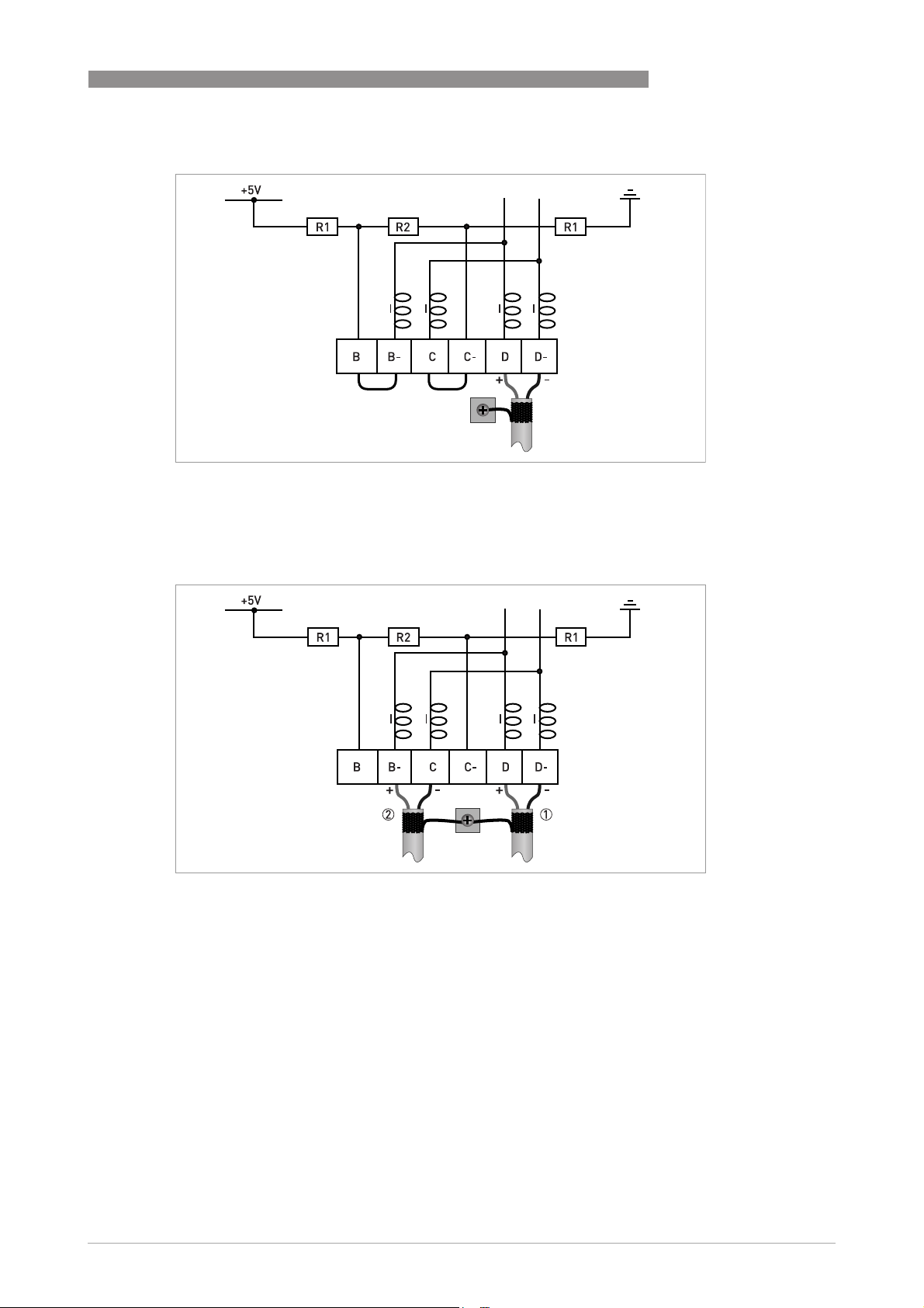
3.3 Electrical connection for PA signal converter
INFORMATION!
The wiring between the device and the PROFIBUS PA bus cable is independant of polarity.
The signal converter PROFIBUS PA interface will operate only if the additional power supply for
the device is connected/available.
For a detailed description of the electrical connections please refer to the standard signal
converter handbook. Refer also to the PROFIBUS PA user and installation guideline (Version 2.2,
February 2003 PNO order no. 2.092).
Connection to a spur
or
PROFIBUS PA 3
Connection to a trunk
1 e.g. incoming data lines
2 e.g. outgoing data lines
or
www.krohne.com06/2013 - 4002835301 - AD MFC 400 PROFIBUS R01 en
17
 Loading...