


MFC 300 |
Supplementary instructions |
|
Signal converter for mass flowmeters
Description of Modbus interface
Electronic Revision: ER 3.3.xx (SW.REV. 3.3x)
Modbus version 1.0.x
The documentation is only complete when used in combination with the relevant documentation for the sensor.
© KROHNE 11/2009 - 4000744801 - AD Modbus MFC 300 R01 en

|
CONTENTS |
|
|
|
MFC 300 |
|
|
|
|
|
|
1 |
Important information |
3 |
|
|
|
|
|
2 |
Technical data |
4 |
|
|
|
|
|
|
2.1 |
General technical data ..................................................................................................... |
4 |
|
2.2 |
Technical data of the Modbus interface (acc. to EIA standards) ..................................... |
4 |
3 |
Connection in bus systems |
5 |
|
|
|
|
|
4 |
Local configuration |
6 |
|
|
|
|
|
5 |
Electrical connection |
7 |
|
|
|
|
|
6 |
Modbus protocol |
8 |
|
|
|
|
|
|
6.1 |
General information concerning the protocol ................................................................. |
8 |
|
6.2 |
RTU frame format............................................................................................................. |
8 |
|
6.3 |
Addressing........................................................................................................................ |
9 |
|
6.4 |
Overview of supported functions...................................................................................... |
9 |
|
6.5 |
Device identification on the Modbus interface............................................................... |
10 |
|
6.6 |
Coil registers .................................................................................................................. |
10 |
6.6.1 Converter controls ................................................................................................................ |
10 |
6.6.2 Counter controls ................................................................................................................... |
11 |
6.6.3 Start calibration functions .................................................................................................... |
11 |
6.7 Input registers ................................................................................................................ |
12 |
6.8 Holding registers............................................................................................................ |
13 |
6.8.1 Counter parameters ............................................................................................................. |
13 |
6.8.2 Process input filter parameters ........................................................................................... |
14 |
6.8.3 Modbus parameters.............................................................................................................. |
16 |
6.9 Diagnostics ..................................................................................................................... |
16 |
6.10 Calibration procedures................................................................................................. |
17 |
6.10.1 Zero Calibration .................................................................................................................. |
17 |
6.10.2 Manual Density Calibration................................................................................................. |
18 |
6.10.3 Single Point Density Calibration ......................................................................................... |
19 |
6.10.4 Two Point Density Calibration............................................................................................. |
20 |
7 Notes |
21 |
|
|
2 |
www.krohne.com |
11/2009 - 4000744801 - AD Modbus MFC 300 R01 en |

|
|
IMPORTANT INFORMATION 1 |
|
MFC 300 |
|
|
|
|
The flow converter with the RS485 interface card fitted, is able to communicate with an external device (PC or other suitable computer system) using the Modbus protocol. This option allows data exchange between PC or computer and single or multiple devices.
The bus configuration consists of one external device as a master and one or more converters as slaves. For bus operation the device address (menu C6.8.1), baudrate (menu C6.8.2) and settings (menu C6.8.3, C6.8.4, C6.8.5 & C6.8.6) must be set in the converter.
All devices connected to the bus, must have different unique addresses but the same baud rate and settings.
11/2009 - 4000744801 - AD Modbus MFC 300 R01 en |
www.krohne.com |
3 |

2 TECHNICAL DATA
2.1 General technical data
MFC 300 

Interface |
RS485, galvanically isolated |
|
|
Baud rate |
1200, 2400, 4800, 9600, 19200, 38400, 57600 or 115200 |
|
|
Protocol |
Modbus RTU (available as a separate document on request) |
|
|
Maximum participants on bus |
32 per line, master included (may be extended by repeaters) |
|
|
Coding |
NRZ bit coding |
|
|
Address range |
Modbus: 1...247 |
|
|
Transmission procedure |
Half duplex, asynchronous |
|
|
Bus access |
Master / slave |
|
|
Cable |
Screened twisted pair |
|
|
Distances |
Maximum 1.2 km / 3937 ft without repeater (dependant on |
|
baud rate and cable specifications) |
|
|
2.2 Technical data of the Modbus interface (acc. to EIA standards)
Kind of signal transmission |
Differential, 2-wire topology |
|
|
Maximum number of |
32 |
transmitter/receivers |
|
|
|
Voltage range on converter input |
-7...+12 V |
|
|
Maximum voltage on converter output |
5 V |
|
|
Minimum voltage on driver output, max. |
Udiff > 1.5 V |
load |
|
Maximum input current (off state) |
-20...+20 μA |
|
|
Receiver input voltage |
-7...+12 V |
|
|
Sensitivity of the receiver |
-200...+200 mV |
|
|
Receiver input resistance |
> 12 kΩ |
|
|
Short circuit current |
< 250 mA |
|
|
Termination / polarization resistors |
120 Ω / 560 Ω |
(if activated by the jumpers X5/X6) |
|
|
|
4 |
www.krohne.com |
11/2009 - 4000744801 - AD Modbus MFC 300 R01 en |

|
|
CONNECTION IN BUS SYSTEMS 3 |
|
MFC 300 |
|
|
|
|
For proper operation of Modbus in half duplex mode in single or multi-drop communication, it is recommended that a termination resistor is applied to both ends of the data line. The simplest form of termination is line-to-line resistor across the differential input.
In RTU mode the Modus protocol requires quiet periods on the communications bus for synchronisation. It is therefore important that the Modbus is not allowed to "float", i.e. unreferenced to 0 V, as this could lead to spurious signals due to noise pick-up. It is therefore necessary to employ biasing resistors at one point on the bus network, normally the "end".
The Modbus converter has two conditions. Default is without termination and polarization. To get the active termination and polarization the settings of jumper X5 and X6 on Modbus board must be changed then. For detailed information see chapter "Electrical Connection".
11/2009 - 4000744801 - AD Modbus MFC 300 R01 en |
www.krohne.com |
5 |

4 LOCAL CONFIGURATION |
|
|
MFC 300 |
|
|
|
|
|
Converter Fct. |
Display |
Description and settings |
No. |
|
|
|
|
|
C6.8.1 |
Slave Address |
Selects the Modbus address of the device. |
|
|
Range: 1..247 (default = 1) |
|
|
|
C6.8.2 |
Baud Rate |
Selects the baud rate of the device. |
|
|
Options: |
|
|
1200 / 2400 / 3600 / 4800 / 9600 / 19200 (default) / 38400 / 57600 / 115200 |
|
|
|
C6.8.3 |
Parity |
Selects the parity. |
|
|
Options: |
|
|
Even (default) / Odd / No |
|
|
|
C6.8.4 |
Data Format |
Selects the data format. |
|
|
Options: |
|
|
Big Endian (default) / Little Endian |
|
|
|
C6.8.5 |
Transmission Delay |
Selects the delay between receiving the last byte of a request and |
|
|
sending the first byte of the response. |
|
|
Range: 0..40ms (default = 0ms) |
|
|
|
C6.8.6 |
Stop Bits |
Selects the number of stop bits. |
|
|
Options: |
|
|
1 (default) / 2 |
|
|
|
C6.8.7 |
Information |
Displays information about the device. |
|
|
|
6 |
www.krohne.com |
11/2009 - 4000744801 - AD Modbus MFC 300 R01 en |
|
|
ELECTRICAL CONNECTION 5 |
|
MFC 300 |
|
|
|
|
Terminals A and B of the converter are dependant on the options selected at order. Refer to the standard handbook of the converter for connection details.
Modbus connections
Terminals |
Description |
|
|
D- |
Signal A (D 0) |
|
|
D |
Signal B (D 1) |
|
|
C- |
Common 0 V |
|
|
C |
Not connected |
|
|
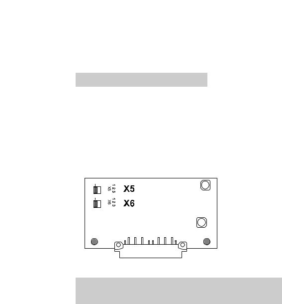
Jumper settings on the Modbus printed circuit board
|
|
|
|
|
|
|
|
|
|
|
|
|
|
|
|
|
|
|
|
|
|
|
|
|
|
|
|
|
|
|
|
|
|
|
|
|
|
|
|
|
|
|
|
|
|
|
|
|
|
|
|
|
|
|
|
|
|
|
|
|
|
|
|
|
|
|
|
|
|
|
|
|
|
|
|
|
|
|
|
|
|
|
|
|
|
|
|
|
|
|
|
|
|
|
|
|
|
|
|
|
|
|
|
|
Jumper position |
Description |
|||||||||||||||||||
|
|
|
|
|
|
|
|
|
|
|
|
|
|
|
|
|
|
|
|
|
X5 |
|
X6 |
|
|
|
|
|
|
|
|
||||||||||
|
|
|
|
|
|
|
|
|
|
|
|
|
|
|
|
|
|
|
|
|
1-2 |
|
|
|
|
1-2 |
|
|
|
|
With termination and polarization |
||||||||||
|
|
|
|
|
|
|
|
|
|
|
|
|
|
|
|
|
|
|
|
|
2-3 |
|
|
|
|
2-3 |
|
|
|
|
Without termination and polarization |
||||||||||
|
|
|
|
|
|
|
|
|
|
|
|
|
|
|
|
|
|
|
|
|
11/2009 - 4000744801 - AD Modbus MFC 300 R01 en |
www.krohne.com |
7 |

6 MODBUS PROTOCOL |
|
|
MFC 300 |
|
|
|
|
|
6.1 General information concerning the protocol
Using RTU (Remote Terminal Unit) format, data is transmitted as 8 bit binary characters. There are no special characters to determine the start and end of a message frame.
Synchronization is achieved by a minimum silent period of at least 3.5 character times before the start of each frame transmission and a maximum silent period of 1.5 character times between characters in the same frame.
6.2 RTU frame format
The format of the query and response frames vary slightly depending upon the command function. The basic form is outlined below.
Command function |
Frame format |
Description |
|
|
|
Silent period |
3.5 x T |
All transmissions must be preceded by a minimum silent |
|
|
period of 3.5 x T, where T is the transmission time of a |
|
|
single character. This can be calculated from the baud |
|
|
rate, e.g. at 19.2 kb no parity with 1 stop bit (10 bits), |
|
|
T = 520 µs. |
Slave address |
8 bits |
This is a single byte slave address which is transmitted |
|
|
first and must be in the range of 1...247. Address 0 is |
|
|
reserved for a broadcast address which all slaves should |
|
|
recognize, and therefore requires no response. |
|
|
|
Function code |
8 bits |
This is an eight bit code in the range of 1...255 although |
|
|
only 126 functions exist as the codes 129...255 represent |
|
|
an error condition. An error condition occurs when the |
|
|
addressed slave does not accept the command, in which |
|
|
case it responds with the function code + 128, i.e. with its |
|
|
MSB set to 1. |
|
|
|
Register start address or |
8 bit byte count |
Register start address: for a query command that requires |
byte count when required |
16 bit address |
data to be returned, this field will contain the 16 bit start |
|
|
address of the register (or data) to be returned. |
|
|
Note that the converter uses protocol addresses. |
|
|
Therefore the register address listed is the actual number |
|
|
required in the Modbus command. |
|
|
E.g: to access input register 30006, the register start |
|
|
address is 30006dec = 7536hex. |
|
|
Byte count: In general this is only present in frames that |
|
|
are transferring data, and has a value equal to the number |
|
|
of bytes contained in the data field. The data field is limited |
|
|
to a maximum of 250 bytes. |
|
|
|
Number of points or data |
n × 8 bits |
Number of points: for a query command that requires data |
bytes when required |
|
to be returned, this field will contain the number of |
|
|
registers to be returned regardless of their bit size. |
|
|
Data bytes: contains the data requested. The converter can |
|
|
use big endian format (MSB first) or little endian |
|
|
format (LSB first). |
|
|
|
CRC |
16 bits |
This field contains a 16 bit CRC which is calculated on all |
|
|
the data bits of the message bytes. |
|
|
|
8 |
www.krohne.com |
11/2009 - 4000744801 - AD Modbus MFC 300 R01 en |
 Loading...