


IFC090 FF 01/2006 |
7.10025.21.00 |
|
|
|
|
|
|
|
|
|
|
|
|
|
|
|
|
|
|
|
|
|
|
|
|
|
|
|
|
Supplementary
Installation and
Operating Instructions
IFC 090, IFC 090 i
With FOUNDATION
FIELDBUS Communication
KROHNE Messtechnik GmbH & Co. KG
Tel.: 0203-301 309 Fax: 0203-301389

Supplementary Documentation |
Page 2 of 44 |
||
IFC090, IFC090 i with FF |
|
||
IFC090 FF 01/2006 |
|
|
|
|
|
||
|
|
|
|
|
|
|
|
|
|
|
|
|
|
|
|
Contents:
1 |
Introduction |
4 |
|
2 |
Installation and Operation |
4 |
|
|
2.1 |
Technical Data IFC090 FF |
4 |
|
2.2 |
Electrical Connection of Foundation Fieldbus Devices |
4 |
|
2.3 |
Installation in the Hazardous Area, Bus Cable |
5 |
|
2.4 |
Shielding and Grounding |
6 |
|
2.5 |
IFC090 Menu Settings for Foundation Fieldbus |
6 |
|
2.6 |
Foundation Fieldbus Functional Blocks |
6 |
3 |
Foundation Fieldbus Principles |
7 |
|
|
3.1 |
Resource Block |
7 |
|
3.2 |
Transducer Block |
8 |
|
3.3 |
Function Blocks |
8 |
4 |
IFC090-FF Block Description |
9 |
|
|
4.1 |
Resource Block |
10 |
|
4.2 |
Transducer Block |
14 |
|
4.3 |
Analog Input Block (Flow) |
16 |
|
4.4 |
Integrator Blocks 1 and 2 (Flow(+)- and Flow(-)-Totalizer) |
22 |
5 |
IFC090-FF Configuration |
28 |
|
|
5.1 |
Resource Block Configuration |
28 |
|
5.1.1 |
Resource Block Mode Handling |
28 |
|
5.1.2 |
Write Protection |
28 |
|
5.1.3 |
Resource State Re-Initialization |
29 |
|
5.2 |
Transducer Block Configuration |
29 |
|
5.2.1 |
Transducer Block Mode Handling |
30 |
|
5.2.2 |
IFC090-FF Zero Point Calibration |
30 |
|
5.3 |
Analog Input Block Configuration |
30 |
|
5.3.1 |
Process Value Selection |
31 |
|
5.3.2 |
Linearization and Scaling |
31 |
|
5.3.3 |
Filtering |
32 |
|
5.3.4 |
Input/Output Options |
32 |
|
5.3.5 |
Output Status Options |
32 |
|
5.3.6 |
Process Alarms |
33 |
|
5.4 |
Integrator Blocks Configuration |
34 |
|
5.4.1 |
Integrator Block Mode Handling |
34 |
|
5.4.2 |
Integration Input – Rate or Accumulated Pulses |
34 |
|
5.4.3 |
Adaptation of Integrator Inputs |
34 |
|
5.4.4 |
Setting the Flow Direction |
36 |
|
5.4.5 |
Type of Integration |
36 |
|
5.4.6 |
Integrator Reset Strategies |
37 |
|
5.4.7 |
Trip and Pre-trip Handling |
39 |
|
5.4.8 |
Status Handling |
39 |
|
5.4.9 |
Input Value Handling |
39 |
KROHNE Messtechnik GmbH & Co. KG · Ludwig-Krohne-Str. 5 D-47058 Duisburg Tel.: 0203-301 309 Fax: 0203-301389 · E-mail: krohne@krohne.de

Supplementary Documentation |
Page 3 of 44 |
||
IFC090, IFC090 i with FF |
|
||
IFC090 FF 01/2006 |
|
|
|
|
|
||
|
|
|
|
|
|
|
|
|
|
|
|
|
|
|
|
6 Troubleshooting |
42 |
|
6.1 |
BLOCK_ERROR |
42 |
6.1.1 |
Resource Block |
42 |
6.1.2 |
Transducer Block |
42 |
6.1.3 |
Analog Input Block |
43 |
6.1.4 |
Integrator Blocks |
44 |
6.2 |
Transducer Block XD_ERROR |
44 |
6.3 |
Measurement Value Status |
44 |
KROHNE Messtechnik GmbH & Co. KG · Ludwig-Krohne-Str. 5 D-47058 Duisburg Tel.: 0203-301 309 Fax: 0203-301389 · E-mail: krohne@krohne.de

Supplementary Documentation |
|
Page 4 of 44 |
|
IFC090, IFC090 i with FF |
|
|
|
IFC090 FF 01/2006 |
Introduction |
||
|
|
||
|
|
||
|
|
|
|
|
|
|
|
|
|
|
|
|
|
|
|
1 Introduction
These instructions are supplementary to the “Installation and Operating Instructions IFC 090 K / F“. The details depicted therein, in particular the Safety Information are valid and should be adhered to. The present Supplementary Instructions provide additional information for the devices when being operated and connected to a Foundation Fieldbus.
Note: Please set the controller to manual mode before changing parameters of the IFC 090.
The present Supplementary Instruction for the IFC 090 with Foundation Fieldbusinterface, plus a diskette with the DD and CCF file are included in our scope of supply, in addition to those items delivered for the standard device.
2 Installation and Operation
2.1Technical Data IFC090 FF
Hardware |
|
Physical |
to IEC 61158-2 and the FISCO model |
Bus characteristics: |
9... 30 V; 0.3 A max.; 4.2 W max. |
Base current |
10 mA |
FDE |
bus with separate fault detection electronics |
Fault current |
6 mA; (fault current = max. continuous current – base current) |
Starting current |
lower than the base current |
“Ex“ approval |
EEx ia IIC T6 or EEx ib IIC/IIB T6 in conformity with the FISCO model |
Connection |
independent of polarity |
Software |
|
DD, CFF File |
supplied on diskette, available also in the KROHNE Downlaod Center |
Functional blocks |
flow [m3/s], integrator 1 [m3], integrator 2 [m3]; units are default units |
Operator control |
local display and operator interface at device |
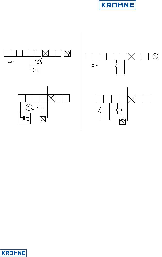
2.2Electrical Connection of Foundation Fieldbus Devices
Connect the bus cable as shown in the figure.
•Connect the cable cores to terminals D and DI.. Polarity reversal will not have any effect.
•The cable shield should be connected with minimum length to the FE functional ground.
•The equipotential bonding conductor must be connected to the device by connecting it to FE functional ground.
KROHNE Messtechnik GmbH & Co. KG · Ludwig-Krohne-Str. 5 D-47058 Duisburg Tel.: 0203-301 309 Fax: 0203-301389 · E-mail: krohne@krohne.de
Supplementary Documentation |
|
|
Page 5 of 44 |
|
IFC090, IFC090 i with FF |
|
|
|
|
IFC090 FF 01/2006 |
Installation and Operation |
|||
|
|
|
||
|
|
|
||
|
|
|
|
|
|
|
|
|
|
|
|
|
|
|
|
|
|
|
|
Foundation Fieldbus with Current Output (passive) Non Ex Version
|
current |
power- |
FE |
fieldbus |
output |
supply |
D |
|
D |
|
|
|
|
I |
|
|
|
I |
|
|
|
|
|
|
|||
|
|
|
|
|
|
|
|
|
||||||||||||
|
|
|
|
|
|
|
|
|
|
|
|
|||||||||
|
|
|
|
|
|
|
|
|
|
|
|
|
|
|
|
|
|
|
|
|
|
|
|
|
|
|
|
|
|
|
|
U min |
|
|
|||||||
|
|
|
|
|
|
|
|
|
|
|
|
|
||||||||
|
|
|
|
|
FE |
4-20mA |
= 8V |
|
|
|||||||||||
|
|
|
|
|
|
|
|
|
|
|
|
|
|
|
|
|
||||
|
|
|
|
|
|
|
|
|
|
|
|
|
|
|
|
|
||||
bus- |
|
|
|
|
|
|
|
|
|
|
|
|
||||||||
connection |
|
|
|
|
|
|
|
|
|
|
|
|
||||||||
|
|
|
|
|
|
|
|
|
|
|
|
|
|
|
|
|
|
|
|
|
|
|
|
|
|
|
|
|
|
|
|
|
|
|
|
|
|
|
|
|
|
U max = 30V
Outputs intrinsically safe
current |
fieldbus |
power |
||||||||||
output |
supply |
|||||||||||
I |
|
|
|
I |
D |
D |
|
|
|
|
||
|
|
|
|
|
|
|
|
|
|
|
|
|
|
U min |
|
4-20mA |
= 8V |
|
|
|
busconnection
U max = 30V
Foundation Fieldbus with Binary Output (passive) Non Ex Version
|
|
|
|
|
|
|
|
|
|
|
|
|
|
|
|
switching |
|
power- |
FE |
|||||||||
|
fieldbus |
|
output |
|
supply |
|||||||||||||||||||||||
|
|
|
|
|
|
|
|
|
|
|
|
|
|
|
|
|
|
|
|
|
|
|
|
|
|
|
|
|
|
D |
D |
|
|
|
|
|
|
|
|
|
B1 |
B1 |
|
|
|
|
|
|
|
||||||||
|
|
|
|
|
|
|
|
|
|
|
|
|
|
|
||||||||||||||
|
|
|
|
|
|
|
|
|
|
|
|
|
|
|
|
|
|
|
|
|
|
|
|
|
|
|
|
|
|
|
|
|
|
|
|
|
FE |
|
|
|
|
|
|
|
|
|
|
|
|
|
|||||||
|
|
|
|
|
|
|
|
|
|
|
|
|
|
|
|
|
|
|
|
|
||||||||
|
|
|
|
|
|
|
|
|
|
|
|
|
|
|
|
|
|
|
|
|
|
|
|
|||||
|
bus- |
|
|
|
|
|
|
|
|
|
|
|
|
|
||||||||||||||
|
connection |
|
|
|
|
|
|
|
|
|
|
|
|
|
||||||||||||||
|
|
|
|
|
|
|
|
|
|
|
|
|
|
|
|
|
|
|
|
|
|
|
|
|
|
|
|
|
Outputs intrinsically safe |
|
|
|
|
||||||||||||||||||||||||
|
|
|
|
|
switching |
|
|
|
|
|
|
|
|
|
|
power |
|
|||||||||||
|
|
|
|
|
|
|
|
output |
|
fieldbus |
|
supply |
|
|||||||||||||||
|
|
|
|
|
|
|
B1 |
B1 |
|
|
|
D |
D |
|
|
|
|
|
|
|
|
|||||||
|
|
|
|
|
|
|
|
|
|
|
|
|
|
|
||||||||||||||
|
|
|
|
|
|
|
|
|
|
|
|
|
|
|
|
|
|
|
|
|
|
|
|
|
|
|
|
|
busconnection
1
2.3Installation in the Hazardous Area, Bus Cable
We recommend that a Foundation Fieldbus network in the hazardous area should be projected in accordance with PTB’s FISCO model. The FISCO-Model is based on the following conditions:
•all electrical components which should be connected to the bus must be approved according to the FISCO model (even the termination)
•the maximum cable length should not exceed 1000 m,
•the values of the cable are within the following ranges: R´=15...150Ω/km; L´=0,4...1mH/km; C´=80...200nF/km, other limitations for the cable than the FISCO limitations are not existent. Nevertheless, a twisted pair and shielded cable is strongly recommended. Example: a good quality cable could have the following data: 44Ω/km, <90nF/km, <3dB attenuation at 39 kHz and 100 Ohm impedance at 31,25kHz.
•the approved input values of the field devices (Uo, Io, Po) comply to the output values of the power supply (e.g. segment coupler) according to UI ≤ Uo, II ≤ Io und PI ≤ Po.
KROHNE Messtechnik GmbH & Co. KG · Ludwig-Krohne-Str. 5 D-47058 Duisburg Tel.: 0203-301 309 Fax: 0203-301389 · E-mail: krohne@krohne.de

Supplementary Documentation |
|
|
Page 6 of 44 |
|
IFC090, IFC090 i with FF |
|
|
|
|
IFC090 FF 01/2006 |
Installation and Operation |
|||
|
|
|
||
|
|
|
||
|
|
|
|
|
|
|
|
|
|
|
|
|
|
|
|
|
|
|
|
2.4Shielding and Grounding
For optimum electromagnetic compatibility of systems it is extremely important that the system components, and particularly the bus cables connecting the components, are shielded and that such shields - if possible - form an unbroken cover.
Hence, it follows that, for use in non-hazardous duty systems, the cable shield should be grounded as often as possible.
In “Ex“ systems an adequate equipotential bonding in the hazardous and non-hazardous location along the entire fieldbus installation is strongly recommended. Multiple grounding of the shield is of advantage.
Note: The use of twisted and shielded cables is strongly recommended, otherwise EMC protection of the IFC 090 cannot be assured.
2.5IFC090 Menu Settings for Foundation Fieldbus
(see also Section 4 in the Installation and Operating Instructions for the IFC090)
The following settings need to be made for operation of the IFC 090 on a Foundation Fieldbus network. Note that the address can be set by the service “set slave address” as well.
Function (Fct.) |
Description |
|
|
|
|
||
3.9 COM |
Select function for the communication port |
||
|
♦ OFF |
♦ HART |
♦ PROFI PA * |
|
|
|
|
• Note: * indicates Foundation Fieldbus Communication when selected
2.6Foundation Fieldbus Functional Blocks
The IFC090 supports the H1 Foundation Fieldbus Communication Standard FF-003-2.2-1-1, Version 1.4. Additionally, all relevant parameters in the device are offered via the FF interface. The IFC 090 defines the following functional blocks:
•Three Function Blocks (FB): One Analog Input-FB for flow and two integrator-FBs for integration. Reset function is possible.
•One Transducer Block for electromagnetic flow measurement.
•One standard Resource Block.
KROHNE Messtechnik GmbH & Co. KG · Ludwig-Krohne-Str. 5 D-47058 Duisburg Tel.: 0203-301 309 Fax: 0203-301389 · E-mail: krohne@krohne.de

Supplementary Documentation |
|
|
Page 7 of 44 |
|
IFC090, IFC090 i with FF |
|
|
|
|
IFC090 FF 01/2006 |
Foundation Fieldbus Principles |
|||
|
|
|
||
|
|
|
||
|
|
|
|
|
|
|
|
|
|
|
|
|
|
|
|
|
|
|
|
3 Foundation Fieldbus Principles
The Foundation Fieldbus is a Local Area Network (LAN) for connecting field devices like sensors and actuators. One of the main benefits of Foundation Fieldbus is line saving in comparison to the traditional 4 ... 20 mA technology.
The different device functions are implemented in a block-based scheme within a User Application. In this block scheme, a distinction is made between the following kinds of blocks (see Figure 1):
•Resource Block,
•Transducer Block(s) and
•Function Block(s).
Figure 1: Foundation Fieldbus block scheme
3.1Resource Block
Each FF device possesses exactly one Resource Block describing the specific features of the fieldbus device. The Resource Block is not related to any functional process of the device, but contains data that are specific for the device (e.g. device name, serial number, supported features, etc).
In addition, the Resource Block provides dynamic diagnostic data giving information on the current state of the hardware.
A basic set of Resource Block parameters is specified by Fieldbus Foundation (see FF-891, 3.1). This set can be extended by additional manufacturer specific parameters (the IFC090-FF possesses the Foundation specified parameters only).
KROHNE Messtechnik GmbH & Co. KG · Ludwig-Krohne-Str. 5 D-47058 Duisburg Tel.: 0203-301 309 Fax: 0203-301389 · E-mail: krohne@krohne.de

Supplementary Documentation |
|
|
Page 8 of 44 |
|
IFC090, IFC090 i with FF |
|
|
|
|
IFC090 FF 01/2006 |
Foundation Fieldbus Principles |
|||
|
|
|
||
|
|
|
||
|
|
|
|
|
|
|
|
|
|
|
|
|
|
|
|
|
|
|
|
3.2Transducer Block
Transducer Blocks represent the interface between the device specific hardware (i.e. input/output functions) and the FF specified Function Block model. Since there might be multiple functions in a device (measurement values, positioning functions, etc), an FF device can have several Transducer Blocks1.
They provide device specific information in terms of sensor/actuator functions (e.g. type of sensor, range of process value, etc) and they make available the process values to the function blocks or provide the actuator input values obtained from function blocks to the hardware respectively.
3.3Function Blocks
The main functional behavior of the FF device is implemented in one or several Function Blocks. Depending on the device type there are Input Blocks (e.g. flow device → Analog Input Block, Discrete Input, etc), Output Blocks (e.g. valve → Discrete Input, etc), or Control Blocks (PID, etc). These blocks have input and/or output parameters to be linked to other devices and to control systems by the Fieldbus.
1 Note: This does not imply that an FF device has to have several Transducer Blocks if it provides several functions.
KROHNE Messtechnik GmbH & Co. KG · Ludwig-Krohne-Str. 5 D-47058 Duisburg Tel.: 0203-301 309 Fax: 0203-301389 · E-mail: krohne@krohne.de
Supplementary Documentation |
|
|
Page 9 of 44 |
|
IFC090, IFC090 i with FF |
|
|
|
|
IFC090 FF 01/2006 |
IFC090-FF Block Description |
|||
|
|
|
||
|
|
|
||
|
|
|
|
|
|
|
|
|
|
|
|
|
|
|
|
|
|
|
|
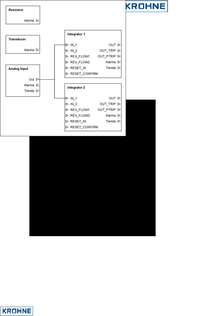
4 IFC090-FF Block Description
The IFC090-FF consists of the following blocks (see figure 2):
•1 Resource Block,
•1 Transducer Block (standard flow),
•1 Analog Input Block (flow value) and
•2 Integrator Blocks (1 for positiveand 1 for negative flow integration)
Figure 2: IFC090-FF block scheme
In the following, the different block parameters are described in detail.
KROHNE Messtechnik GmbH & Co. KG · Ludwig-Krohne-Str. 5 D-47058 Duisburg Tel.: 0203-301 309 Fax: 0203-301389 · E-mail: krohne@krohne.de

Supplementary Documentation |
|
|
Page 10 of 44 |
|
IFC090, IFC090 i with FF |
|
|
|
|
IFC090 FF 01/2006 |
IFC090-FF Block Description |
|||
|
|
|
||
|
|
|
||
|
|
|
|
|
|
|
|
|
|
|
|
|
|
|
|
|
|
|
|
4.1Resource Block
Table 1 lists the Resource Block parameters in alphabetical order (this list provides a description of the various parameters only; for a more detailed description of how to configure these parameters: see chapter below.
Parameter |
Access |
ACK_OPTION |
R/W |
ALARM_SUM Mix
ALERT_KEY |
R/W |
|
|
BLOCK_ALM |
R |
BLOCK_ERR R
CLR_FSTATE R/W
CONFIRM_TIME R/W
Description
Allows to enable automatic acknowledge of Resource Block alarms. The following settings are valid for Resource Block:
Unack Alarm 1 |
(Discrete Alarm) |
clearing of soft write lock |
Unack Alarm 8 |
(Block Alarm) |
block mode switches to Out of Service |
If set, the respective alarm doesn’t have to be acknowledged when occurring.
see also: ALARM_SUM, WRITE_LOCK, WRITE_ALM
Display of process alarms. The current alarm is displayed in the current field and can have the following values:
Discrete Alarm the soft write lock was cleared
Block Alarm block mode switches to Out of Service
The additional fields unacknowledged and unreported give respective information about the current alarm state. The field disabled, which is the only writable field of this parameter, can be used to disable these alarms.
see also: ACK_OPTION
ALERT_KEY parameter contains the identification number of the plant unit. It helps to identify the location (plant unit) of an event. The handling of this parameter is up to the control system or control person, respectively.
Display of current block state. Field subcode gives information about the state current errors. The following errors can occur:
Configuration Error
Change in Simulation Jumper Local Override
Device Fault State Memory Failure Lost Static Data Lost NV Data Power-up
Block was put Out of Service
The remaining fields give information about the state and the occurence of this alarm. Display of active block errors. The following errors are possible:
Out of Service |
block is in Out of Service mode |
Power-up |
power supply of IFC090-FF was interrupted |
Device needs Maintenance now |
fatal error of IFC090-FF hardware |
Memory Failure |
memory of device has errors |
Input Failure |
measurement value not o.k. |
Other |
any other hardware problem |
Writing a Clear to this parameter will clear the device fault state if the field condition, if any, has cleared.
NOTE:
This parameter is not supported! see also: FAULT_STATE
Time the resource waits for receipt confirmation of an earlier sent report, before trying to send a new one. If zero (0), no retry will be performed.
KROHNE Messtechnik GmbH & Co. KG · Ludwig-Krohne-Str. 5 D-47058 Duisburg Tel.: 0203-301 309 Fax: 0203-301389 · E-mail: krohne@krohne.de
Supplementary Documentation |
|
|
Page 11 of 44 |
|
IFC090, IFC090 i with FF |
|
|
|
|
IFC090 FF 01/2006 |
IFC090-FF Block Description |
|||
|
|
|
||
|
|
|
||
|
|
|
|
|
|
|
|
|
|
|
|
|
|
|
|
|
|
|
|
Parameter |
Access |
CYCLE_SEL |
R/W |
CYCLE_TYPE R
DD_RESOURCE R
DD_REV R
DEV_REV R
DEV_TYPE R
FAULT_STATE R
FEATURES R
FEATURE_SEL R/W
FREE_TIME R
FREE_SPACE R
GRANT_DENY R/W
HARD_TYPES R
ITK_VER R
LIM_NOTIFY R/W
Description
Used to select the block execution method for this resource. The following methods are available:
Scheduled
Completion of block execution
see also: CYCLE_TYPE
Identifies the block execution methods available for this resource.
It is possible to deliver devices which have the DD for its resource within the device. This parameter assigns the tag where to find the DD in the resource. Since the IFC090-FF doesn't come with a 'build-in' DD, this value is blank.
Revision associated with the DD of the resource – used by interface devices to locate the DD file for the resource.
KROHNE revision number associated with this resource – used by interface devices to locate the DD file for the resource.
KROHNE model number of the IFC090-FF – used by interface devices to locate the DD file for the resource.
Condition set by loss of communication to an output block.
NOTE:
Since the IFC090-FF doesn’t have an output block, this parameter isn’t supported. Used to show supported resource block options. The following features are supported by the IFC090-FF:
Reports
Soft Write Lock
see also: FEATURE_SEL
Used to select supported features. The following features are selectable:
Reports |
enable sending of alert reports |
Soft Write Lock |
enable soft write locking of parameters |
see also: FEATURE_SEL
Available time for configuration of further blocks.
NOTE:
Since the IFC090 blocks are preconfigured, this value is always zero (0). Available memory for configuration of further blocks.
NOTE:
Since the IFC090 blocks are preconfigured, this value is always zero (0).
Options for controlling access of host computer and local control panels to operating, tuning and alarm parameters of the block.
NOTE:
This parameter is not supported by IFC090-FF
The type available input signal that is delivered by the Transducer Block and used as Analog Input Block input parameter. For the IFC090-FF this is ‘Scalar Input’ (1).
Major revision number of the interoperability test case used in certifying this device as interoperable.
NOTE:
Due to an error, this value is ‘0’, but has to be ‘4’ (since the IFC090-FF is interoperable with interoperability test case version 4).
Maximum number of unconfirmed alert notifies messages allowed. This number always has to be less than MAX_NOTIFY.
see also: MAX_NOTIFY
KROHNE Messtechnik GmbH & Co. KG · Ludwig-Krohne-Str. 5 D-47058 Duisburg Tel.: 0203-301 309 Fax: 0203-301389 · E-mail: krohne@krohne.de

|
Supplementary Documentation |
|
|
Page 12 of 44 |
|||||||||
|
IFC090, IFC090 i with FF |
|
|
|
|
|
|
||||||
|
IFC090 FF 01/2006 |
|
|
|
|
IFC090-FF Block Description |
|||||||
|
|
|
|
|
|
|
|
|
|
|
|||
|
|
|
|
|
|
|
|
|
|
||||
|
|
|
|
|
|
|
|
|
|
|
|
|
|
|
|
|
|
|
|
|
|
|
|
|
|
|
|
|
|
|
|
|
|
|
|
|
|
|
|
||
|
|
|
|
|
|
|
|
|
|
|
|
|
|
|
|
|
|
|
|
|
|
|
|
|
|
||
|
Parameter |
|
|
Access |
|
|
Description |
|
|
|
|
||
|
MANUFAC_ID |
R |
|
Manufacturer identification number. For KROHNE devices this is always |
|
||||||||
|
|
|
|
|
|
|
|
00012C16 = 30010 = KROHNE |
|
|
|
||
|
MAX_NOTIFY |
R |
|
Maximum number of unconfirmed notifies messages possible. |
|||||||||
|
|
|
|
|
|
|
|
see also: LIM_NOTIFY |
|
|
|
|
|
|
MEMORY_SIZE |
|
R |
|
Available configuration memory in the empty resource. |
||||||||
|
|
|
|
|
|
|
|
NOTE: |
|
|
|
|
|
|
|
|
|
|
|
|
|
This parameter is not supported by IFC090. |
|||||
|
MIN_CYCLE_T |
R |
|
Time duration of the shortest cycle interval of which the IFC090 is capable. Within this |
|||||||||
|
|
|
|
|
|
|
|
cycle all Function Blocks (1 Analog Input + 2 Integrators) have to be executed for one |
|||||
|
|
|
|
|
|
|
|
time. |
|
|
|
|
|
|
MODE_BLK |
Mix |
|
Display of the current (actual), desired (target), possible (permitted) and normal modes |
|||||||||
|
|
|
|
|
|
|
|
of the Resource Block. By writing a permitted value to the target field, you can control |
|||||
|
|
|
|
|
|
|
|
the execution modes of the block. The following block modes are allowed for the |
|||||
|
|
|
|
|
|
|
|
IFC090-FF Resource Block: |
|
|
|
||
|
|
|
|
|
|
|
|
Automatic Mode (AUTO) |
|
|
|
||
|
|
|
|
|
|
|
|
In this mode, the complete resource is able to execute. All other blocks |
|||||
|
|
|
|
|
|
|
|
(Transducer, Analog Input, Integrator) can switch to a mode different from Out of |
|||||
|
|
|
|
|
|
|
|
Service) |
|
|
|
|
|
|
|
|
|
|
|
|
|
Out of Service (OOS) |
|
|
|
||
|
|
|
|
|
|
|
|
In this mode, the complete |
resource stops its execution. For the other blocks |
||||
|
|
|
|
|
|
|
|
it is not possible to switch to AUTO mode, unless the Resource Block does. |
|||||
|
|
|
|
|
|
|
|
NOTE: |
|
|
|
|
|
|
|
|
|
|
|
|
|
Under certain conditions (e.g. RS_STATE = ONLINE_LINKING) the Resource Block is |
|||||
|
|
|
|
|
|
|
|
not capable of switching to AUTO mode. |
|||||
|
|
|
|
|
|
|
|
see also: RS_STATE |
|
|
|
|
|
|
NV_CYCLE_T |
R |
|
Minimum time interval between two cycles of writing non-volatile parameters OUT, PV |
|||||||||
|
|
|
|
|
|
|
|
and FIELD_VAL. Since these values are not saved, this value is always zero (0) which |
|||||
|
|
|
|
|
|
|
|
means don’t save these parameters. |
|||||
|
RESTART |
|
R/W |
|
Allows a manual restart to be initiated. Several degrees of restart are possible: |
||||||||
|
|
|
|
|
|
|
|
RUN |
|
Setting for normal operation. |
|||
|
|
|
|
|
|
|
|
RESTART RESOURCE |
Warm start of the IFC090-FF. |
||||
|
|
|
|
|
|
|
|
RESTART WITH DEFAULTS |
Sets all FF parameters to their default values. |
||||
|
|
|
|
|
|
|
|
|
|
|
To be used with caution! |
||
|
|
|
|
|
|
|
|
RESTART PROCESSOR |
Cold start of IFC090 measurement electronics |
||||
|
|
|
|
|
|
|
|
|
|
|
and warm start of FF process. |
||
|
RS_STATE |
R |
|
State of the function block application state machine. The following states are possible: |
|||||||||
|
|
|
|
|
|
|
|
ONLINE |
Normal operation state: All defined links are established. |
||||
|
|
|
|
|
|
|
|
INITIALIZATION |
Initialization state: All alarms will be confirmed and |
||||
|
|
|
|
|
|
|
|
|
|
acknowledged. |
|||
|
|
|
|
|
|
|
|
ONLINE-LINKING Link evaluation state: Wait until all links are established |
|||||
|
|
|
|
|
|
|
|
STANDBY |
Out of Service state: Entered if mode of Resource Block is |
||||
|
|
|
|
|
|
|
|
|
|
OOS. |
|
|
|
|
SET_FSTATE |
|
R/W |
|
Allows the Fault State conditions for output function blocks to be manually initiated by |
||||||||
|
|
|
|
|
|
|
|
setting to ‘Set’. |
|
|
|
|
|
|
|
|
|
|
|
|
|
NOTE: |
|
|
|
|
|
|
|
|
|
|
|
|
|
Since the IFC090-FF doesn’t have an output block, this parameter is not supported. |
|||||
|
SHED_RCAS |
|
R/W |
|
Time duration for the monitoring-cycle in which a function block in mode RCAS has to |
||||||||
|
|
|
|
|
|
|
|
answer on control system requests. |
|||||
|
|
|
|
|
|
|
|
NOTE: |
|
|
|
|
|
|
|
|
|
|
|
|
|
Since the IFC090-FF has no function block capable of switching to mode RCas, this |
|||||
|
|
|
|
|
|
|
|
parameter is not supported. |
|
|
|
||
KROHNE Messtechnik GmbH & Co. KG · Ludwig-Krohne-Str. 5 D-47058 Duisburg Tel.: 0203-301 309 Fax: 0203-301389 · E-mail: krohne@krohne.de

Supplementary Documentation |
|
|
Page 13 of 44 |
|
IFC090, IFC090 i with FF |
|
|
|
|
IFC090 FF 01/2006 |
IFC090-FF Block Description |
|||
|
|
|
||
|
|
|
||
|
|
|
|
|
|
|
|
|
|
|
|
|
|
|
|
|
|
|
|
Parameter |
Access |
SHED_ROUT |
R/W |
|
|
STRATEGY |
R/W |
|
|
ST_REV |
R |
|
|
TAG_DESC |
R/W |
|
|
TEST_RW |
R/W |
|
|
UPDATE_EVT |
R |
|
|
WRITE_ALM |
R |
|
|
WRITE_LOCK |
R/W |
|
|
WRITE_PRI |
R/W |
|
|
Description
Time duration for the monitoring-cycle in which a function block in mode Rout has to answer on control system requests.
NOTE:
Since the IFC090-FF has no function block capable of switching to mode Rout, this parameter is not supported.
Parameter used to group a set of blocks. This is done by assigning the same STRATEGY numerical value to all blocks belonging to one group.
NOTE:
This parameter is neither checked nor used by the function block application! It can be used by control system to group blocks!
Static data revision counter. ST_REV will be incremented if a static Resource Block parameter has changed. By checking this parameter, control systems are able to realize if a static parameter has changed its value without checking all static parameters all the time.
User description of the intended application of the block. The user is free in setting this value. The only limitation is the length of 32 characters at maximum. It is not checked by the application, but has informational character only.
Read/write test parameter. It is only used during Fieldbus Foundation interoperability testing and has no meaning for normal operation!
Alert generated by a change to static data. The subfields of this parameter give detailed information about the changed static parameter, time of change and state of the update event.
Alarm generated, if the parameter write lock is cleared.
see also: ACK_OPTION, WRITE_LOCK, WRITE_PRI
If this parameter is set to ‘Locked’ (2) all writable parameters in all blocks are write protected, with the exception of WRITE_LOCK itself. Dynamic data will continue to be updated.
To disable the write protection, set this parameter to ‘Not Locked’ (1).
see also: ACK_OPTION, WRITE_ALM, WRITE_PRI
Priority of the alarm generated by clearing the WRITE_LOCK:
0alarm isn't be evaluated
1no notification to the control system in case of an write protection alarm
2reserved for block alarms
3-7 write protection is send as user/operator note to the control system, according to the given priority (3 = low and 7 = high)
8-15 write protection alarm is sent with the appropriate priority (15 = high and 8 = low).
Table 1: Resource Block parameters
KROHNE Messtechnik GmbH & Co. KG · Ludwig-Krohne-Str. 5 D-47058 Duisburg Tel.: 0203-301 309 Fax: 0203-301389 · E-mail: krohne@krohne.de

Supplementary Documentation |
|
|
Page 14 of 44 |
|
IFC090, IFC090 i with FF |
|
|
|
|
IFC090 FF 01/2006 |
IFC090-FF Block Description |
|||
|
|
|
||
|
|
|
||
|
|
|
|
|
|
|
|
|
|
|
|
|
|
|
|
|
|
|
|
4.2Transducer Block
Table 2 lists the Transducer Block parameters in alphabetical order (this list gives a description of the various parameters only; see chapter below. for a detailed description depicting how to configure these parameters):
Parameter |
Access |
ALERT_KEY |
R/W |
|
|
BLOCK_ALM |
R |
|
|
BLOCK_ERR |
R |
|
|
CAL_MIN_SPAN |
R |
CAL_POINT_HI |
R/W |
|
|
CAL_POINT_LO |
R/W |
|
|
CAL_UNIT |
R/W |
|
|
CAL_ZEROPOINT |
R/W |
|
|
COLLECTION_DIRECTORY |
R |
|
|
CYCLES_ZEROPOINT_CAL |
R/W |
|
|
LIN_TYPE |
R/W |
|
|
Description
Identification number of the plant unit. It helps to identify the location (plant unit) of an event. The handling of this parameter is up to the control system or control person, respectively.
Display of current block state. Field subcode gives information about the state current errors. The following errors can occur:
Configuration Error
Block was put Out of Service
The remaining fields give information about the state and the occurrence of this alarm.
Display of active block errors. The following errors are possible:
Out of Service |
block is in Out of Service mode |
Device needs Maintenance now |
fatal error of IFC090-FF hardware |
Minimum calibrated span value allowed. |
|
Highest calibrated value. This value depends on the IFC090-FF pipe diameter.
Lowers calibrated value. This is the absolute value of the lowest positive and negative value, the device is capable of measuring, and it is constant to ‘0’. Engineering units code index for the calibration values. This is always m3/s (cubic meter per second).
Start zero point calibration by writing a value different from ‘0’.
NOTE:
Handle this parameter with caution, since a correct zero point calibration is based some important conditions.
Directory that specifies the number, starting index, and DD2 item IDs of the transducer block’s data collections. The first entry specifies the number of data collections, and the remaining specifies the data collections.
Number of cycles to perform if a zero point calibration is started. Valid values are in between 0 and 2000.
Linearization type used to describe the behavior of the sensor output. The IFC090-FF has a linearization type of ‘linear with input’.
2 DD = Device Description
KROHNE Messtechnik GmbH & Co. KG · Ludwig-Krohne-Str. 5 D-47058 Duisburg Tel.: 0203-301 309 Fax: 0203-301389 · E-mail: krohne@krohne.de
 Loading...