


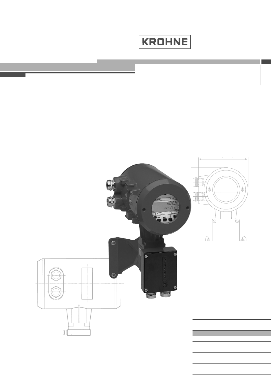
IFC-090F
Variable area flowmeters
Vortex flowmeters
Flow controllers
Electromagnetic flowmeters
Ultrasonic flowmeters
Mass flowmeters
Level measuring instruments
Communications technology
Engineering systems & solutions
Switches, counters, displays and recorders
Heat metering
Pressure and temperature
©KROHNE12 / 2002 7.30923.31.00
Addition to the
installation and operating instructions
IFC 090 F-EEx
IFC 090 F / i-EEx
Signal converters for
electromagnetic flowmeters
ALTOFLUX IFC 090 F-EEx and ALTOFLUX IFC 090 F / i-EEx 2
WARNING !
No changes regarding safety may be made to the devices. Unauthorized
changes might affect the explosion safety of the devices.
Be sure to follow these instructions !
IMPORTANT !
• The prescriptions and regulations as well as the electrical data
described in the EC-type examination certificate must be obeyed.
• Beside the instructions for electrical installations in non-hazardous
locations according to the applicable national standard (e.g. IEC 364),
especially the regulations in EN 60079-14 "Electrical installations in
hazardous locations" or equivalent national standard must be followed.
• Installation, establishment, utilization and maintenance are only allowed
to be executed by personnel with an education in explosion safety!
These additional instructions are an extension to the Installation and Operating Instructions and
only apply to the EEx version of the IFC 090 F - EEx or IFC 090 F / i -EEx signal converter. All
technical information described in the “Installation and Operating Instructions” are applicable, when
not specifically excluded, completed or replaced by the instructions in these additional instructions.
Contents
1 System components 3
1.1 General information 3
1.2 IFS x000 F-EEx primary head 3
1.3 IFC 090 / … -EEx signal converter 4
1.3.1 Electronic compartment 4
1.3.2 Terminal compartment 4
1.4 Data plates 5
1.5 Electronic unit 5
2 Electrical connection 7
2.1 Equipotential bonding system 7
2.2 Intermediate junction box ZD-EEx 7
2.3 Connecting cables 7
2.4 Connecting diagram 9
2.5 regular IFC 090 - EEx electronic unit 11
2.6 MODIS version IFC 090 I - EEx electronic unit 12
2.7 Connecting diagrams MODIS 13
3 Operation of the signal converter 20
4 Maintenance 20
5 Service 21
5.1 General information for replacements 21
5.2 Replacement of electronic unit 22
5.3 Repalcement of power fuses 24
5.4 Changing power supply voltage 27
6 Ordering information 28
7 Declaration of conformity 29
8 EC-type examination certificates 30
ALTOFLUX IFC 090 F-EEx and ALTOFLUX IFC 090 F / i-EEx 3
1 System components
1.1 General information
The ALTOFLUX IFC 090 F/…-EEx signal converter complies with the European Directive 94/9/EC
(ATEX 100a) and has been approved for hazardous classified locations of Zone 1 and 2 by the
KEMA conform the European Standards of the EN 500xx series. The IFC 090 F/…-EEx has the
following EC-type examination Certificate number:
KEMA 01 ATEX 2234
The signal converter is available in two types, namely:
IFC 090 F-EEx regular explosion protected version;
IFC 090 F/i-EEx, MODIS version. This type has intrinsically safe signal output circuits, which are
pro-vided by two installed MODIS modules (see Sect. 1.5 for details).
The regular IFC 090 F-EEx signal converter is designed for ambient temperatures in the range of
–40°C up to +60°C, the so-called MODIS version type IFC 090 F/i-EEx is rated for ambient
temperatures from -20°C up to +60°C. Both types of signal converters are in remote design, which
means that they are installed on a certain distance of the measuring unit, the IFS x000 F-EEx
series of primary heads. The primary heads are approved according to the European Directive
94/9/EC (ATEX 100a) as well. Due to the installation on a distance from the primary head, the
signal converter is independent of the process liquid temperature and therefore rated for
temperature class T6 and a T85ºC for dusts.
The IFC 090 F / … EEx signal converter is marked with the following code below:
Regular version II 2GD EEx de [ib] IIC T6
MODIS version II 2GD EEx de [ia] [ib] IIC T6
Also see the EC-type Examination Certificate in Sect. 8 of these instructions.
1.2 IFS x000 F-EEx primary head
The IFS x000 F-EEx series primary head is the measuring unit of the IFC 090 F/…-EEx signal
converter and contains two field coils and two electrodes in type of protection intrinsic safety
category "ib" according to EN 50020. The type of protection of the field coils depends on the meter
type and size, see the additional installation and operating instructions of the primary head
concerned.
The electrode circuits are wired by separate shielded cables and marked by the sheath color
(white and purple). The intrinsical safe "ib" electrode circuits inside the IFS x000 F-EEx primary
head have the following maximum values (entity parameters):
Maximum input voltage U
max
= 20 V
Maximum output current I
max
= 170 mA
Maximum internal capacitance C
i
= 0
Maximum internal inductance L
i
= 0
The two field coils inside the primary head are connected in series and provided with the type of
protection increased safety “e” conform to EN 50019 and additionally flameproof enclosure “d” in
accordance with EN 50018 or encapsulation “m” according to EN 50028. The coils have a
maximum resistance below 90 Ω per coil with a wire diameter of at least 0.25 mm and insulation
class H (T
max
≥ 180°C) according to IEC 85. The field coils are supplied with a square-wave signal
with a peak voltage of 60 V maximum and a nominal current of 125 mA. The coil circuit is
protected by two series fuses in the IFC 090 …-EEx electronics unit. The fuses are rated for a
maximum voltage of 250 Vac @ 50-60 Hz, have a breaking capacity of at least 35 A and switching
characteristics fast (F) to time-lag (T).
ALTOFLUX IFC 090 F-EEx and ALTOFLUX IFC 090 F / i-EEx 4
1.3 IFC 090/…-EEx signal converter
The IFC 090/…-EEx signal converter consists of the pre-certified cylindrical housing of die-casted
aluminum (type AX/P-EEx with KEMA No. Ex-99.E.8128 U). It has two separate compartments,
divided from each other by an integrated wall with casted flameproof terminal feed-through. The
neck at the bottom of the housing that is connected to the wall-mounting bracket with junction box,
contains flameproof cable feed-through type LC-2/EEx, which is approved by KEMA under No.
Ex-01.E.2036 U. The wall-mounting bracket and junction box are also made of die-casted
aluminium. The signal converter housing is on both ends closed by a cylindrical cover with
M115x2-6H6g screw-thread and O-ring sealing. The signal converter has an ingress protection
degree of IP 65 / IP 67 conform to EN 60529.
1.3.1 Electronics compartment
The electronics compartment accommodates the pre-certified IFC 090…-EEx electronics unit with
approval number PTB 98 ATEX 2012 U. The compartment is designed with type of protection
flameproof enclosure "d" according to EN 50018 and closed by a threaded flameproof display
cover. The IFC 090…-EEx unit is inserted into the electronics compartment via two sliding rubbers
that position and fixate it at the front in the housing. Two M4 screws mount the unit and a third M4
screw fixates the copper earth strip at the back-end of the safety barrier printed circuit board. The
three screws are screwed to the integrated aluminium wall in-between terminal and electronics
compartment. The safety barrier provides the electrodes inside the primary head with type of
protection intrinsic safety “ib” according to EN 50020.
See tables on the next pages for the electrical data of the available power supplies (e.g. mains
voltages, etc.). The safety barrier has the following maximum values (entity parameters):
Maximum output voltage U
0
= 9 V
Maximum output current I
0
= 38 mA
Maximum allowed external capacitance C
0
= 4.9 µF
Maximum allowed external inductance L
0
= 23 mH
1.3.2 Terminal compartment
The terminal compartment has seven M4 clamp terminals for connection of the power supply and
signal output circuits (binary and current outputs). Section 2 shows the terminal arrangement for
the regular and MODIS version of the IFC 090/…-EEx signal converter. The terminals are
separated from each other by insulation plates (nine in total, one at each end). The terminal
arrangement of the MODIS version (i.e. IFC 090i-EEx) is shown in Sect. 2.6. Two of the terminals
are used for connection of the non-intrinsically safe power supply and four terminals (marked with
"*") for the intrinsically safe, category "ia" signal outputs (i.e. current, pulse resp. status output) of
the MODIS modules. The non-intrinsically and intrinsically safe terminals are separated from each
other by a metal dividing plate, which is screwed to the remaining (not connected) M4 terminal.
The two non-intrinsically safe power supply terminals are covered by an insulating plate.
The terminal compartment (with standard type of protection increased safety "e") is standard
equipped with two ATEX or E-generation approved "EEx e" cable glands. The terminal
compartment can also be provided as a flameproof enclosure "d", in which case ATEX or E-
generation approved "EEx d" cable glands of size Pg13.5, Pg16 or M20x1.5 are factory installed
or must be installed by the customer. For flameproof conduit systems, the terminal compartment
must have type of protection flameproof enclosure "d" according to EN 50018. The conduits must
be sealed by "EEx d" approved (within the ATEX 100a directive) sealing devices (i.e. stopping
box) directly at the conduit entrances of the as flameproof enclosure performed terminal
compartment. All used cable glands, blind plugs and sealing devices for conduit systems must
have an ingress protection degree of IP65 or better.
ALTOFLUX IFC 090 F-EEx and ALTOFLUX IFC 090 F / i-EEx 5
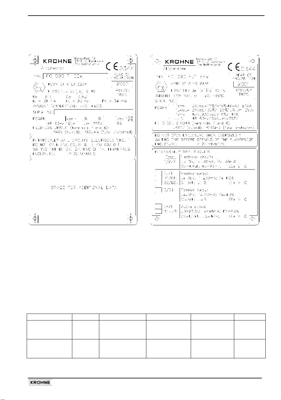
1.4 Data plates
IFC 090 F-EEx IFC 090 F / i-EEx
1.5 Electronics unit
The IFC 090 F/…-EEx signal converter can be equipped with the regular IFC 090-EEx electronics
unit or with the IFC 090i-EEx electronics unit with intrinsically safe signal outputs (i.e. MODIS
version). The regular signal converter design has type designation IFC 090 F-EEx and the MODIS
version is designated as IFC 090 F/i-EEx.
Regular IFC 090-EEx electronics unit
The IFC 090-EEx can be equipped with one of the following power supplies, which depends on
the mains supply voltage in area of application.
Electrical data of power supply
Power supply Terminal Description Supply voltage Tolerance Power
AC-versions
L
N
PE
Live
Neutral
Protective Earth
115/230 Vac
100/200 Vac
-15%/+10% 10 VA
AC/DC-version
1L
0L
FE
Live
Neutral
Functional Earth
24V ac/dc
AC: -15%/+10%
DC: -25%/+30%
AC: 10 VA
DC: 8 W
The above listed power supplies are protected by a mains fuse rated according the next table.
ALTOFLUX IFC 090 F-EEx and ALTOFLUX IFC 090 F / i-EEx 6
Mains fuses
Power supply Mains fuse
Type Nominal voltage Rating Specifications
100/115 Vac 200 mA Switching char.: fast (F) to time-lag (T)
200/230 Vac 125 mA
Breaking capacity: ≥ 1500 A @ 250 V
AC-versions
24 Vac Switching char.: fast (F) to time-lag (T)
DC-version
24 Vdc
1.25 A
Breaking capacity: ≥ 300 A @ 65 V
The IFC 090-EEx electronics unit is equipped with the following in-/output circuits. Terminals B1,
B⊥ and B2 can be configured as status or pulse outputs or as control inputs via the software. See
the table below for the electrical data of these in-/output circuits.
Electrical data of in-/output circuits
Terminals Description
Nominal voltage Maximum current
B1, B⊥, B2
Pulse, status, control in-/outputs 32 V 150 mA
I+, I Current output 15 V 22 mA
The difference between 115/230 Vac version and the 100/200 Vac version is the number of the
primary windings of the mains transformer.
The terminals indicated as B1, B⊥ and B2 can be configured as pulse in-/outputs by jumpers.
The IFC 090-EEx electronics unit is provided with an extension module that is used for data
communication (e.g. SMART, HART or RS485). In that case, the current output signal (I+, I) is
superposed with a sinusoidal voltage signal of 0.5 V. The extension module does not significantly
influence the nominal voltage U
n
, the nominal current I
n
or the power dissipation.
Overheating protection
The mains transformer is protected against overheating by a temperature breaker in series with
the primary winding. The temperature breaker is casted within the compound of the transformer
and has an opening temperature of 125 °C (± 5 K).
IFC 090i-EEx unit with MODIS modules
The IFC 090i-EEx electronics unit is equipped with two MODIS-modules. It is equipped with one of
the following power supplies.
Electrical data of IFC 090i-EEx electronics unit
Power supply Terminal Function Electrical data
AC-version
L
N
PE
Live
Neutral
Protective ground
U
n
= 100…230 Vac –15%/+10%
P
n
= approx. 15 VA
Primary fuse: Rated current: 1.6 A
Design conform IEC 127-2
Breaking capacity: 1500 A
AC/DC-version
1L
0L
FE
Live
Neutral
Functional ground
U
n
= 24 V ac / dc
AC: -15%/+10% or 20.4…26.4 V ac
DC: -25% / +30% or 18…32 V dc
I
n
= approx. 490…630 mA for AC
approx. 310…550 mA for DC
P
n
= approx. 10 W
Primary fuse: Rated current: 1.25 A
Design conform IEC 127-2
Breaking capacity: 1500 A
NOTE:
The mains fuses for both electronics units are listed in Sect. 6 of this manual.
ALTOFLUX IFC 090 F-EEx and ALTOFLUX IFC 090 F / i-EEx 7
2 Electrical connection
2.1 Equipotential bonding system
The IFC 090 F/…-EEx signal converter must always be incorporated into the equipotential
bonding system of the hazardous area. This connection can be achieved through the PE/FE
conductor connected to the PE terminal in the terminal compartment (see figure of terminal
arrangement) or through a separate PE conductor, cross sectional area at least 4 mm
2
, connected
to the external PE clamp, placed below the converter housing.
2.2 Intermediate junction box ZD-EEx
For safety reasons, standard cables with a rubber or thermoplastic insulation sheath may only be
used up to a continuous operating temperature of 70°C at the cable entry and 80°C at the
branching point of the connecting cables. In case that the temperature at the above mentioned
parts exceed the maximum values, heat-resistant cables must be installed at the IFS x000 F-EEx
primary head in remote design. Also see the EC-type examination certificate of the primary head.
The table below summarizes the conditions for use of heat-resistant cables for the IFS x000 F-
EEx primary head.
Use of heat-resistant cables
Primary head Meter size Ambient temperature Process liquid temperature
DN25 - 150
≤ 40°C
≤ 50°C
≤ 60°C
not required
≥ 155°C
≥ 105°C
IFS 4000 F-EEx
≥ DN200 ≤ 40°C
≤ 50°C
≤ 60°C
not required
≥ 145°C
≥ 110°C
IFS 5000 F-EEx DN2.5 - 100
≤ 40°C
≤ 50°C
≤ 60°C
≥ 165°C
≥ 130°C
≥ 100°C
IFS 6000 F-EEx DN2.5 - 80
≤ 40°C
≤ 50°C
≤ 60°C
not required
≥ 160°C
≥ 115°C
In case that heat-resistant cables are required, install the intermediate junction box ZD-EEx at a
distance of approximately 5 m from the primary head. Connect heat-resistant cables (see cables
D and E in the next section) between the primary head’s junction box and the intermediate
junction box ZD-EEx. The standard cables (types B and C) can be used between the IFC 090
F/…-EEx signal converter and intermediate junction box. See connection diagram 2.
The silicone rubber insulated connection cable for the magnetic field coils must be protected
against mechanical damages between the primary head and intermediate junction box by a
conduit system with edge protections. Intermediate box ZD-EEx has terminals with type of
protection increased safety “e” conform to EN 50019. The intermediate box is incorporated in the
equipotential bonding system of the installation via its external clamp terminal.
2.3 Connecting cables
NOTE:
The following described cables are shown in the next connection diagrams.
Cable A
Signal cable for current output and binary outputs (pulse and status output): The cable parameters
must be in accordance with the regulations in the EN 60079-14 "Electrical installations in
hazardous locations" or an equivalent national standard. For the MODIS version with IFC 090i-
EEx electronics unit (right detail in connection diagram 1) the signal cable for the intrinsically safe
signal in-/outputs must also conform the requirements as specified in the relevant standard
national code of practice for the installation of electrical apparatus with type of protection Intrinsic
Safety "i".
ALTOFLUX IFC 090 F-EEx and ALTOFLUX IFC 090 F / i-EEx 8
Cable B
Power supply cable: The cable parameters must be in accordance with the regulations of the EN
60079-14 "Electrical installations in hazardous locations" or an equivalent national standard.
The PE terminal must be connected to the protective ground conductor of the mains supply.
Rated voltage
≥ 500 V
Cross-sectional area of core 1.5 to 2.5 mm
2
Examples H07...-., H05...-.
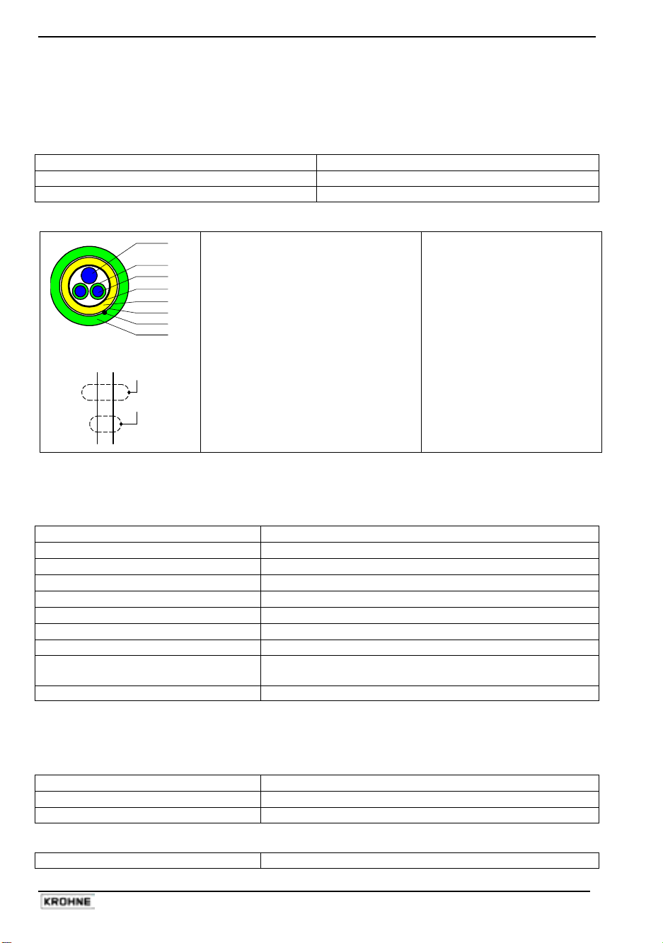
Cable C
1
2
3
4
5
6
7
8
3 3
7
1
6
4
Type DS blue
Intrinsical safe, with double shielding
1 Stranded drain wire,
1st shield, 1.5 mm
2
2 Insulation
3 Stranded wire, 0.5 mm
2
4 Special foil, 1st shield
5 Insulation
6 Mu-metal foil, 2nd shield
7 Stranded drain wire,
2nd shield, 0.5 mm
2
8 Outer sheath
(flame-retardant)
Cable constants (typical
values at Ta = 20°C)
C’3/3 60 pF/m (1 kHz)
C’3/4 110 pF/m (1 kHz)
C’4/6 290 pF/m (1 kHz)
L’3/3 0.85 µH/m (1 kHz)
L’3/4 0.60 µH/m (1 kHz)
R’3 37 mΩ/m
R’4+1 12 mΩ/m
Cable D
Intrinsical safe, with single shielding. Heat-resistant conform to VDE 0165/02.91.
Properties
Continuous service temperature
≥ 120°C
Test voltage
≥ 500 V
Capacitance:
≤ 200 pF/m
≤ 200 pF/m
Inductance:
≤ 1µH/m
Cable length
≤ 5 m
Single-wire-Ø:
≥ 0.1 mm
Cross-sectional area of core 0.5 to 1.5 mm
2
Sheath light-blue or in other way color-coded as intrinsical safe,
flame-retardant.
Example Silicone rubber insulated, shielded control cable.
Cable E
Non-intrinsical safe, 2-core without shielding. Heat-resistant conform to VDE 0165/02.91.
Properties
Continuous service temperature
≥ 120°C
Test voltage
≥ 500 V
Cross-sectional area of core 1.5 mm
2
Bonding conductor
Cross-sectional area Max. 4 mm
2
ALTOFLUX IFC 090 F-EEx and ALTOFLUX IFC 090 F / i-EEx 9
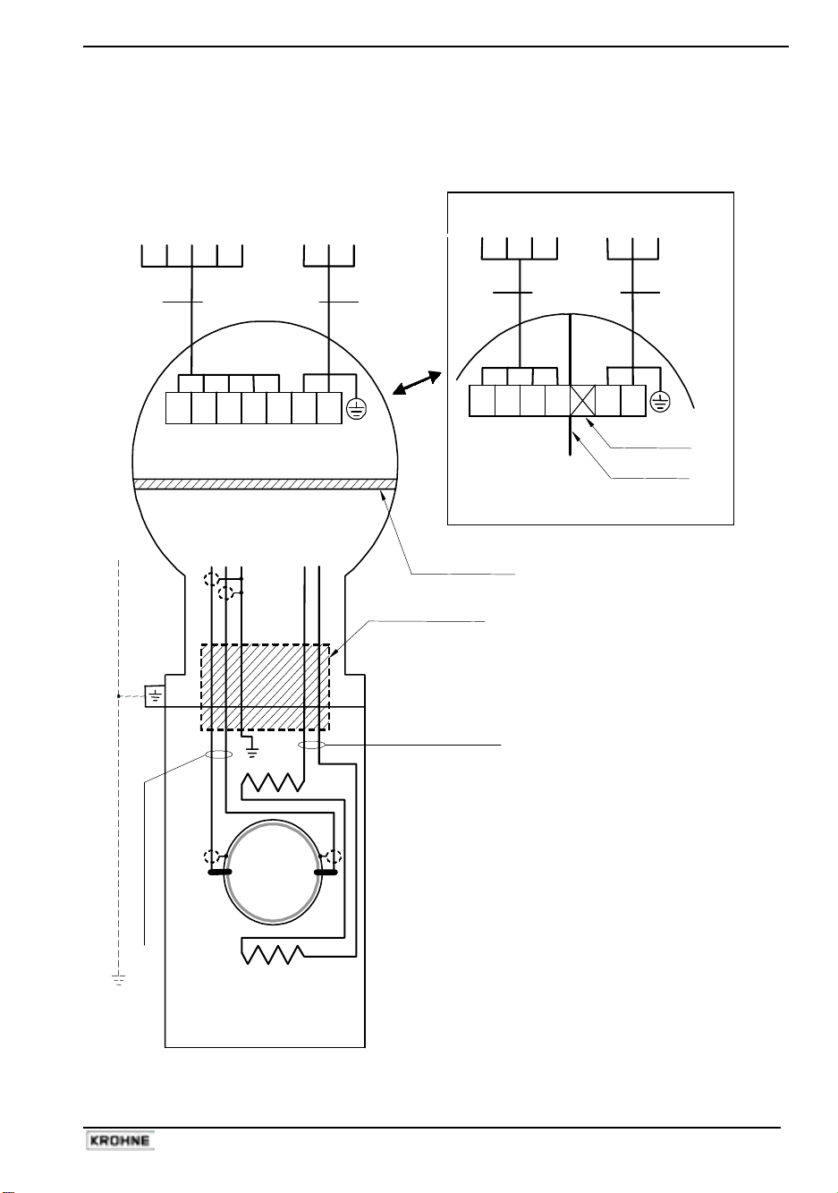
2.4 Connection diagrams
Connection diagram 1: Standard cables
Flow tube
Hazardous locations
of Zone 1 and 2
E
IFS x000…-EEx
Primary Head
Intrinsically safe electrode circuits
Increased safe field coil circuit
Coil
B1 B
⊥
B2 I+ I L N
BINARY CURRENT MAINS
OUTPUTS OUTPUT SUPPLY
TERMINAL COMPARTMENT
Standard "EEx e" (Optional "EEx d")
ELECTRONICS CO MPAR TMENT (a lways "EEx d" )
electrode circuits field coil circuits
IFC 090-EEx
Signal Converter
PE
FE
SIGNAL IN-/OUTPUTS L N PE 100-230 Vac
L
L
FE 24 Vac/dc
EQUIPOTENTI AL BONDING CONDUCTOR
≥
4 mm
2
(OPTIONAL)
Flameproof (EEx d) cable
feed-through
Field coil wires
B A
E
Coil
Electrode cables
IFC 090i-EEx
Signal Converter
x x x x
1L
0L
PE
FE
INTRINSICALLY SAFE
SIGNAL IN-/OUTPUTS L N PE 100-230 Vac
(i.e. MODIS) L
L
FE 24 Vac/dc
Separation plate
Unused terminal
OPTION: MODIS
Flameproof (EEx d)
terminal feed-through
B A
ALTOFLUX IFC 090 F-EEx and ALTOFLUX IFC 090 F / i-EEx 10
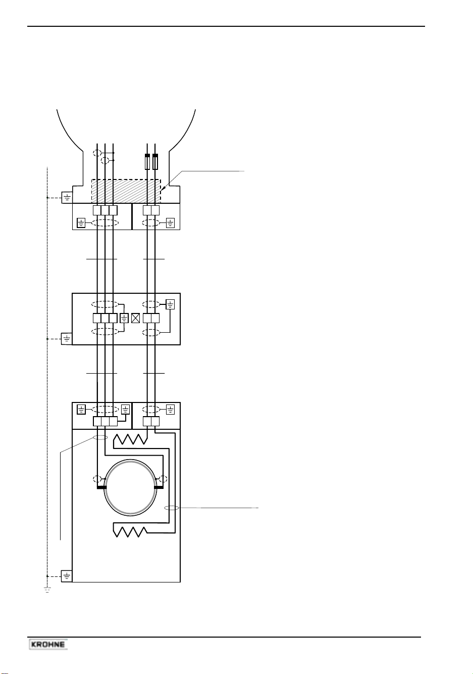
Connection diagram 2: Use of heat-resistant cables
Hazardous locations
of Zone 1 and 2
EQUIPOTENTIAL BONDING CONDUCTOR
≥
4 mm
2
(OPTIONAL)
Electrode cables - white/pink
(PTFE insulated shielded copper)
Field c oil wires - green/bl ue
(PTFE insulated copper)
Flow tube
E
IFS x000 F-EEx
Primary Head type
Coil
E
Coil
E = electrode
3 2 1 7 8
ELECTRONICS COMPARTMENT (always "EEx d")
Intrinsical safe ("ib") Increased safe ("e")
electrode circuits field coil circuits
(No. "3", "2", "1") (No. "7", "8")
Signal Converter
IFC 090 F/…-EEx
Flameproof (EEx d) cable
feed-through LC-2/EEx
BC
2x fuse
160mA
3 2 1 7 8
3 2 1 7 8
ED
ZD-EEx
intermediate
junction box
ALTOFLUX IFC 090 F-EEx and ALTOFLUX IFC 090 F / i-EEx 11
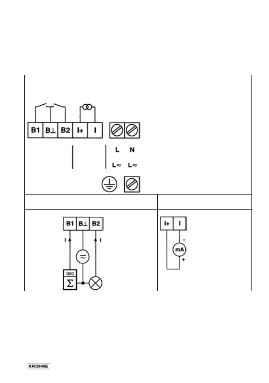
2.5 Regular IFC 090-EEx electronics unit
The field cables that enter the terminal compartment of the IFC 090-EEx signal converter unit (i.e.
power supply, current and binary outputs) are non-intrinsically safe. To connect external devices
to the signal output terminals, the wiring requirements for the type of protection of the
compartment (standard: increased safety "e", optional: flameproof "d") must be conform to the
international or national standard involved (e.g. EN 60079-14).
Terminal arrangement in terminal compartment
pulse and status outputs
or control inputs
100 - 240 V AC / 48 - 63 Hz
24 V AC / DC
PE Protective earth
FE Functional earth
Passive pulse/status output
Active current output
I ≤ 150 mA
electronic
or electro-
mechanical
totalizer
I ≤ 150 mA
U
ext
≤ 32 V DC
≤ 24 V AC
e.g.
signal
indicator
R
i
≤ 500 Ω
Note:
The binary outputs (terminals B1, B⊥ and B2) can only be configured as passive
outputs, the current output (terminals I+ and I) can only be configured as active output.
For power supply versions with the nominal voltage in the range of 100 to 230 Vac the PE
conductor must always be connected to the M5 clamp terminal marked with the safety earth
symbol that is press-fitted in the dividing aluminium wall of the signal converter housing. For the
24 Vac/dc power supply, the PE conductor may be connected, but it not required for the safety of
tthe flowmeter. The terminal arrangement is shown above.
binary
outputs
current
output
 Loading...