


www.krohne.com
7022812100
C KROHNE 03/2005
GM
Installation and
Operating Instructions
H54 / M4
Variable Area Flowmeter
For explosion protected devices please refer to Supplementary Installation an Operating Instructions:
GA24/... Cat. II2GD
Cat. II3GD without electr. built-in parts Id. No. 702271##00
Variable area flowmeters
Vortex flowmeters
Flow controllers
Electromagnetic flowmeters
Ultrasonic flowmeters
Mass flowmeters
Level measuring instruments
Communications technology
Engineering systems & solutions
Switches, counters, displays and recorders
Heat metering
Pressure and temperature

Product liability and warranty
The variable area flowmeter is suitable for measuring the volume flow of liquids, gases and vapor.
Special regulations apply for use in explosion-hazardous areas. Responsibility for the suitability and usage to the intended purpose of these flowmeters rests solely with the operator.
Improper installation or improper operation of the flowmeters may lead to the loss of warranty. In addition, the "General conditions of sale" which forms the basis of the purchase contract are applicable.
The calculation of the pressurized parts is effected with allowance for corrosion, erosion through abrasion or cavitation.
If the flowmeter needs to be returned to KROHNE Messtechnik, please note the information at the end of these installation and operating instructions.
Scope of delivery
The scope of delivery of the variable area flowmeter in the version respectively ordered includes: - Installation and operating instructions Ident. No. 702281##00
For explosion protected devices please refer to Supplem. Installation an Operating Instructions:
H54/... Cat. II2GD Cat. II3GD without electr. built-in parts Id. No. 702271##00 - Supply without installation accessories (screw bolts, flange seal and cabling)
Special certificates (supplied to order only)
-Record on setting in works
-Test certificate to EN 10204:
-Pressure test, paint penetration test, irradiation test, leak test, ultrasonic test, helium leakage test,
-Cleaning to works regulations.
2 |
H54 Installation and operating instructions |

Table of Contents |
|
|
Product liability and warranty ................................................................................................................... |
2 |
|
1 |
General................................................................................................................................................ |
4 |
1.1 |
Type code........................................................................................................................................ |
4 |
1.2 |
Marking............................................................................................................................................ |
4 |
1.3 |
Key for Pressure Equipment Directive ............................................................................................ |
5 |
1.4 |
Functional principle.......................................................................................................................... |
5 |
2 |
Installation and Start-up.................................................................................................................... |
6 |
2.1 |
Protection during shipment.............................................................................................................. |
6 |
2.2 |
Prerequisite for the installation ........................................................................................................ |
6 |
2.3 |
Preparation of the pipeline............................................................................................................... |
6 |
2.4 |
Installation in the pipeline ................................................................................................................ |
6 |
2.5 |
Fastening torque.............................................................................................................................. |
6 |
2.6 |
Magnetic filters ................................................................................................................................ |
7 |
2.7 |
Observance of the IP degree (NEMA Type) of protection............................................................... |
7 |
2.8 |
Start-up............................................................................................................................................ |
7 |
2.9 |
Measurement of liquids ................................................................................................................... |
7 |
2.10 |
Measurement of gases .................................................................................................................... |
7 |
3 |
Flow tables ......................................................................................................................................... |
8 |
4 |
Materials ............................................................................................................................................. |
9 |
5 |
Technical Data.................................................................................................................................. |
10 |
6 |
Medium Temperatures..................................................................................................................... |
10 |
7 |
Dimensions and weights................................................................................................................. |
11 |
8 |
Limit switches .................................................................................................................................. |
12 |
8.1 |
Electrical connection...................................................................................................................... |
12 |
8.2 |
Setting............................................................................................................................................ |
12 |
8.3 |
Technical data of limit switches..................................................................................................... |
12 |
9 |
Electrical signal output ESK II........................................................................................................ |
13 |
10 Electrical signal output ESK3-PA................................................................................................... |
14 |
|
11 |
Maintenance ..................................................................................................................................... |
15 |
Information on returning instruments.................................................................................................... |
15 |
|
Form for returning the instrument.......................................................................................................... |
16 |
|
3 |
H54 Installation and operating instructions |
1 General
1.1Type code
The type code consists of the following elements: 1)
H 5 4 |
/ |
|
/ |
|
|
|
/ |
|
/ |
|
1 |
|
2 |
3 |
|
4 |
5 |
6 |
|||
1Series measuring unit H54
2Materials
RR : stainless Steel
|
C |
: |
stainless steel with PTFE liner |
3 |
Heating jacket design |
||
|
B |
: |
with heating jacket |
4 |
Display part series |
||
|
M4 |
: |
mechanical indicator |
|
M10 |
: |
electronic transmitter with LC display M10 |
5 |
Signal output (M4 display) |
||
|
ESK |
: |
electronic transmitter |
6 |
Limit switch |
|
|
|
K1 |
: |
one limit switch |
|
K2 |
: |
two limit switches |
1) Positions which are not used in the type code are not required.
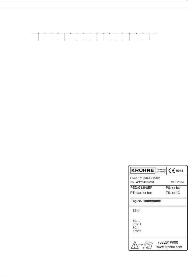
1.2Marking
The type marking of the complete instrument is carried out at the display part by means of the rating plates shown here (also refer to the type code).
|
Example: |
MD: |
Manufacturing date |
PS: |
Max. permissible operating |
|
pressure at max. permissible operating temperature TS |
PT max: |
Maximum pressure tested |
TS: |
Max. operating temperature |
PED: |
Directive for Pressure Equipment |
Tag No : |
Measuring point tag |
0044: |
Identification number of the supervising office for |
|
EC Directive for Pressure Equipment 97/23/EC |
SN: |
Serial number |
SO: |
Sales order / item |
KO: |
KROHNE order |
V251…: |
Product configurator code |
AC: |
Article code |
4 |
H54 Installation and operating instructions |
1.3Key for Pressure Equipment Directive
PED |
/ |
|
|
/ |
|
/ |
|
|
|
|
|
|
|
|
|
1 |
2 |
3 |
4 |
5 |
|||
1Pressure Equipment Directive
2Fluid
G Gases, liquefied gases, gases dissolved under pressure, vapors and those liquids whose vapor pressure lies more than 0.5 bars over the normal atmospheric pressure (1013 mbars) at the maximum permissible temperature
L Liquids whose vapor pressure lies a maximum of 0.5 bars above the atmospheric pressure at the maximum permissible temperature
3Fluid group
1 |
Group 1: |
Explosion-hazardous, highly flammable, readily flammable, flammable |
|
|
(when the maximum permissible temperature lies above the flash point), |
|
|
highly toxic, toxic, fire stimulating |
2 |
Group 2: |
All the fluids not specified in Group 1 |
4Category
3.3 In accordance with Article 3.3 of Directive 97/23/EC I Category I to 97/23/EC
II Category II to 97/23/EC III Category III to 97/23/EC
5Conformity evaluation process
SEP |
Solid engineering practice |
A |
Module A internal process inspection |
A1 |
Module A1 internal process inspection with supervision of the acceptance |
H |
Module H Comprehensive quality assurance |
The PED key marking is contained on the rating plate of the instrument.
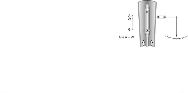
1.4Functional principle
The flowmeter operates in accordance with the float measuring principle.
A metal cone is installed in the measuring unit H54, in which a suitably formed float can move freely up and down.
The flowmeter is inserted into a vertical pipeline and the medium flows through it from bottom to top.
The guided float adjusts itself so that the buoyancy force A acting on it, the wave resistance W and its weight G are in equilibrium (G = A + W).
An annular gap which depends on the flow rate results. The height of the float in the measuring unit, which depends on the flow, is transmitted by a magnetic coupling and displayed on a scale. Strong magnetic fields can lead to deviations in the measured value.
The installation of several instruments in immediate vicinity to each other does not cause notable influences.
5 |
H54 Installation and operating instructions |
 Loading...