


 IFC 300 Supplementary instructions
Signal converter for electromagnetic flowmeters
Description of PROFIBUS interface
PROFIBUS PA:
PROFIBUS device with MBP Physical Interface and PA Profile 3.0 (V3.0.2 / 100811)
PROFIBUS DP:
PROFIBUS device with RS485 Physical Interface and PA Profile 3.0 (V3.0.2 / 100811)
© KROHNE 02/2011 - 4001086601 - AD IFC 300 PROFIBUS R01 en

|
CONTENTS |
IFC 300 |
|
|
|
||
|
|
|
|
1 |
Safety instructions |
4 |
|
|
|
|
|
|
1.1 |
Scope of the document..................................................................................................... |
4 |
|
1.2 |
Scope of delivery............................................................................................................... |
4 |
|
1.3 |
Special notes .................................................................................................................... |
4 |
2 PROFIBUS DP |
5 |
||
|
|
|
|
|
2.1 |
Software history ............................................................................................................... |
5 |
|
2.2 |
System configuration of PROFIBUS DP network............................................................. |
6 |
|
2.3 |
Electrical connection for DP signal converter................................................................. |
7 |
|
2.4 |
Technical data................................................................................................................... |
9 |
|
2.5 |
GSD files for the data transfer ....................................................................................... |
10 |
|
2.5.1 Cyclic data exchange............................................................................................................. |
10 |
|
|
2.5.2 Baud rate............................................................................................................................... |
10 |
|
|
2.5.3 Ident.-No. supported............................................................................................................. |
10 |
|
|
2.5.4 Manufacturer specific GSD files: KR024500.GSD and KR014500.GSD ................................ |
11 |
|
|
2.5.5 Differencies of the manufacturer specific GSD files: KR024500.GSD and KR014500.GSD. 13 |
||
|
2.5.6 Profile specific GSD file: PA039740.GSD .............................................................................. |
13 |
|
|
2.5.7 Using the display menu to distinguish between Rev 1 and Rev 2 ........................................ |
13 |
|
3 PROFIBUS PA |
14 |
||
|
|
|
|
|
3.1 |
Software history ............................................................................................................. |
14 |
|
3.2 |
System configuration of PROFIBUS PA network ........................................................... |
16 |
|
3.3 |
Electrical connection for PA signal converter ............................................................... |
17 |
|
3.4 |
Technical data................................................................................................................. |
18 |
|
3.5 |
GSD files for the data transfer ....................................................................................... |
19 |
|
3.5.1 Cyclic data exchange............................................................................................................. |
19 |
|
|
3.5.2 Ident.-No. supported............................................................................................................. |
19 |
|
|
3.5.3 Manufacturer specific GSD files: KR024501.GSD and YP024501.GSD................................. |
20 |
|
|
3.5.4 Profile specific GSD file: PA139740.GSD .............................................................................. |
22 |
|
|
3.5.5 Using the display menu to distinguish the current revision of the device (PA) ................... |
23 |
|
|
3.6 |
Signal converter IFC 300 PROFIBUS PA with MBP interface as replacement for older |
|
|
signal converter IFC 090 PA.................................................................................................. |
23 |
|
|
3.6.1 Ident.-No. supported............................................................................................................. |
23 |
|
|
3.6.2 Manufacturer specific GSD files (PA): KROHF401.GSD and YP01F401.GSD for the older sig- |
||
|
nal converter IFC090 with PROFIBUS MBP interface.................................................................... |
23 |
|
4 |
Application profile |
25 |
|
|
|
|
|
|
4.1 |
Function blocks .............................................................................................................. |
25 |
|
4.2 |
Data structure of function block output values ............................................................. |
25 |
|
4.2.1 Float value............................................................................................................................. |
25 |
|
|
4.2.2 Status value........................................................................................................................... |
26 |
|
|
4.3 |
Diagnosis parameter ...................................................................................................... |
28 |
|
4.3.1 Diagnosis............................................................................................................................... |
28 |
|
|
4.3.2 DIAGNOSIS (if "Classic Status" and "Diagnosis" selected).................................................. |
28 |
|
|
4.3.3 DIAGNOSIS_EXTENSION (if "Classic Status" and "Diagnosis" selected) ............................ |
30 |
|
|
4.3.4 Mapping of DIAGNOSIS_EXTENSION bits into DIAGNOSIS bits........................................... |
31 |
|
2 |
www.krohne.com |
02/2011 - 4001086601 - AD IFC 300 PROFIBUS R01 en |

|
|
|
|
CONTENTS |
|
|
|
|
IFC 300 |
|
|
||||
|
|
|
|
|
|
||
5 |
Profibus settings |
34 |
|
||||
|
|
|
|
|
|
|
|
|
|
|
5.1 |
Menu A, quick setup ....................................................................................................... |
34 |
||
|
|
|
5.2 |
Menu B, test.................................................................................................................... |
34 |
||
|
|
|
5.3 |
Menu C, setup................................................................................................................. |
35 |
||
|
|
|
5.4 |
Menu D, service .............................................................................................................. |
38 |
||
6 |
Notes |
|
39 |
|
|||
|
|
|
|
|
|
|
|
02/2011 - 4001086601 - AD IFC 300 PROFIBUS R01 en |
www.krohne.com |
3 |

1 SAFETY INSTRUCTIONS |
|
|
IFC 300 |
|
|
|
|
|
1.1 Scope of the document
These instructions are supplementary to the signal converter Handbook. For all other data, use the relevant chapters of the Handbook. If you do not have this document, please contact the nearest office or download them from the manufacturer's internet site.
INFORMATION!
The information in this chapter only contains the data applicable to PROFIBUS communication. The technical data in the Handbook shall be valid in its current version, provided that it is not rendered invalid or replaced by this supplement.
1.2 Scope of delivery
The information in this chapter only contains the data applicable to PROFIBUS communication. The technical data in the Handbook shall be valid in its current version, provided that it is not rendered invalid or replaced by this supplement.
A device for PROFIBUS communication is supplied with:
•Supplementary instructions for PROFIBUS communication
•PROFIBUS device data files (GSD) on a CD-ROM supplied with the device
1.3Special notes
Don't switch off (power off) the signal converter immediately after manual change of parameter values:
•Please wait approx. 10 seconds before you switch off the signal converter after you have done both a parameter download via PROFIBUS or a manual change of a parameter value via the local display.
•Please wait approx. 15 seconds before you switch off the signal converter after you have carried out a "Factory Reset" (PROFIBUS "Coldstart") via PROFIBUS or local display.
"Deactivation of the Service Parameter Lock" of the signal converter via PROFIBUS:
•After writing down the service password (via PROFIBUS) the "Deactivation of the Service Parameter Lock" will last at least 10 minutes if the internal password timer of the signal converter won't be retriggered by writing this password again. The "Deactivation of the Service Parameter Lock" will be terminated at once by a PROFIBUS Coldstart / Warmstart or if the internal password timer of the signal converter elapsed.
4 |
www.krohne.com |
02/2011 - 4001086601 - AD IFC 300 PROFIBUS R01 en |

|
|
|
|
|
|
|
|
|
PROFIBUS DP 2 |
|
|
IFC 300 |
|
|
|
|
|
|
|||
|
2.1 Software history |
|
|
|
|
|
|
|||
|
|
|
|
|
|
|
||||
|
|
|
|
|
|
|
|
|
|
|
|
Issued |
|
Signal converter |
Application program |
System integration |
|
||||
|
|
|
|
|
|
|
|
|
|
|
|
Mth./ |
|
Hardware |
Firmware |
Hardware |
Software |
Driver |
Version |
Model name |
|
|
year |
|
|
|
|
|
|
|
|
|
|
|
|
|
|
|
|
|
|
|
|
|
04/05 |
|
Signal |
V1.1.3 / 050413 |
Simatic |
HW Config |
GSD |
KR014500.GSD |
IFC300(RS485) |
|
|
09/05 |
|
converter |
V1.2.0 / 060215 |
PCS7 |
|
manuf. |
|
|
Rev.1 |
|
|
|
with |
|
|
other |
specific |
|
|
|
|
|
|
RS485 |
|
other SPS |
Software of |
|
|
|
|
|
|
|
|
GSD |
PA039740.GSD |
Flow with 1AI, |
||||
|
|
|
interface + |
|
of other |
other SPS |
||||
|
|
|
|
profile |
|
|
1TOT (PhyL 0) |
|||
|
|
|
PA Profile |
|
manufact. |
manufact. |
|
|
||
|
|
|
|
specific |
|
|
|
|||
|
|
|
3.0 |
|
|
|
|
|
|
|
|
|
|
(special) |
|
Laptop |
- |
DD |
- |
|
- |
|
|
|
|
|
|
|
(Ident.-No.) |
|
|
|
|
|
|
|
|
|
- |
DTM ≥ |
- |
|
- |
|
|
|
|
|
|
|
|
|
|
|
|
01/06 |
|
Signal |
V2.0.0 / 060112 |
Simatic |
HW Config |
GSD |
KR014500.GSD* |
IFC300(RS485) |
|
|
|
|
converter |
V2.0.0 / 060126 |
PCS7 |
|
manuf. |
KR024500.GSD |
Rev.1 |
|
|
|
|
with |
|
|
other |
specific |
|
|
IFC300(RS485) |
|
|
|
RS485 |
|
other SPS |
Software of |
|
|
|
Rev.2 |
|
|
|
interface + |
|
of other |
other SPS |
|
|
|
|
|
|
|
|
GSD |
PA039740.GSD |
Flow with 1AI, |
||||
|
|
|
PA Profile |
|
manufact. |
manufact. |
||||
|
|
|
|
profile |
|
|
1TOT (PhyL 0) |
|||
|
|
|
3.0 |
|
|
|
|
|
||
|
|
|
|
|
|
specific |
|
|
|
|
|
|
|
(special) |
|
|
|
|
|
|
|
|
|
|
|
|
|
|
|
|
|
|
|
|
|
|
|
Laptop / PC |
PDM |
DD |
I3P*DD0300.03** |
- |
|
|
|
|
|
|
|
(≥ 6.0 SP3) |
(Ident.-No.) |
|
|
|
|
|
|
|
|
|
|
|
|
|
|
|
|
|
|
|
|
Pactware |
DTM ≥ |
GFP*DTM1.3.1 |
- |
|
|
|
|
|
|
|
|
|
FDT1.2 |
|
|
|
|
|
|
|
|
|
|
|
|
|
|
04/08 |
|
Signal |
V3.0.2 / 080422 |
Simatic |
HW Config |
GSD |
KR014500.GSD* |
IFC300(RS485) |
|
|
|
|
converter |
|
PCS7 |
|
manuf. |
KR024500.GSD |
Rev.1 |
|
|
|
|
with |
|
|
other |
specific |
|
|
IFC300(RS485) |
|
|
|
RS485 |
|
other SPS |
Software of |
|
|
|
Rev.2 |
|
|
|
interface + |
|
of other |
other SPS |
|
|
|
|
|
|
|
|
GSD |
PA039740.GSD |
Flow with 1AI, |
||||
|
|
|
PA Profile |
|
manufact. |
manufact. |
||||
|
|
|
|
profile |
|
|
1TOT (PhyL 0) |
|||
|
|
|
3.0 |
|
|
|
|
|
||
|
|
|
|
|
|
specific |
|
|
|
|
|
|
|
|
|
|
|
|
|
|
|
|
|
|
|
|
|
|
|
|
|
|
|
|
|
|
|
Laptop / PC |
PDM |
DD |
I3P*DD0300.03** |
- |
|
|
|
|
|
|
|
(≥ 6.0 SP3) |
(Ident.-No.) |
|
|
|
|
|
|
|
|
|
|
|
|
|
|
|
|
|
|
|
|
Pactware |
DTM ≥ |
GFP*DTM1.3.1 |
- |
|
|
|
|
|
|
|
|
|
FDT1.2 |
|
|
|
|
|
|
|
|
|
|
|
|
|
02/2011 - 4001086601 - AD IFC 300 PROFIBUS R01 en |
www.krohne.com |
5 |
2 PROFIBUS DP |
IFC 300 |
|
Issued |
Signal converter |
Application program |
System integration |
|
|||
|
|
|
|
|
|
|
|
Mth./ |
Hardware |
Firmware |
Hardware |
Software |
Driver |
Version |
Model name |
year |
|
|
|
|
|
|
|
|
|
|
|
|
|
|
|
01/11 |
Signal |
V3.0.2 / 100811 |
Simatic |
HW Config |
GSD |
KR014500.GSD* |
IFC300(RS485) |
|
converter |
|
PCS7 |
|
manuf. |
KR024500.GSD |
Rev.1 |
|
with |
|
|
other |
specific |
|
IFC300(RS485) |
|
RS485 |
|
other SPS |
Software of |
|
|
Rev.2 |
|
interface + |
|
of other |
other SPS |
|
|
|
|
|
GSD |
PA039740.GSD |
Flow with 1AI, |
|||
|
PA Profile |
|
manufact. |
manufact. |
|||
|
|
profile |
|
1TOT (PhyL 0) |
|||
|
3.0 |
|
|
|
|
||
|
|
|
|
specific |
|
|
|
|
|
|
|
|
|
|
|
|
|
|
|
|
|
|
|
|
|
|
Laptop / PC |
PDM |
DD |
I3P*DD0300.03** |
- |
|
|
|
|
(≥ 6.0 SP3) |
(Ident.-No.) |
|
|
|
|
|
|
|
|
|
|
|
|
|
|
Pactware |
DTM ≥ |
GFP*DTM1.3.1 |
- |
|
|
|
|
|
|
FDT1.2 |
|
|
|
|
|
|
|
|
|
|
|
|
|
|
|
I3P*DTM1.0.7 |
- |
|
|
|
|
|
|
FDT1.2 |
|
|
|
|
|
|
|
|
|
*: If the GSD file "KR014500.GSD" is used, there will be supported only a limited amount of functions by the software version (V1.2.0 / 060215 or V2.0.0 / 060112): I&M functions and fail safe mode are not accessible. For full support of all profile specific or manufacturer specific functions/parameters use the GSD file "KR024500.GSD".
GFP*: Generic Flow PROFIBUS I3P*: IFC300 PROFIBUS
**: PDM 5.2 PDM 6.0
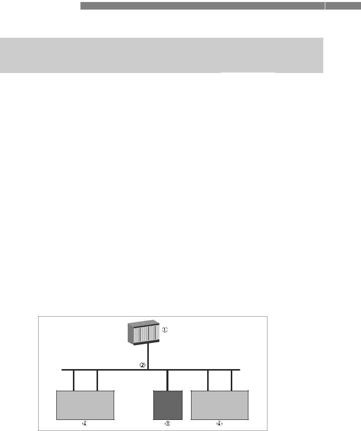
2.2 System configuration of PROFIBUS DP network
The following diagram shows a typical network configuration with PROFIBUS devices with RS485 interface in a non-hazardous environment. The PROFIBUS devices with RS485 interface do not need any segment coupler. They are connected directly to the PROFIBUS DP network.
Figure 2-1: PROFIBUS DP network
1SPS
2PROFIBUS DP with max. 12 Mbit/s
3Signal converter
4Other devices with PROFIBUS RS485 interface
6 |
www.krohne.com |
02/2011 - 4001086601 - AD IFC 300 PROFIBUS R01 en |
|
|
PROFIBUS DP 2 |
|
IFC 300 |
|
|
|
|
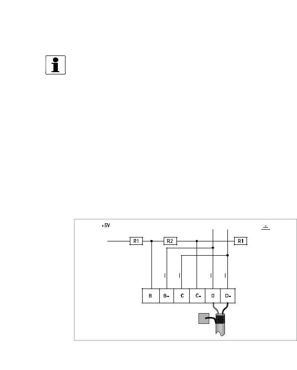
2.3 Electrical connection for DP signal converter
INFORMATION!
For a detailed description of the electrical connections please refer to the standard signal converter handbook.
Signal converter terminals |
B |
B- |
C |
C- |
D |
D- |
|
|
|
|
|
|
|
PROFIBUS designation |
T |
+B |
-A |
-T |
+B |
-A |
|
|
|
|
|
|
|
|
1 |
2 |
3 |
4 |
5 |
6 |
|
|
|
|
|
|
|
1Termination positive
2TxD+/RxD+ second connection
3TxD-/RxD- second connection
4Termination negative
5TxD+/RxD+ first connection
6TxD-/RxD- first connection
External connection with spur
CAUTION! |
Spurs are not allowed at high data rates!
I = 110 nH
R1 = 390 Ω
R2 = 220 Ω
02/2011 - 4001086601 - AD IFC 300 PROFIBUS R01 en |
www.krohne.com |
7 |
2 PROFIBUS DP |
IFC 300 |
|
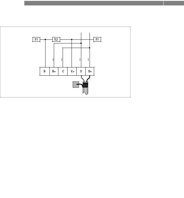
External connection at last device with active internal bus termination
I = 110 nH |
R1 = 390 Ω |
R2 = 220 Ω |
External connection to a trunk
1e.g. incoming data lines
2e.g. outgoing data lines
I = 110 nH
R1 = 390 Ω
R2 = 220 Ω
8 |
www.krohne.com |
02/2011 - 4001086601 - AD IFC 300 PROFIBUS R01 en |

|
|
|
|
PROFIBUS DP 2 |
|
IFC 300 |
|
||
|
2.4 Technical data |
|
|
|
|
|
|
||
|
|
Hardware |
|
|
|
|
|
|
|
|
|
Type |
PROFIBUS RS485 interface according to IEC 61158-2 |
|
|
|
|
|
|
|
|
Connection |
Dependent of polarity; please note at electrical connection! |
|
|
|
Software |
|
|
|
|
|
|
|
|
|
GSD |
GSD file on CD-ROM or from internet site |
|
|
|
|
|
|
|
|
Device profile |
PA Profile compact class B, V 3.0 |
|
|
|
|
|
|
|
|
Address range |
0…126 (default 126) |
|
|
|
|
0…125 via PROFIBUS service set_slave_add |
|
|
|
|
0…126 via local display |
|
|
|
|
126 via factory_reset = 2712 |
|
|
|
|
|
|
|
|
Local control |
Local display and operator interface at device |
|
|
|
|
|
|
|
|
SAPs |
2 x MS1 SAPs – acyclic interface to PLC |
|
|
|
|
|
|
|
|
|
3 x MS2 SAPs – the number of MS2 Service Access Points is typically |
|
|
|
|
equal to the maximum number of master class 2 tools |
|
|
|
Function blocks |
1 x TB = Transducer Block: contains the parameters and functions |
|
|
|
|
defined in PA Profile 3.0 |
|
|
|
|
|
|
|
|
|
1 x PB = Physical Block: contains the parameters defined in PA |
|
|
|
|
Profile 3.0 |
|
|
|
|
|
|
|
|
|
5 x AI = Analog Input Blocks: contains the parameters defined in PA |
|
|
|
|
Profile 3.0 |
|
|
|
|
|
|
|
|
|
3 x TOT = Totalizer Function Blocks: contains the parameters defined |
|
|
|
|
in PA Profile 3.0 |
|
|
|
|
|
|
02/2011 - 4001086601 - AD IFC 300 PROFIBUS R01 en |
www.krohne.com |
9 |

2 PROFIBUS DP |
IFC 300 |
|
2.5 GSD files for the data transfer
A PROFIBUS GSD ZIP file (e.g. GSD-31777813.zip; including both all GSD files and additional data files) you can get on a CD ROM or can be downloaded from the internet. The GSD file contains information that will be needed for project planning of the PROFIBUS communication network.
The relevant data files (e.g. _ _ _ _ .bmp / _ _ _ _ .dib) must be loaded into the bus configuration system/master system before start-up of the bus system.
2.5.1 Cyclic data exchange
During network configuration the user has to define which function block outputs of the signal converter should be transferred cyclically to the master. Network configuration will be done using one of the GSD files described before. The order of transmission of a function block always remains the same even if a function block is defined as an "Empty" block (if so, no function block output data will be sent to the master and all function block outputs following the empty block will move up one position).
2.5.2 Baud rate
Supported baud rates are listed in the GSD file (see below). After power-on or PROFIBUS timeout a baud rate search is active to detect the current transfer speed on the bus. It is not necessary to set the baud rate manually.
If the data transmission rate is changed during operation the baud rate search will not be started by the device. A new power-up or a manual interruption of the PROFIBUS communication is required to activate the baud rate search in this case.
2.5.3 Ident.-No. supported
The signal converter with PROFIBUS RS485 interface is based on PROFIBUS PA Profile V 3.0. The device supports two Ident-No.:
•Ident-No. "4500hex" belongs to the GSD file KR014500.GSD and KR024500.GSD and includes the complete functionality of the electromagnetic flowmeter.
•The application of the manufacturer independent Ident-No. "9740hex" (GSD file "PA039740.GSD") provides interchangeability of devices, i.e. an exchange of electromagnetic flowmeters of different vendors.
Please follow the instructions in the manual of the host supplier when installing the GSD File you need and the additional files (_ _ _ _ .bmp and _ _ _ _ .dib) into the PLC.
INFORMATION!
If separated by the bus configuration system the device entry of the PROFIBUS RS485 interface with PA Profile 3.0 will be located within the slave family PROFIBUS PA.
10 |
www.krohne.com |
02/2011 - 4001086601 - AD IFC 300 PROFIBUS R01 en |
|
|
PROFIBUS DP 2 |
|
IFC 300 |
|
|
|
|
2.5.4 Manufacturer specific GSD files: KR024500.GSD and KR014500.GSD
The manufacturer delivers the GSD files with the entire device functionality, which is listed as follows:
Block |
Default configuration |
KR024500.GSD |
Default |
number |
Function block output: value and |
KR014500.GSD |
unit |
|
status |
Ident-No. 4500 |
|
|
|
|
|
1 |
Volume Flow |
AI-FB |
m3/h |
2 |
Volume Totalizer |
Totalizer-FB |
m3 |
3 |
Volume Totalizer |
Totalizer-FB |
m3 |
4 |
Mass Totalizer |
Totalizer-FB |
kg |
|
|
|
|
5 |
Mass Flow |
AI-FB |
kg/s |
|
|
|
|
6 |
Speed Flow |
AI-FB |
m/s |
|
|
|
|
7 |
Coil Temperature |
AI-FB |
K |
|
|
|
|
8 |
Conductivity |
AI-FB |
S/m |
|
|
|
|
X |
Electronic Temperature |
AI-FB |
°C |
|
|
|
|
X |
Supply |
AI-FB |
V |
|
(internal supply voltage for the |
|
|
|
PROFIBUS interface) |
|
|
|
|
|
|
•AI: Analog Input Function Block
•FB: Function Block
•X: Block number 1, 5, 6, 7 or 8
There will be two additional output values available by changing the function block channel parameters of the above mentioned "Analog Input Function Blocks".
There are separate settings to select the units for local display and PROFIBUS. Modifications of the units of the display will have no effect on the data transferred via PROFIBUS.
A master class 2 tool is required to modify the units for PROFIBUS transfer.
INFORMATION!
During network configuration the user has to define which function block outputs of the signal converter should be transferred cyclically to the master. This is performed by a bus configuration tool (e.g. "HWConfig" for PC-S7 from Siemens). This tool offers specific functions as follows:
1.It is possible to configure an "Empty" block (the code of an "Empty" block is defined as 0x00) on each block number. This implies: no data are transmitted in the cyclic data telegram for this block.
2.There is NO "Totalizer (TOT)" function block allowed on block position 1, 5, 6, 7 and 8! On these positions, only an "Analog Input (AI)" function block or an "Empty" block is allowed!
(Note: All codes supported by "Analog Input (AI)" - and "Totalizer (TOT)" – function blocks will be found in the corresponding GSD files.)
3.There is NO "Analog Input (AI)" function block allowed on block position 2, 3 and 4! On these positions, only a "Totalizer (TOT)" function block or an "Empty" block is allowed!
4.There is a choice of 7 different totalizer functions, which can be allocated to the blocks 2, 3 and/or 4.
02/2011 - 4001086601 - AD IFC 300 PROFIBUS R01 en |
www.krohne.com |
11 |

2 PROFIBUS DP |
IFC 300 |
|
Definition of totalizer functions
Total |
cyclic transfer of the totalizer value with status to the master |
|
|
SetTot + Total |
cyclic transfer of the totalizer value with status to the master + cyclic |
|
control data from master to the device via the parameter SetTot |
ModeTot + Total |
cyclic transfer of the totalizer value with status to the master + cyclic |
|
control data from master to the device via the parameter ModeTot |
|
|
SetTot + ModeTot + Total |
cyclic transfer of the totalizer value with status to the master + cyclic |
|
control data from master to the device via the parameters SetTot and |
|
ModeTot (in the given order) |
|
|
SetTot |
cyclic control data from master to the device via the parameter |
|
SetTot |
|
|
ModeTot |
cyclic control data from master to the device via the parameter |
|
ModeTot |
|
|
SetTot + ModeTot |
cyclic control data from master to the device via the parameters |
|
SetTot and ModeTot (in the given order) |
|
|
Both, the Byte SetTot and ModeTot are cyclically sent from the master to the device if these bytes are inserted as output data via the PLC configurator. The meaning of these control bytes are as follows:
Function of control bytes
SetTot
SetTot = 0 |
Totalizer is totalizing. |
|
|
SetTot = 1 |
Totalizer will be reset to 0 and stays at 0 until SetTot is switched back |
|
again to 0. If the value of SetTot changes from "1" to "0" the totalizer |
|
starts counting from 0. |
|
|
SetTot = 2 |
Totalizer is set to the value defined by PresetTot. PresetTot can be |
|
written via an acyclic master (totalizer in block 2 = Slot 2 Index 32; |
|
totalizer in block 3 = Slot 3 Index 32; totalizer in block 4 = Slot 4 Index |
|
32). If the value of SetTot changes from "2" to "0" the totalizer starts |
|
counting from the current value defined by PresetTot. |
|
|
SetTot > 2 |
Not allowed. Value is ignored; totalizer remains in its last valid |
|
setting. |
|
|
ModeTot |
|
|
|
ModeTot = 0 |
Totalizer totalizes positive and negative values. |
|
|
ModeTot = 1 |
Totalizes only positive values. |
|
|
ModeTot = 2 |
Totalizes only negative values. |
|
|
ModeTot = 3 |
Totalizer is stopped, no totalization will be done. |
|
|
ModeTot = 248 |
Totalizes all values as positive, negative values will be multiplied with |
|
-1.0. |
|
|
ModeTot = 249 |
Totalizes all values as negative, positive values will be multiplied with |
|
-1.0. |
|
|
All other values of ModeTot not allowed. Value is ignored; totalizer remains in its last valid setting.
The standard block configuration may be changed by the customer but using the default settings is highly recommended. If the standard block configuration should be changed by the customer an acyclic master tool or the device display menu must be used to change the "channel parameter" value of the block which should be connected to another transducer output value.
12 |
www.krohne.com |
02/2011 - 4001086601 - AD IFC 300 PROFIBUS R01 en |
 Loading...