


03/12
Electromagnetic
Flow Switch and Flow Meter
Installation and
Operating
Instructions
DWM 1000
DWM 2000
DWM 2000 L DWM 2000 IP68
KROHNE S.A. CERTIFIED ISO 9001

Contents |
|
|
Page |
Introduction..................................................... |
3 |
Special Features |
|
Measuring Principles |
|
Components |
|
Installation....................................................... |
4 |
Mounting on Pipeline |
|
Dimensions and Weight |
|
Electrical Connection and Settings |
|
DWM1000................................................ |
5 |
DWM2000................................................ |
6 |
Compatible Relays (for DWM1000)........... |
7 |
Version DWM2000 IP68............................. |
8 |
Version DWM2000 Long |
|
Characteristics ........................................ |
8 |
Components............................................ |
8 |
Installation................................................ |
9 |
Trouble Shooting............................................ |
10 |
Technical Data................................................ |
11 |
KROHNE Contact Addresses..................... |
12 |
2
DWM Flow Meters and Switches
The DWM electromagnetic flow meters and switches are designed to measure and monitor the flow rates of
e l e c t r i c a l l y c o n d u c t i v e l i q u i d s , p a s t e s a n d s l u r r i e s
Versions
DWM 1000 flow switch, 2-wire system.
DWM 2000 flow meter, 4-20 mA current output/readout.
DWM 2000 L (Long) for flow pipes of greater than 400m diameter or open channels.
DWM 2000 IP68 for immersed applications.
DWM 2000 FT for food applications with Tuchenhagen connection (detailed in a separate instructions leaflet).
Special Features
Rugged design, IP55 protection, equivalent to NEMA 4 and 4X standards.
All wetted surfaces of ceramic, stainless steel and platinum.
Compatible with process temperatures up to 150°C (300°F), and ambient temperatures between - 25 à + 60°C
Suitable for operating pressures up to 25 bar (360psi).
No moving parts, maintenance free.
Electronic unit replaceable without interruption of flow.
Compatible for all pipelines with nominal diameter (DN) 50mm (2”).
Readout connection possible with handheld consoles (DWM 2000 only).
Measuring Principle
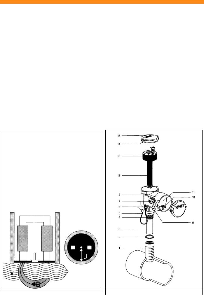
If an electrical conductor moves through a magnetic field, a voltage,U, is induced in the conductor. In the case of the DWM, the liquid in the flow pipe is the electrical conductor. In the diagram below, the DWM creates the magnetic field, B, perpendicular to the direction of flow. The induced voltage U is directly proportional to the local flow velocity v.
U = k x B x v x D k - Instrument constant
B - Strength of magnetic field v - Flow velocity
D - Electrode spacing
Voltage U is tapped off from the electrodes, neutral and ground electrode (connection socket)
DWM 1000 Flow Switch - Voltage U is converted into a switching signal with adjustable switching point.
DWM 2000 Flow Meter - Voltage U is converted into a flowproportional output signal current between 4-20 mA (load independant).
Components of DWM 1000/2000
1 Connection Socket
2Gasket
3Sensor
4Threaded Connection (1")
5Earthing Cable
6Earth Clamping Strap
7Cable Entry Gland M20x1.5
8Housing
9Blanking Plug
10Supply Terminals
11Connection Chamber
12Magnetic Coils and Electrode Contacts
13Electronic Unit
14Cover Screws
15Cover With Fitted Gasket
3

Installation
Mounting onto the pipeline
The DWM should be mounted onto the pipeline (nominal diameter (DN) 50mm (2") by means of the connection socket provided.
Refer to the diagrams below for the orientation and positioning of the connection socket. The socket should be inserted as
|
far as the corresponding p i p e l i n e diameter (DN) marking. In case there is pipe insulation, it is necessary to calculate the |
|
depth of insertion so that the protrusion of the probe is 1/8 of the true internal diameter (i.e. not the DN). |
|
The location hole in the pipeline should be drilled to a diameter of 39 mm (1.54") with a maximum of 0.5 mm play between |
|
the socket and bore. Secure the socket perpendicular to the pipe with four spot welds, then carry out an unbroken weld of the |
|
entire diameter, with an electrode of 1.2mm diameter and setting of 90 to 150A. |
The straight line flow distance required between the DWM and an upstream flow disturbance (inlet, pump, elbow etc) is advised to be 10 x DN and 5 x DN from downstream disturbances.
|
The DWM must be installed into the socket using the supplied gasket, which ensures water tightness and flush positioning of |
|
the ceramic probe head. Teflon tape should not be used on the thread as this insulates the required earthing contact, and |
|
prevents from correct protrusion of the probe. |
Only the electronics unit must be rotated according to the flow direction (see “Electrical Connection and Setting”).
Installation on plastic p ipes
In the case where the unit is to be installed on a plastic flow pipe, it is necessary to assure an earth connection. In all cases consult KROHNE to ensure an effective solution.
|
|
|
|
Correct |
|
Welding |
|
||
|
|
|
|
|
|
Socket |
|
|
|
|
|
|
|
|
|
|
|
|
|
Incorrect
Dimensions and Weight
Diecast aluminium housing - weight excluding socket approx. 1.85Kg (4.08lbs)
DWM1000
DWM2000
4
 Loading...