


|
|
|
|
|
|
|
|
|
|
|
|
|
|
|
|
|
|
|
|
|
|
|
|
|
|
|
|
|
|
|
|
|
|
|
|
|
|
|
|
|
|
|
|
|
|
|
|
|
|
|
|
|
|
|
|
|
|
|
|
|
|
|
|
|
|
|
|
|
|
|
|
|
|
|
|
|
|
|
|
|
|
|
|
|
|
|
|
|
|
|
|
|
|
|
|
|
|
|
|
|
|
|
|
|
|
|
|
|
|
|
|
|
|
|
|
|
|
|
|
|
|
|
|
|
|
|
|
|
|
|
|
|
|
|
|
|
|
|
|
|
|
|
|
|
|
|
|
|
|
|
|
|
|
|
|
|
|
|
|
|
|
|
|
|
|
|
|
|
|
|
|
|
|
|
|
|
|
|
|
|
|
|
|
|
|
|
|
|
|
|
|
|
|
|
|
|
|
|
|
|
|
|
|
|
|
|
|
|
|
|
|
|
|
|
|
|
|
|
|
|
|
|
|
|
|
|
|
|
|
|
|
|
|
|
|
|
|
|
|
|
|
|
|
|
|
|
|
|
|
|
|
|
|
|
|
|
|
|
|
|
|
|
|
|
|
|
|
|
|
|
|
|
|
|
|
|
|
|
|
|
|
|
|
|
|
|
|
|
|
|
|
|
|
|
|
|
|
|
|
|
|
|
|
|
|
|
|
|
|
|
|
|
|
|
|
|
|
|
|
|
|
|
|
|
|
|
|
|
|
|
|
|
|
|
|
Australia |
|
|
France |
Norway |
|||||||||||||||||||||||
KROHNE Australia Pty Ltd. |
|
|
KROHNE S.A.S. |
Krohne Instrumentation A.S. |
|||||||||||||||||||||||
Unit 19 No. 9, Hudson Ave. |
|
|
Usine des Ors |
Ekholtveien 114 |
|||||||||||||||||||||||
Castle Hill 2154, NSW |
|
|
BP 98 |
NO-1526 Moss |
|||||||||||||||||||||||
TEL.: +61(0)2-98948711 |
|
|
F-26 103 Romans Cedex |
P.O. Box 2178, NO-1521 Moss |
|||||||||||||||||||||||
FAX: +61(0)2-98994855 |
|
|
TEL.: +33(0)4-75 05 44 00 |
TEL.: +47(0)69-264860 |
|||||||||||||||||||||||
e-mail: krohne@krohne.com.au |
|
|
FAX: +33(0)4-75 05 00 48 |
FAX: +47(0)69-267333 |
|||||||||||||||||||||||
|
|
|
|
|
|
|
|
e-mail: info@krohne.fr |
e-mail: postmaster@krohne.no |
||||||||||||||||||
Austria |
|
|
|
|
|
|
|
|
|
|
|
|
|
|
|
Internet: www.krohne.no |
|||||||||||
KROHNE Austria Ges.m.b.H. |
|
|
Germany |
|
|
|
|
|
|
|
|||||||||||||||||
Modecenterstraße 14 |
|
|
KROHNE Messtechnik |
South Africa |
|||||||||||||||||||||||
A-1030 Wien |
|
|
GmbH & Co. KG |
KROHNE Pty. Ltd. |
|||||||||||||||||||||||
TEL.: +43(0)1/203 45 32 |
|
|
Ludwig-Krohne-Straße |
163 New Road |
|||||||||||||||||||||||
FAX: +43(0)1/203 47 78 |
|
|
D-47058 Duisburg |
Halfway House Ext. 13 |
|||||||||||||||||||||||
e-mail: info@krohne.at |
|
|
TEL.: +49(0)203-301- 0 |
Midrand |
|||||||||||||||||||||||
|
|
|
|
|
|
|
|
FAX: +49(0)203-301 389 |
TEL.: +27(0)11-315-2685 |
||||||||||||||||||
Belgium |
|
|
e-mail: krohne@krohne.de |
FAX: +27(0)11-805-0531 |
|||||||||||||||||||||||
KROHNE Belgium N.V. |
|
|
|
|
|
|
|
|
|
|
|
|
|
|
|
e-mail: midrand@krohne.co.za |
|||||||||||
Brusselstraat 320 |
|
|
India |
|
|
|
|
|
|
|
|||||||||||||||||
B-1702 Groot Bijgaarden |
|
|
KROHNE Marshall Ltd. |
Spain |
|||||||||||||||||||||||
TEL.: +32(0)2-4 66 00 10 |
|
|
A-34/35, M.I.D.C. |
I.I. KROHNE Iberia, S.r.L. |
|||||||||||||||||||||||
FAX: +32(0)2-4 66 08 00 |
|
|
Industrial Area, H-Block, |
Poligono Industrial Nilo |
|||||||||||||||||||||||
e-mail: krohne@krohne.be |
|
|
Pimpri Poona 411018 |
Calle Brasil, n°. 5 |
|||||||||||||||||||||||
|
|
|
|
|
|
|
|
TEL.: +91(0)20 -744 20 20 |
E-28806 Alcalá de Henares -Madrid |
||||||||||||||||||
Brazil |
|
|
FAX: +91(0)20 -744 20 40 |
TEL.: +34(0)91-8 83 21 52 |
|||||||||||||||||||||||
KROHNE Conaut |
|
|
e-mail: pcu@vsnl.net |
FAX: +34(0)91-8 83 48 54 |
|||||||||||||||||||||||
Controles Automaticos Ltda. |
|
|
|
|
|
|
|
|
|
|
|
|
|
|
|
e-mail: krohne@krohne.es |
|||||||||||
Estrada Das Águas Espraiadas, 230 C.P. 56 |
|
|
Italy |
|
|
|
|
|
|
|
|||||||||||||||||
06835 - 080 EMBU - SP |
|
|
KROHNE Italia Srl. |
Switzerland |
|||||||||||||||||||||||
TEL.: +55(0)11-4785-2700 |
|
|
Via V. Monti 75 |
KROHNE AG |
|||||||||||||||||||||||
FAX: +55(0)11-4785-2768 |
|
|
I-20145 Milano |
Uferstr. 90 |
|||||||||||||||||||||||
e-mail: conaut@conaut.com.br |
|
|
TEL.: +39(0)2-4 30 06 61 |
CH-4019 Basel |
|||||||||||||||||||||||
|
|
|
|
|
|
|
|
FAX: +39(0)2-43 00 66 66 |
TEL.: +41(0)61-638 30 30 |
||||||||||||||||||
China |
|
|
e-mail: krohne@krohne.it |
FAX: +41(0)61-638 30 40 |
|||||||||||||||||||||||
KROHNE Measurement Instruments Co. Ltd. |
|
|
|
|
|
|
|
|
|
|
|
|
|
|
|
e-mail: info@krohne.ch |
|||||||||||
Room 7E, Yi Dian Mansion |
|
|
Korea |
|
|
|
|
|
|
|
|||||||||||||||||
746 Zhao Jia Bang Road |
|
|
Hankuk KROHNE |
United Kingdom |
|||||||||||||||||||||||
Shanghai 200030 |
|
|
2 F, 599-1 |
KROHNE Ltd. |
|||||||||||||||||||||||
TEL.: +86(0)21-64677163 |
|
|
Banghwa-2-Dong |
Rutherford Drive |
|||||||||||||||||||||||
FAX: +86(0)21-64677166 |
|
|
Kangseo-Ku |
Park Farm Industrial Estate |
|||||||||||||||||||||||
Cellphone: +86(0)139 1885890 |
|
|
Seoul |
Wellingborough, |
|||||||||||||||||||||||
e-mail: info@krohne-asia.com |
|
|
TEL.: +82(0)2665-85 23-4 |
Northants NN8 6AE, UK |
|||||||||||||||||||||||
|
|
|
|
|
|
|
|
FAX: +82(0)2665-85 25 |
TEL.: +44(0)19 33-408 500 |
||||||||||||||||||
CIS |
|
|
e-mail: flowtech@unitel.co.kr |
FAX: +44(0)19 33-408 501 |
|||||||||||||||||||||||
Kanex KROHNE Engineering AG |
|
|
|
|
|
|
|
|
|
|
|
|
|
|
|
e-mail: info@krohne.co.uk |
|||||||||||
Business-Centre Planeta, Office 403 |
|
|
Netherlands |
|
|
|
|
|
|
|
|||||||||||||||||
ul. Marxistskaja 3 |
|
|
KROHNE Altometer |
USA |
|||||||||||||||||||||||
109147 Moscow/Russia |
|
|
Kerkeplaat 12 |
KROHNE Inc. |
|||||||||||||||||||||||
TEL.: +7(0)095-9117165 |
|
|
NL-3313 LC Dordrecht |
7 Dearborn Road |
|||||||||||||||||||||||
FAX: +7(0)095-9117231 |
|
|
TEL.: +31(0)78-6306300 |
Peabody, MA 01960 |
|||||||||||||||||||||||
e-mail: krohne@dol.ru |
|
|
FAX: +31(0)78-6306390 |
TEL.: +1-978 535 -6060 |
|||||||||||||||||||||||
|
|
|
|
|
|
|
|
e-mail: postmaster@krohne-altometer.nl |
FAX: +1-978 535-1720 |
||||||||||||||||||
Czech Republic |
|
|
|
|
|
|
|
|
|
|
|
|
|
|
|
e-mail: info@krohne.com |
|||||||||||
KROHNE CZ, spol. s r.o. |
|
|
KROHNE Nederland B.V. |
|
|
|
|
|
|
|
|||||||||||||||||
Sobe˘s˘ická 156 |
|
|
Kerkeplaat 12 |
|
|
|
|
|
|
|
|||||||||||||||||
CZ-63800 Brno |
|
|
NL-3313 LC Dordrecht |
|
|
|
|
|
|
|
|||||||||||||||||
TEL.: +420 545 532 111 |
|
|
TEL.: +31(0)78-6306200 |
|
|
|
|
|
|
|
|||||||||||||||||
FAX: +420 545 220 093 |
|
|
FAX: +31(0)78-6306405 |
|
|
|
|
|
|
|
|||||||||||||||||
e-mail: brno@krohne.cz |
|
|
Service Direkt: +31(0)78-6306222 |
|
|
|
|
|
|
|
|||||||||||||||||
|
|
|
|
|
|
|
|
e-mail: info@krohne.nl |
|
|
|
|
|
|
|
||||||||||||
|
|
|
|
|
|
|
|
|
|
|
|
|
|
|
|
|
|
|
|
|
|
|
|
|
|
|
|
|
|
|
© KROHNE 07/2003 |
7.02263.21.00 |
|
|
|
|
|
|
|
|
|
|
|
|
|
|
|
|
|
||
|
|
|
|
|
|
|
|
|
|
||
|
|
|
|
|
|
|
|
|
|
||
|
|
|
|
|
|
|
|
|
|
||
|
|
|
|
|
|
|
|
|
|
|
|
 GR
GR
Installation and operating instructions
C95 CI
Digital panel meter (6 digits)
Valid for instruments with version v.01
Overseas Representatives
Algeria |
Japan |
Argentina |
Jordan |
Bulgaria |
Kuwait |
Camaroon |
Marocco |
Canada |
Mauritius |
Chile |
Mexico |
Columbia |
New Zealand |
Croatia |
Pakistan |
Denmark |
Poland |
Ecuador |
Portugal |
Egypt |
Saudi Arabia |
Finland |
Senegal |
French Antilles |
Singapore |
Greece |
Slovakia |
Guinea |
Slovenia |
Hong Kong |
Sweden |
Hungary |
Taiwan |
Indonesia |
Thailand |
Ivory Coast |
Turkey |
Iran |
Tunesia |
Ireland |
Venezuela |
Israel |
Yugoslavia |
Other Countries:
KROHNE Messtechnik GmbH & Co. KG Ludwig-Krohne-Str. D-47058 Duisburg
TEL.: +49(0)203-301 309 FAX: +49(0)203-301 389 e-mail: export@krohne.de
Variable area flowmeters
Vortex flowmeters
Flow controllers
Electromagnetic flowmeters
Ultrasonic flowmeters
Mass flowmeters
Level measuring instruments
Communications technology
Engineering systems & solutions
Switches, counters, displays and recorders
Heat metering
Subject to change without notice
Pressure and temperature
Status: 05 -1998

|
|
|
|
|
|
|
|
|
|
|
|
|
|
|
Summary |
|
|
|
|
|
|
|
|
|
|
|
|
|
|
|||
|
|
|
|
|
|
|
|
|||
|
|
|
|
|
|
|
|
|
|
|
|
|
|
|
1 . INTRODUCTION |
|
|
p2 |
|
|
|
|
|
|
|
2 . SPACE REQUIREMENTS |
|
|
p3 |
|
|
|
|
|
|
|
3 . WIRING |
|
|
p4 |
|
|
|
|
|
|
|
4 . PROGRAMMING |
|
|
p5 |
|
|
|
|
|
|
4.1 |
Communication with the instrument |
|
p5 |
|
|
||
|
|
|
4.2 |
Orientation through programming |
|
p6 |
|
|
||
|
|
|
4.3 |
Main menu |
|
|
p6 |
|
|
|
|
|
|
4.4 |
Programming menu |
|
|
p6 |
|
|
|
|
|
|
|
|
4.4.1 - Input programming |
|
p7 |
|
|
|
|
|
|
|
|
4.4.2 - Display programming |
|
p7 |
|
|
|
|
|
|
|
|
4.4.3 - Programming of the totalizer |
p8 |
|
|
||
|
|
|
|
|
4.4.4 - Programming of the analog output |
p8 |
|
|
||
|
|
|
|
|
4.4.5 - Programming of the digital output |
p9 |
|
|
||
|
|
|
|
|
4.4.6 - Programming of the LOGIC inputs |
p9 |
|
|
||
|
|
|
|
|
4.4.7 - Programming of the relay outputs |
p10 |
|
|
||
|
|
|
|
|
4.4.8 - Programming of the safeties |
p11 |
|
|
||
|
|
|
|
|
4.4.9 - Programming of the brightness, displays |
|
|
|
||
|
|
|
|
|
and bargraph |
|
|
p12 |
|
|
|
|
|
|
|
4.4.10 - Programming exit |
|
p13 |
|
|
|
|
|
|
4.5 |
Input features and programming limits |
p13 |
|
|
|||
|
|
|
|
|
4.5.1 - Current input |
|
|
p13 |
|
|
|
|
|
|
|
4.5.2 - Voltage input |
p14 |
|
|
|
|
|
|
|
|
|
4.5.3 - Instant value display |
p14 |
|
|
|
|
|
|
|
|
|
4.5.4 - Totalizer |
p15 |
|
|
|
|
|
|
|
|
|
4.5.5 - Display features |
p15 |
|
|
|
|
|
|
|
|
|
4.5.6 - LOGIC inputs |
|
|
p16 |
|
|
|
|
|
4.6 |
Output features and programming limits |
p17 |
|
|
|||
|
|
|
|
|
4.6.1 - Analog output |
|
|
p17 |
|
|
|
|
|
|
|
4.6.2 - Digital output |
|
|
p17 |
|
|
|
|
|
|
|
4.6.3 - Relay outputs |
|
|
p17 |
|
|
|
|
|
|
|
4.6.4 - Safeties |
|
|
p18 |
|
|
|
|
|
4.7 |
Configuration reading |
|
|
p19 |
|
|
|
|
|
|
|
|
|
|
|
|
|
|
|
|
|
|
|
|
|
|
|
|
|
|
|
|
|
|
|
|
|
|
|
|
4.8 |
Access code |
p20 |
4.9 |
Programming of a new access code |
p20 |
4.10 Functions accessible in the main menu |
p20 |
|
|
4.10.1 - Display simulation |
p20 |
|
4.10.2 - Analog ouptut simulation |
p21 |
|
4.10.3 - Menu CLEAr : |
p21 |
|
Deleting of recorded alarms |
|
|
4.10.4 - Menu CLr.tA : |
p21 |
|
Deleting of the recorded tare |
|
5 . FUNCTIONS DIRECT FROM THE DISPLAY |
p21 |
|
5.1 |
Functions which require pressing only 1 key |
p21 |
|
5.1.1 - On the instant value display |
p21 |
|
a / Minimum value display |
p21 |
|
b / Maximum value display |
p21 |
|
c / Erasing of min. and max. values |
p22 |
|
5.1.2 - On the totalizer display |
p22 |
|
a / Upper part display |
p22 |
|
b / Access to the zero reset menu |
p22 |
5.2 |
Functions which require pressing several keys |
p22 |
|
5.2.1 - Display shifting |
p22 |
|
5.2.2 - Tare setting |
p23 |
|
5.2.3 - Changing of the displayed value |
p23 |
|
5.2.4 - Direct measure visualisation |
p23 |
|
5.2.5 - Visualisation and setting of alarm setpoints |
p23 |
6 . ERROR MESSAGES |
p23 |
|
7 . GENERAL WARRANTY TERMS |
p24 |
|
8 . LEXIQUE |
p24 |
|
9 . ANNEXE : MODBUS |
p28 |
|
9.1 |
Table of Modbus addresses |
p28 |
9.2 |
Description of born Modbus functions |
p29 |
9.3 |
Reading in double integer format |
p29 |
9.4 |
CRC16 calculation algorythm |
p30 |
S

1. INTRODUCTION
The C95 CI is a totalling digital panel meter. The totalling function allows converting any instant value, after integration, into a cumulated magnitude.
It can be connected to a flowmeter to display the instant flow and the cumulated volume or weight, and also to a converter, for instance a power converter to display the instant power and the energy consumption of an installation.
General features
-Instant value display on 5 digits (14mm) with scale factor adjusting from -99 999 to 99 999
-Cumulated value display on a 6 digit counter (14mm) associated with a second overstepping counter, allows totalling from -99 999 999 to +999 999 999
-Totalizer memory saved in case of power supply cut
-Programming of the integration time (sec, min, hours) and of
a convertion coefficient (from 0,0001 to 999999)
- A bargraph allows a quick evaluation either of the instant value or the cumulated value, and can also be used as indicator for various functions (overstepping, LOGIC input, RS, etc...)
• Input :
-Direct current or voltage, bidirectionnal ±100mV, ±1V, ±10V, ±300V, ±20mA
-Measurable scale overstepping from -5% to +5%
-Input impedance ≥1MΩ for voltage inputs
drop 0.9V max for the current input
-Enlarging effect possible
-Linear input with or without square root extraction and special curve on 20 pt (programmable in X and in Y).
-Supply for 2 or 3 wire sensor for the current input : 26 VDC (±15%) 100mA protected from short-circuits.
• Transfer :
-Accuracy 0.05% of full scale at 25°C
-Thermic drift <150 ppm / °C
-Sampling time : 100ms
-Filtering : Programmable integration time (10 coefficients)
-Common mode rejection rate : 130 dB
-Serial mode rejection rate : 70 dB 50/60 Hz
-Insulation : Input / Power supply : 2.5kV 50 Hz 1 min
Input / Output : 2.5kV eff. 50 Hz 1 min
AVAILABLE OPTIONS : (specify on order)
Insualted analog output : A
Programmable on the instant or cumulated value Active current output
Programmable scale ratio with enlarging effect.
Relay output 2 relays (R)
Programmable :
-As Pulse output with adjusting of the pulse weight (-10 000 to +10 000) and of its duration
(100, 200 or 400 ms)
-In mode alarm on the instant or cumulated value Mode setpoint or window.
Recording of alarms.
Time delay and hysteresis adjustable on each setpoint. Alarm messages
Insulated digital output : N
RS 485 2 wire, protocole MODBUS-JBUS.
LOGIC input 2 insulated LOGIC inputs with programmable functions Several types of totalizer zero reset
Integration stop and start Display blocking
Display switching (instant value / totalizer) Function tare,
min. and max. zero reset
S
• Power supply : (specify on order)
2 Versions : High Voltage or Low Voltage |
|
||
High Voltage : 90 |
...270 VAC and 88 |
...350 VDC |
50/60/400 Hz |
Low Voltage : 20... |
53 VAC and 20... |
75 VDC |
50/60/400 Hz |
•Power draw : 7 W max. 10 VA max.
•Complies with standards EN 50081-2 on rejections and EN 50082-2; on imunity (in industrial environment)
EN 61000-4-2 level 3, EN 61000-4-3 level 3, EN 61000-4-4 level 4, EN 61000-4-6 level 3. CE marking according to Directive EMC 89-336
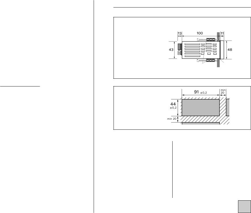
2. SPACE REQUIREMENTS
Case dimensions : (with terminals) 96 x 48 x 124 mm
Fitting panel max. thickness 30
Terminals 
case |
external |
tightenings |
seal |
Panel mounting cut out 44 x 91 mm
Protection :
Front face : IP 65
Case : IP20
Terminals : IP 20
Case :
Self-extinguishing casing of black UL 94 V0 ABS.
Connectors plug-off connectors on rear face for screwed conections (2.5mm², flexible or rigid)
Display : (14 mm) Electroluminescent red (green optional) 4 alarm Leds
bargraph : 16 leds
S
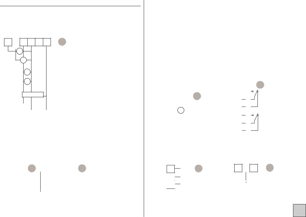
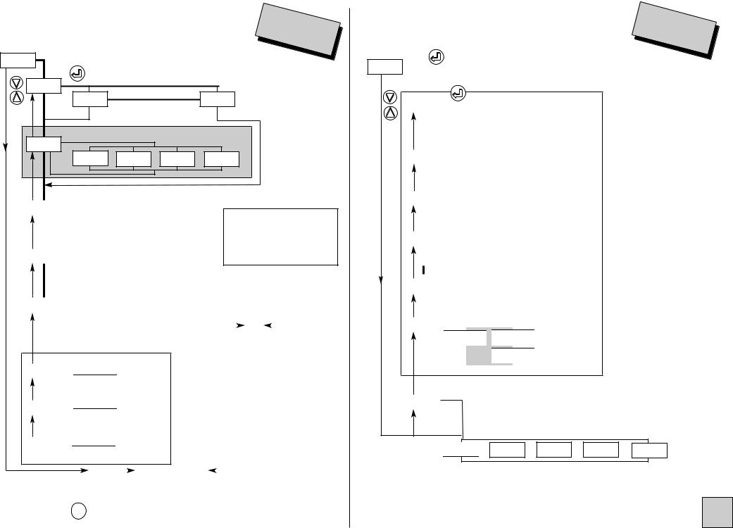
3. WIRING |
|
|
|||
INPUTS |
|
|
|
||
PROCESS |
|
|
|
|
|
4 |
5 6 |
7 |
8 |
A |
|
|
+ 300V - |
|
NC |
|
|
|
+ 1V |
- |
|
|
|
|
10V |
|
|
|
|
|
+ |
mA |
- |
|
|
|
+ |
mV |
- |
|
|
|
|
- |
|
|
+ |
2-
|
|
|
|
3- |
IOUT |
VCC |
|||
LOGIC INPUTS
(optional)
23 |
|
LOG 1 |
C |
|
|
|
E |
|
|
|
|||||
24 |
|
LOG 2 |
|
33 |
|
|
LOG 2 |
|
|
|
|||||
|
|
|
|
|
|
|
|
25 |
|
COM |
|
34 |
|
|
COM |
|
|
|
|
||||
|
|
|
|
|
|
|
|
2 channels |
|
2 channels |
|||||
|
|
|
|
20 |
|
|
|
|
23 |
|
|
|
|
26 |
|
32 |
|
|
|
|
|
|
|
|
|
|
|
|
|
||||
|
|
|
|
|
|
|
|
|
|
|
|
|
|
|
||
|
|
B |
21 |
|
|
|
C |
24 |
|
|
|
|
27 |
|
33 |
|
|
|
|
|
|
|
|
|
D |
28 |
E |
34 |
|||||
|
|
|
|
22 |
|
|
|
|
25 |
|
|
|
29 |
35 |
||
|
|
|
|
|
|
|
|
|
|
|
|
|
|
|
||
|
|
|
|
|
|
|
|
|
|
|
|
|
|
30 |
|
36 |
|
|
|
|
|
|
A |
|
|
|
|
|
|
|
|||
|
|
|
|
|
|
|
|
|
|
|
|
31 |
|
37 |
||
|
|
|
|
|
|
|
|
|
|
|
|
|
|
|
|
|
1 |
2 |
3 |
|
4 |
5 |
6 |
7 |
8 |
9 |
|
|
|
|
|
||
Location of terminals
(view of case rear side)
OUTPU |
(optional) |
|
|
|
|
||||
|
|
|
|
|
2 RELAYS |
D |
|||
|
|
|
|
|
|
|
|
|
|
|
|
|
|
|
26 |
|
T1 |
|
|
|
|
|
|
|
|
|
|||
|
|
|
|
|
|
|
|
|
|
|
|
|
|
|
27 |
|
C1 |
|
|
24 |
|
- |
|
|
|
|
|
|
|
|
|
|
28 |
|
R1 |
|
|
||
|
|
|
|
|
|
|
|
|
|
25 |
|
|
|
|
|
|
|
|
|
|
+ |
|
|
29 |
|
T2 |
|
|
|
|
|
|
|
|
|
||||
|
|
|
|
|
|
||||
|
|
|
|
|
|
|
|
|
|
0-4/20mA active |
|
|
30 |
|
C2 |
|
T : ON |
||
|
|
|
|
|
|
|
|
|
|
|
|
|
|
|
31 |
|
R2 |
|
C : Common |
|
|
|
|
|
|
|
R : OFF |
||
|
|
|
|
|
|
|
|
|
|
|
|
|
|
|
|
|
|
|
|
DIGITAL
B
21 A
22 COM
Data link RS 485
POWER SUPPLY
1 |
2 |
3 |
A |
AC ~ |
|
|
|
~ |
|
|
|
||
|
|
|
||
DC + |
- |
|||
S
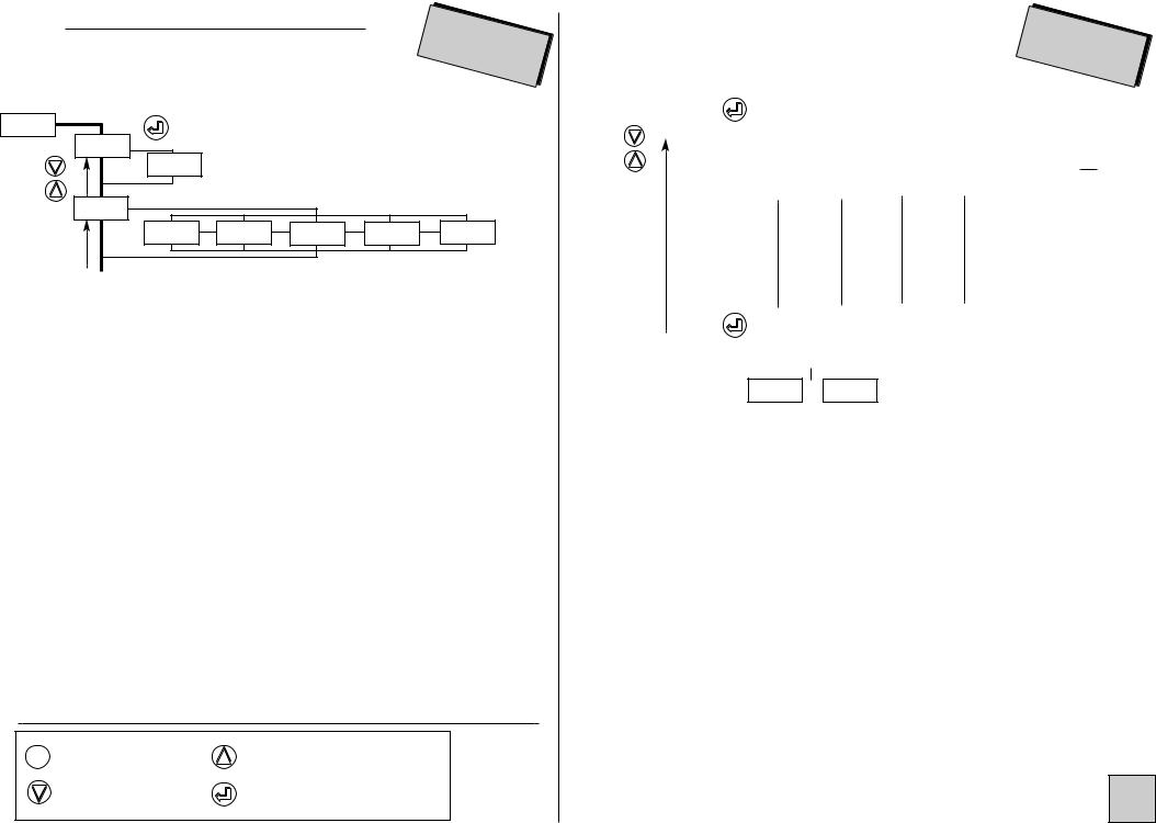
4. PROGRAMMING
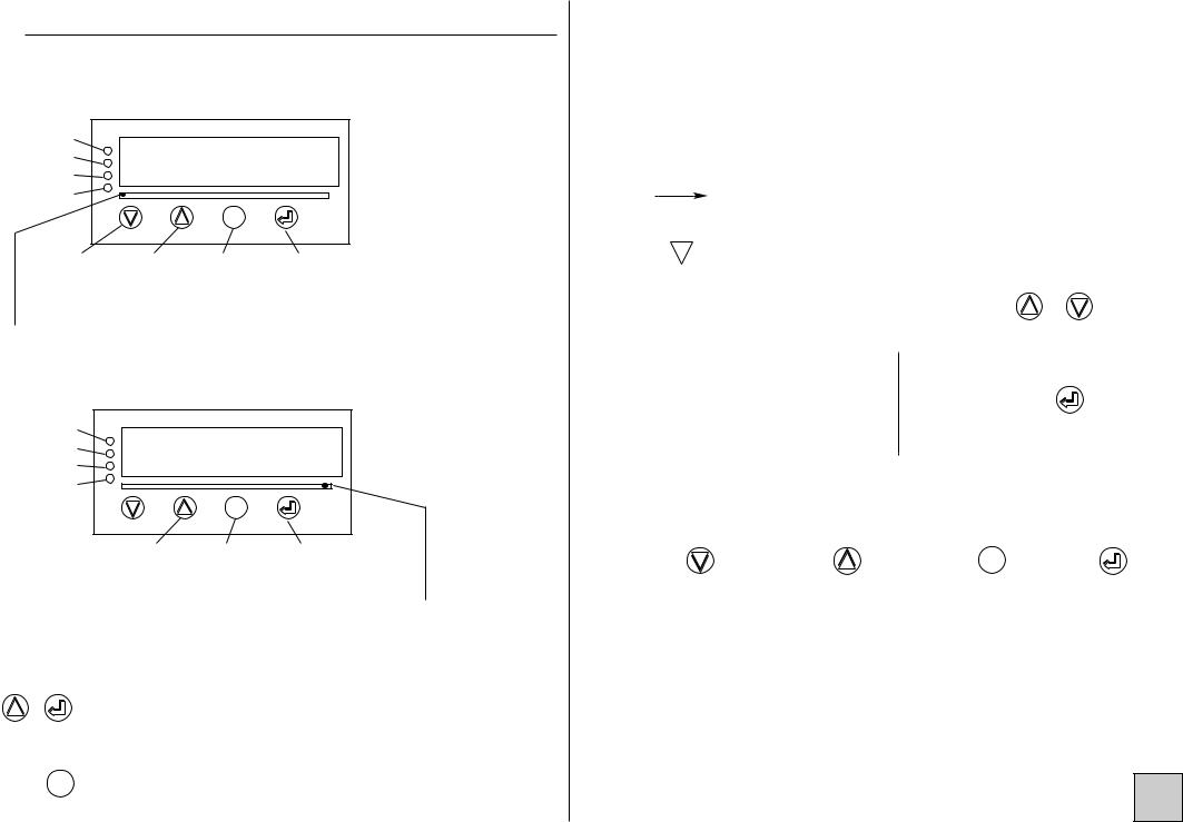
4.1 Communication with the instrument
Functions available from the instant measure :
Alarms |
|
|
|
|
|
|
|
|
Led 1 |
|
|
|
|
|
|
|
|
Led 2 |
|
|
|
|
|
|
|
|
Led 3 |
|
|
|
|
|
|
|
|
Led 4 |
A |
B |
C |
D |
E |
F |
G |
H |
|
|
|
|
|
|
|
|
|
|
|
|
|
|
M |
|
|
|
min. |
Max. value |
Access to |
min. and max. |
display |
display |
the main |
zero reset |
p21 |
p21 |
menu p6 |
p22 |
|
|
||
The Led under marking A blinks to indicate that |
|
||
the displayed value |
the instant value. |
|
|
|
|
|
|
Functions available from the totalizer :
Alarms |
|
|
|
|
|
|
|
|
Led 1 |
|
|
|
|
|
|
|
|
Led 2 |
|
|
|
|
|
|
|
|
Led 3 |
|
|
|
|
|
|
|
|
Led 4 |
A |
B |
C |
D |
E |
F |
G |
H |
|
|
|
|
|
|
|
|
|
|
|
|
|
|
M |
|
|
|
Display of the oversteppings counter. (Hi.tot)
Access to |
Access to |
main |
menu totalizer |
menu |
zero reset |
The Led under marking H blinks to indicate that the displayed value is the cumulated value.
Further functions can be reached by pressing several keys :
+Switching from instant value display to cumulated value display and vice-versa;
 +
+  Direct measure visualisation; (see p24)
 + M
+ M
Only on the instant value display.  +
+  Tare setting; (see p23)
 +
+  Down scale display setting; (see p23)
 +
+  Full scale display setting; (see p23)
|
|
|
|
|
|
Move through main menu |
|
|
|
|
|
|
|
|
|
|
|
|
|
|
|
|
|
Return to previous menu |
|
|
|
|
|
|
|
« |
|
|
|
|
|
|
|
|
|
Blinking display : awaiting validation or setting |
||
|
|
|
|
|
|
Alternate information display |
|
|
|
|
Entering of a parameter : |
|
|
||||
|
86888 |
|
|
First start by increasing or decreasing |
& |
|||
|
|
|
|
|
|
the 1st digit and the sign : from -9 to +9. |
|
|
|
|
|
|
|
|
|||
|
|
86588 |
|
|
||||
|
|
|
|
The 2nd from 0 to 9. |
|
|
||
|
|
|
|
|
|
Between each entering, validate |
||
|
|
|
|
|
||||
|
|
86528 |
|
|
The 3rd from 0 to 9. |
|||
|
|
|
|
the cipher with key |
|
|||
|
|
86520 |
|
|
The 4th from 0 to 9. |
Note : The totalizer |
|
|
|
|
|
|
|
|
|
|
|
|
|
86520 |
|
|
The 5th from 0 to 9. |
parameters are entered on |
||
|
|
|
|
|
|
|
6 digits. |
|
4.2 Orientation through programming
Dialogue is ensured by the 4 keys located on the front face.
|
|
MM |
|
Move through |
Move through |
Exit from a sub- |
Validation of |
menus down- |
menus : upwards, |
menu to access |
the displayed |
wards, |
or increasing of |
next menu / |
parameter, |
decreasing of the |
the displayed |
access to the |
or access to |
displayed value |
value |
programming |
a sub-menu |
|
|
exit menu |
|
Note mode programming, the instrument will automatically resume measuring with the previous configuration if no key is pressed during 1min.
S
|
|
4.3 Main menu |
|
|
|
|
|
|
|
menu |
|
|
|
|
vertical |
|
|
|
|
||||||||||||||||||
|
|
|
|
|
|
|
|
|
|
|
|
|
|
|
|
|
|
|
|
|
|
scroll |
|
|
|
|
move |
|
|
|
|
|
|
||||
|
|
|
|
|
|
|
|
|
|
|
|
|
|
|
|
|
(relay /analog |
|
(analog |
|
|
|
|
|
|
|
|
|
|
|
|
||||||
|
|
|
|
|
|
|
|
|
|
|
|
|
|
|
|
|
output) |
|
|
|
output) |
|
|
|
(relay output) |
|
|
|
|
|
|||||||
|
|
|
|
« |
|
|
|
|
|
« |
|
|
|
|
« |
|
|
|
|
« |
|
|
|
|
|
« |
|
|
|
|
« |
|
|
|
« |
||
|
|
rEAd |
|
|
|
ProG |
|
|
|
|
P.CodE |
|
|
|
SIMUL |
|
|
|
|
GEnE. |
|
|
|
|
CLEAr |
|
|
|
CLr.tA |
|
|||||||
|
|
|
|
|
|
|
|
|
|
|
|
|
|
|
|
|
|
|
|
|
|
|
|
||||||||||||||
|
|
|
|
|
|
|
|
|
|
|
|
|
|
|
|
|
|
|
|
|
|
|
|
|
|
|
|
|
|
|
|
|
|
|
|
|
|
|
|
|
|
|
|
|
|
|
|
|
|
|
|
|
|
|
|
|
|
|
|
|
|||||||||||||||
|
|
|
|
|
|
|
|
|
|
|
|
|
|
|
|
|
|
Display |
|
|
|
|
|
|
|
|
|
Erasing of |
Tare zero |
||||||||
Configuration |
|
Access code |
|
|
|
|
|
Analog |
|
|
|
||||||||||||||||||||||||||
|
|
reading |
|
|
programming |
simulation |
|
|
output |
|
|
|
recorded |
|
|
|
reset |
|
|||||||||||||||||||
|
|
mode |
|
|
|
|
|
|
|
|
|
|
|
|
|
instant or |
|
simulation |
|
|
alarms |
|
|
|
|
|
|
||||||||||
|
|
|
|
|
|
|
|
|
|
|
|
|
|
|
|
|
cumulated |
|
|
|
|
|
|
|
|
|
|
|
|
Authorized |
|
||||||
|
|
|
|
|
|
|
|
|
|
|
|
|
|
|
|
|
value, accor- |
|
Authorized by |
|
|
|
|
|
|
access code |
|||||||||||
|
|
|
|
|
|
|
CodE |
|
|
|
|
|
|
|
|
ding to type |
|
access code |
|
|
|
|
|
|
|
|
|
|
|||||||||
|
|
|
|
|
|
|
|
|
|
|
|
|
|
|
|
|
of display |
|
|
|
|
|
|
|
|
|
|
|
|
|
|
|
|
||||
|
|
|
|
|
|
|
|
|
|
« |
|
|
|
|
|
|
|
|
|
|
|
|
|
|
|
|
|
|
|
|
|
||||||
|
|
|
|
|
88888 |
|
|
|
|
|
|
|
present befo- |
|
|
|
|
|
|
|
|
|
|
|
|
|
|
|
|
||||||||
|
|
|
|
|
|
|
|
|
|
|
|
|
|
|
Entering of the access code. |
|
|||||||||||||||||||||
|
|
|
|
|
|
|
|
|
|
|
|
|
|
|
|
|
re the access |
|
|
|
|||||||||||||||||
|
|
|
|
|
|
|
|
|
|
|
|
|
|
|
|
|
|
|
|||||||||||||||||||
|
|
|
|
|
|
|
|
|
|
|
|
|
|
|
|
|
to the menu |
|
|
The access to the programming |
|
||||||||||||||||
|
|
|
|
|
|
|
|
|
|
|
|
|
|
|
|
|
|
|
menu is protected by a 5-cipher |
|
|||||||||||||||||
|
|
|
|
If code correct, |
|
|
|
|
Authorized by |
|
|
|
|||||||||||||||||||||||||
|
|
|
|
|
|
|
|
|
|
code. |
|
|
|
|
|
|
|
|
|
|
|
|
|||||||||||||||
|
|
|
|
|
|
|
|
access code |
|
|
|
|
|
|
|
|
|
|
|
|
|
|
|||||||||||||||
|
|
|
|
|
access to pro- |
|
|
|
|
|
|
The code on factory exit is 00000 |
|||||||||||||||||||||||||
|
|
|
|
|
|
|
|
|
|
|
|
|
|
|
|
||||||||||||||||||||||
|
|
|
|
|
|
gramming |
|
|
|
|
|
|
|
|
|
|
|
(to change this code, see p20). |
|
||||||||||||||||||
|
|
|
|
|
|
|
menu |
|
|
|
|
|
|
|
|
|
|
|
|
|
|
|
|
|
|
|
|
|
|
|
|
|
|
|
|
|
|
|
|
|
|
|
|
|
|
|
|
|
|
|
|
|
|
|
|
|
|
|
|
|
|
|
|
|
|
|
|
|
|
|
|
|
|
|
|
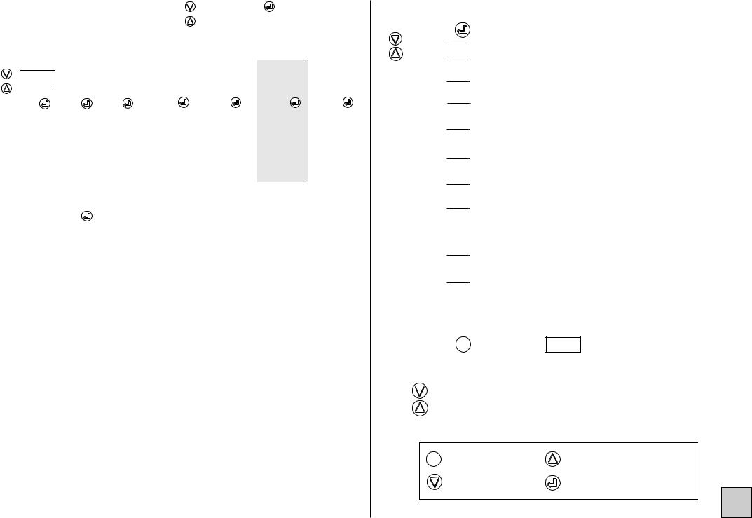
4.4 Programming menu (according to options) |
|
||
|
programming |
p7 |
|
InPut |
|||
|
|
Access to the display factor programming |
p7 |
dISPL. |
|||
|
|
(instant value) |
|
|
|
|
|
totAl. |
After programming the totalizer |
p8 |
|
|
|
Access to the analog output programming |
p8 |
OUt.MA |
|||
|
|
(option analog output) |
|
|
|
|
|
|
|
Access to the communication parameters |
p9 |
JbuS |
|||
|
|
(option digital output) |
|
|
|
|
|
|
|
Access to the programming of the LOGIC inputs |
p9 |
tor |
|||
|
|
(option LOGIC inputs) |
|
|
|
|
|
|
|
Access to the programming of the relays (2 relays) |
p10 |
rELAY |
|||
|
|
(option relay output) |
|
|
|
|
|
|
|
Access to the programming of the output, the relays, |
p11 |
SECU |
|||
|
|
in case of self-diagnosis and/or sensor rupture, and |
|
|
|
|
|
|
|
access to disconnecting the sensor rupture |
|
|
|
(option analog output or relays) |
|
|
|
Access to the display programming : |
p12 |
Pr.diS |
|||
|
|
Bargraph, display brightness |
|
|
|
|
|
|
|
Access to the programming exit menu with or |
p13 |
SAvE |
|||
|
|
without configuration saving |
|
|
|
|
|
Note : |
M to reach menu |
SAvE |
Press |
In mode programming, the instrument will automatically resume measuring with the former configuration if no key is pressed during 1min.
Move through menus / choice
M |
Menu exit / access |
Upwards move / increase |
|
||
|
|
Validation / Vertical move |
S
4.4.1 Input programming |
|
|
|
|
InPut |
||
|
|
|
|
|
|||
InPut |
|
|
|
|
|
|
|
tYPE |
« |
|
|
|
|
|
|
U |
« |
|
|
|
MA |
« |
|
|
|
|
|
|
|
||
|
voltage input |
|
|
current input |
|||
caliber |
|
|
|
voltage input only |
|||
CALib |
« |
|
|
|
|
|
|
0-10 |
|
« |
0-0.1 |
« |
|
« |
|
|
300 |
0-1 |
|||||
|
|
|
|
||||
|
|
|
|
down scale |
||
d.in |
|
« |
|
« |
||
|
|
|
|
|||
|
|
|
|
-888.88 |
in mV, V or mA |
|
|
|
(1) |
according to |
|||
|
|
|
|
full scale |
the type |
|
|
|
|
|
|
||
|
|
|
« |
|
|
|
F.in |
|
|
|
|
|
|
|
|
|
|
« |
||
|
|
|
|
-888.88 |
in mV, V or mA |
|
|
|
(1) |
according to |
|||
|
|
|
|
|
|
the type |
(1)-22.00 < x < 22.00 (mA) -11.00 < x < 11.00 (10V)
-320.0 < x < 320.0 (300V) -110.0 < x < 110.0 (0.1V) -1.100 < x < 1.100 (1V)
|
|
|
|
« |
|
|
|
|
|
|
|
|
|
|
|
|
|
|
|
|
|
|
|
Funct. |
|
|
|
|
|
|
|
|
|
|
|
|
|
|
|
|
|
|
|
« |
|
|
|
|
Li.SPE |
|
« |
|
|
|
|
|
|
|
|
« |
|
root |
||||||
|
|
|
|
|
|
|
|
|
|
|
LinEA. |
|
|
|
||||||||
|
|
|
|
|
|
linear |
|
|
linear |
|
|
|
function square |
|||||||||
|
|
|
|
|
|
|
|
|
|
|
|
function |
|
|||||||||
|
|
|
|
|
|
|
|
|
|
|
|
|
root extraction |
|||||||||
|
|
|
|
|
|
|
|
|
|
|
|
|
|
|
|
|
|
|||||
|
|
Special |
|
|
|
only |
|
|
|
|
|
|
|
|
|
|
|
|
|
|||
|
nb |
|
« |
|
|
« |
|
|
|
|
|
|
|
|
|
|
|
|
|
|
||
|
|
|
|
|
|
|
|
|
|
|
|
|
|
|
|
|
|
|
||||
|
|
|
|
|
|
|
|
|
|
|
|
|
|
|
|
|
|
|||||
|
|
|
|
|
000018 |
from 1 to 18 |
|
|
|
|
|
|
|
|
|
|
|
|
||||
|
|
|
|
|
|
|
|
|
|
|
|
|
|
|
|
|
||||||
|
|
|
|
« |
|
|
|
|
|
|
|
|
|
|
|
|
|
|
|
|
|
|
|
A01 |
|
|
|
|
« |
|
|
|
|
|
|
|
|
|
|
|
|
|
|
||
|
|
|
|
|
|
|
|
|
|
|
|
|
|
|
|
|
|
|
|
|
||
|
|
|
|
(1) |
-888.88 |
|
|
|
|
|
|
|
|
|
|
|
|
|
|
|||
|
|
|
|
|
|
|
|
|
|
|
|
|
|
|
|
|
|
|||||
|
|
|
|
|
|
|
|
|
|
|
|
|
|
|
|
|
|
|
|
|
|
|
|
|
|
|
« |
|
|
|
|
|
|
|
|
|
|
|
|
|
|
|
|
|
|
|
A18 |
|
|
|
|
« |
|
|
|
|
|
|
|
|
|
|
|
|
|
|
||
|
|
|
|
|
|
|
|
|
|
|
|
|
|
|
|
|
|
|
||||
|
|
|
-888.88 |
|
|
|
|
|
|
|
|
|
|
|
|
|
|
|||||
|
|
|
(1) |
|
|
|
|
|
|
|
|
|
|
|
|
|
|
|||||
|
|
|
|
|
|
|
|
|
|
|
|
|
|
|
|
|
|
|
|
|
||
|
|
|
|
|
|
|
|
|
|
|
|
|
|
|
|
|
|
|
|
|
|
|
|
|
|
|
|
|
|
|
|
|
diSPL. |
|
|
|
|
|
|
|
|
|
|
||
Note : |
|
|
|
|
|
|
|
|
|
|
|
|
|
|
|
|
|
|
|
|
||
|
|
|
|
|
|
|
diSPL. |
|
|
|
|
|
|
|
|
|
||||||
Press key |
|
to reach menu |
|
|
|
|
|
|
|
|
||||||||||||
|
|
|
|
|
|
|
|
|
|
|
|
|
|
|||||||||
4.4.2 Display programming |
diSPL |
(instant value) |
. |
|
dISPL.
«
|
|
|
|
|
|
|
|
|
|
|
|
|
|
|
|
|
|
|
|
|
|
« |
|
|
|
|
|
|
|
location |
|
||||
|
Point |
|
|
|
|
|
« |
|
|
|
|||||||
|
|
|
|
|
|
|
|
|
|
|
|
|
|||||
|
|
|
|
|
|
|
-- |
|
|
* |
|
|
|
|
|
|
|
|
|
|
|
|
|
|
|
|
|
|
|
|
|
|
|
||
|
|
|
|
|
|
|
|
|
|
|
|
|
|
|
|
|
|
|
|
|
|
« |
|
|
|
|
|
display corresponding to |
|
||||||
|
d.diSP |
|
|
|
|
|
« |
|
|||||||||
|
|
|
|
|
|
|
|
|
|
input down scale “d.in” |
|
||||||
|
|
|
|
|
|
|
.888 |
|
|||||||||
|
|
|
|
|
|
|
|
||||||||||
|
|
|
|
|
|
|
|
|
|
|
|
|
|
|
|
|
|
|
|
|
|
« |
|
|
|
|
|
|
|
|
|
|
|
|
|
|
F.diSP |
|
|
|
|
|
« |
display corresponding to |
|
||||||||
|
|
|
|
|
|
|
|
|
|
input full scale “F.in” |
|
||||||
|
|
|
|
.888 |
|
||||||||||||
|
|
|
|
|
|
|
|
||||||||||
|
|
|
|
|
|
|
|
|
|
|
|
|
|
|
|
|
|
|
|
|
|
|
|
|
|
|
|
|
|
|
|
|
|
|
|
|
|
|
|
« |
|
|
|
|
|
|
|
special linearisation |
|
|
|||
|
b01 |
|
|
|
|
|
|
|
|
|
|
|
|
||||
|
|
|
|
|
|
« |
setting in display points of |
|
|
||||||||
|
|
|
|
|
|
.888 |
the same number of ordi- |
|
|
||||||||
|
|
|
|
|
|
|
|
|
|
|
nates “bxx” and |
|
|
||||
|
|
|
|
|
|
|
|
|
|
|
|
|
|||||
|
|
|
« |
|
|
|
|
|
abscisses “Axx” |
|
|
||||||
|
|
|
|
|
|
|
|
|
|
||||||||
|
b18 |
|
|
|
|
|
« |
|
|
|
|
|
|
|
|||
|
|
|
|
|
|
|
|
|
|
|
|
|
|||||
|
|
|
|
|
|
|
.888 |
|
|
|
|
|
|
|
|||
|
|
|
|
|
|
|
|
|
|
|
|
|
|
|
|
|
|
|
|
|
|
|
« |
|
|
|
|
|
|
|
|
|
|
|
|
|
Cut.oF |
|
|
|
|
|
|
|
|
|
|
« |
|
|
|
|
|
|
|
|
|
|
|
|
|
|
|
|
|
|
|
|
|
|
|
|
|
|
|
|
|
|
|
« |
|
|
|
|
|
|
|
||
|
|
|
|
|
|
|
|
|
|
|
YES |
|
|
|
|
|
|
|
|
|
|
|
|
|
|
|
|
|
|
|
« |
|
setting in display |
|
|
|
|
|
|
|
|
|
|
|
|
|
|
- 88.888 |
|
||||
|
|
|
|
|
|
|
|
|
|
|
|
|
|
|
points |
|
|
|
|
|
|
|
|
|
|
|
|
|
|
|
|
|
|
|
|
|
|
|
|
|
|
|
|
|
|
|
|
|
|
|
|
|
|
|
|
|
|
|
integration indice |
|
|
|
|
|
|||||||
|
IntEG. |
|
« |
|
|
« |
|
|
|
|
|
|
|
|
|||
|
|
|
|
|
|
|
|
|
|
|
|
|
|
||||
|
|
|
|
000000 |
|
|
IntEG : coefficient from 0 to 10 |
||||||||||
|
|
|
|
|
|
||||||||||||
|
|
|
|
|
|
|
|
|
|
|
|
|
|
|
|
|
|
* Changing this parameter requires re-programming following parameters related to the relays, the analog output, the bargraph according to their dedication, as well as following display parameters :
SPxx, hystx, do.diS, Fo.diS d.bArG, F.bArG, d.diSP, FdiSP, bxx, Cut.oF

 or JbuS or tor or rELAY or SECU
according to options
S

4.4.3 Totalizer programming
totAL. |
« |
|
dP.tot |
« |
|
|
|
|
|
.-- |
« |
totalizer decimal point |
||||
|
|
location |
|
|
||
|
|
|
* |
|
|
|
Auto.P |
« |
|
|
|
|
|
|
« |
nO |
«automatic |
|||
|
|
|
decimal pt |
|||
t.bASE |
« |
|
|
|
|
|
|
« |
60 |
« |
3600 |
« |
|
|
|
|
|
|
||
Coeff |
« |
|
|
integration time |
||
|
« |
coefficient setting from |
||||
|
.888 |
|||||
|
|
|
±0,0001 to +999 999 |
|||
|
|
|
|
or -99 999 |
||
M.deF.
«
«
YES |
« |
|
« |
||
|
88888.8
time setting for the recording of defects from 0 to 25.0
TotAl
* Changing this parameter requires re-programming following parameters related to the relays, the analog output, the bargraph according to their dedication
SPxx, hystx, do.diS, Fo.diS d.bArG, F.bArG,
Out.MA or |
JbuS |
or |
tor |
or |
rELAY |
or |
SECU |
according to options
4.4.4 Analog output programming
Option analog output |
Out |
|
|
. |
|
|
|
MA |
Out.MA 
0 |
« |
parameter dedicated to the output |
|||
|
In5tA |
« |
totAL |
« |
|
|
|
|
|
||
|
« |
(4) |
|
|
« |
(4) |
|
diS |
« |
|
|
diS |
« |
|
|
|
|
output down scale |
||
.88 |
|
« |
00.00 |
< x < 22.00 (mA) |
|
(4) |
|||
|
|
|
00.00 |
< x < 11.00 (V) |
|
|
|
||
analog output full scale |
||||
.88 |
|
« |
|
|
|
|
|
|
|
display corresponding to output down scale
.88 |
« |
|
display corresponding to output full scale
.88 |
« |
|
|
JbuS or tor |
or rELAY or SECU |
|
|
according to options |
|
|
See |
output features p17 |
|
|
PressNote : M to go on to next menu |
Move through menus / choice |
|
|
M Menu exit / access |
Upwards move / increase |
|
|
|
|
||
|
|
Validation / vertical move |
S |
|
|
|
|
4.4.5 Progr |
|
|
|
JBuS |
|
|
|
|
|
|
|
|
Option digital output |
|
JBuS |
« |
|
|
|
SLAvE |
|
|
|
|
|
-8888 |
« |
|
|
|
|
must be included between 1 and |
|
|
bAUd |
« |
transmission speed (baud rate) |
|
|
|
|
|
|
|
19200 |
« |
9600 |
« |
4800 |
« |
2400 |
« |
1200 |
« |
|
|
|
|
|
|
|
|
« |
|
time delay before any response |
|||||||||||
|
dELAY |
|
|
|
|
|
|
|
|
|
|
|
|
|
|
|
|
|
|
|
|
|
|
|
|
|
|
|
|
|
|||
|
|
|
|
|
|
« |
|
|
|
|
« |
|
||||
|
|
|
|
|
On |
|
|
|
OFF |
|
|
|||||
On : delay = 75ms |
|
|
|
|
|
OFF : delay = 20ms |
||||||||||
|
|
|
|
|
or |
|
|
|
|
|
|
|
|
|
|
|
|
|
tor |
|
rELAY |
or |
SECU |
See also the features of the |
|||||||||
|
|
|
|
|
|
|
|
|
|
|
|
|
|
|
|
digital data link |
|
|
|
|
|
|
|
|
|
|
|
|
|
|
|
|
|
4.4.6 Programming of the LOGIC inputs |
|
|
|
|
ToR |
|
|
|
||||||||||||||||||||||||
|
|
|
|
|
|
|
|
|
|
|
|
Option LOGIC inputs |
|
|
|
|
|
|||||||||||||||
|
|
|
|
|
|
|
|
|
|
|
|
|
|
|
|
|
|
|
|
|
|
|
|
|
|
|
|
|
|
|
||
tor |
|
|
|
« |
|
|
|
|
|
|
|
|
|
|
|
|
|
|
|
|
|
|
|
|
|
|
|
|
|
|
||
|
|
|
|
|
|
|
|
|
|
|
|
|
|
|
|
|
|
|
|
|
|
|
|
|
|
|
|
|
||||
|
|
tor 1 |
|
|
|
|
|
|
|
|
|
|
|
|
|
|
|
|
|
|
|
|
|
|
|
|
|
|
|
|
|
|
|
|
|
|
|
|
|
|
|
« |
|
|
|
« |
|
|
« |
|
|
|
« |
|
|
|
|
|
|
|
|
|
|||
|
|
|
|
|
|
dSP.to |
|
CLr.M |
|
HoLd |
|
tArE |
|
|
totAL |
|
|
|
|
« |
|
|
|
|
|
« |
||||||
|
|
|
|
|
|
|
|
|
|
|
|
|
|
|
|
|
|
|
|
|
|
|
|
Fct1 |
|
|
|
|
Fct5 |
|
||
|
|
|
|
switching |
function |
function |
function |
|
|
function totalizer |
|
|
|
|||||||||||||||||||
|
|
|
|
|
between |
min. |
|
display |
|
tare |
|
|
see p14 |
|
|
|
|
|
|
|
|
|
||||||||||
|
|
|
instant value |
and |
|
hold |
|
(on |
|
|
|
|
|
|
|
|
|
|
|
|
|
|
|
|||||||||
|
|
|
/ cumulated |
max. 0 |
|
|
|
|
instant |
|
|
|
|
|
|
|
|
|
|
|
|
|
|
|
||||||||
|
|
|
|
|
|
value |
reset |
|
|
|
|
|
value |
|
|
|
|
|
|
|
|
|
|
|
|
|
|
|
||||
|
|
|
|
|
|
|
|
|
(instant |
|
|
|
|
only) |
|
|
|
|
|
|
|
|
|
|
|
|
|
|
|
|||
|
|
|
|
|
|
|
|
|
value) |
|
|
|
|
|
|
|
|
|
|
|
|
|
|
|
|
|
|
|
|
|
||
|
|
|
|
|
« |
|
|
|
|
|
|
|
|
|
|
|
|
|
|
|
|
|
|
|
|
|
|
|
|
|
|
|
|
|
tor 2 |
|
|
Idem Tor 1 |
|
|
|
|
|
|
|
|
|
|
|
|
|
|
|
|
|
|
|
|
|
|
|||||
|
|
|
|
|
|
|
|
|
|
|
|
|
|
|
|
|
|
|
|
|
|
|
|
|
|
|
|
|
|
|
|
|
rELAY or SECU
See also the features of the LOGIC input
M |
Menu exit / access |
Upwards move / increase |
|
S
 Loading...