


09/97
Electromagnetic flowmeters
Installation instructions
for water and seewage |
|
|
|
|
AQUAFLUX |
• Primary head |
|
|
F |
||
• Compact flowmeters |
010 K |
|
|
|
020 K |
|
|
080 K |
CONTENTS |
|
Storage and transport |
Pagesn 3-4 |
Installation in the pipeline |
Pages 4-5 and 7-8 |
Grounding |
Pagen 9 |
AQUAFLUX F
AQUAFLUX 010 K / 020 K |
|
AQUAFLUX 080 K |
|
|
|
|
|
|
|
|
|
|
|
|
|
|
|
3.1M68EA1 099721 |
Order No. DIN size 7.02137.33.00 |
|
US size 7.02137.73.00 |

Contents
System description |
2 |
|
Product liability and warranty |
2 |
|
Standards and approvals |
2 |
|
Items included with supply |
3 |
|
1 |
Important information for installation: PLEASE NOTE |
4-5 |
2 |
Suggestions for installation |
5 |
3 |
Instrument nameplate |
6 |
4 |
Flowmeter versions |
6 |
5 |
Installation in the pipeline |
7 |
6 |
Torques |
8 |
7 |
Grounding |
9 |
8 |
Replacement of separate primary head |
10 |
9 |
Technical data |
10-11 |
10 |
Dimensions and weights |
12-13 |
11 |
Limits |
14 |
Printed form to accompany flowmeters returned to Krohne |
15 |
|
System description
AQUAFLUX electromagnetic flowmeters are precision measuring instruments designed for the linear flow measurement of process liquids.
The process liquids must be electrically conductive: |
³ 20 mS/cm for demineralized cold water |
|||||
The full-scale range Q100% can be set as a function of the meter size: |
|
|||||
AQUAFLUX 010 K / 020 K / 080 K: |
DN 10 - 1000 |
/ |
3/8” - 040” |
Q100% |
= 0.1 - 033 900 m3/hr = 0.02 |
- 1156 640 US GPM |
AQUAFLUX F: |
DN 10 - 3000 |
/ |
3/8” - 120” |
Q100% |
= 0.1 - 305 000 m3/hr = 0.02 |
- 1 400 000 US GPM |
This is equivalent to a flow velocity of 0.3 - 12 m/s, or 1 - 40 ft/s.
Product liability and warranty
AQUAFLUX electromagnetic flowmeters are designed solely for measuring the volumetric flowrate of electrically conductive, liquid process products.
Flowmeters with AQUAFLUX primary heads are not certified for use in hazardous locations. Other flowmeters series are available for such applications.
Responsibility as to suitability and intended use of these electromagnetic flowmeters rests solely with the operator.
Improper installation and operation of the flowmeters (systems) may lead to loss of warranty.
In addition, the ”General conditions of sale” forming the basis of the purchase contract are applicable.
If AQUAFLUX flowmeters need to be returned to Krohne, please note the information given on the last-but-one page of this manual. Krohne regret that they cannot repair or check your flowmeter(s) unless accompanied by the completed form sheet.
Standards and approvals
Please refer to the installation and operating instructions for the signal converter.
2
Items included with supply
AQUAFLUX F primary heads
•Primary head in the size as ordered
•Connecting wires for grounding, refer to Section 7 ”Grounding”
•Certificate of calibration data
•Grounding rings (optional), if ordered
•Installation instructions
AQUAFLUX 010 K, 020 K and 080 K compact flowmeters
•Compact flowmeter in the size as ordered
•Connecting wires for grounding, see Section 7 ”Grounding”
•Certificate of calibration data
•Grounding rings (optional), if ordered
•Installation instructions
•Installation and operating instructions for the signal converter
Fitting accessories (stud bolts, nuts, gaskets, etc.) are not supplied with the flowmeter, to be provided by customer!
Handling
Do not lift flowmeter by the signal converter housing or the terminal box.
Do not set flowmeter down on signal converter housing or terminal box.
PLEASE NOTE
the temperature limits for storage and transport, see Page 4.
3
1Important information for installation: PLEASE NOTE !
•Use only solventless detergents to clean the signal converter housing (polycarbonate).
•Temperatures
Refer to Section 11 ”Limits” for operating pressure and vacuum load based on flange standards and type of tube liner.
|
Ambient temperature |
|
|
Process temperature |
|
|
|
|
|
||
Compact systems |
-25 to +60 °C (-13 to + 140 |
°F) |
-25 to ≤ +60 °C (-13 to ≤ +140 °F) |
||
|
|
|
|
|
|
|
-25 to +40 |
°C (-13 to + 104 |
°F) |
-25 to ≤ +90 °C (-13 to ≤ +194 °F) |
|
|
|
|
|
|
|
AQUAFLUX F |
-25 to +60 |
°C (-13 to +140 |
°F) |
-25 to > + 60 °C (-13 to > + 140 °F) |
|
|
|
|
|
|
|
In storage |
-20 to +60 |
°C (-04 to +140 |
°F), kept immobile, |
||
|
avoid moisture and sunlight. |
|
|||
|
|
|
|
|
|
Transport |
-05 to +50 |
°C (- 04 to +140 |
°F), |
|
|
|
avoid moisture and sunlight. |
|
|||
|
|
|
|
|
|
• Location and position as required, |
|
|
|
but electrode axis X – • – • – • – X |
|
Y |
|
must be approximately horizontal in a |
|
|
|
|
|
|
|
horizontal pipe run. |
|
|
|
Y terminal box or converter housing |
X |
|
X |
•Measuring tube must be completetly filled at all times.
•Direction of flow is arbitrary. Arrow on flowmeter can normally be ignored.
For exceptions, refer to Section ”Factory settings” in the installation and operating instructions for the signal converter.
•Stud bolts and nuts: to fit, make sure there is sufficient room next to the pipe flanges.
•Vibration: support the pipeline on both sides of the compact flowmeter.
Level of vibration in conformity with IEC 068-2-34: below 2.2g for compact flowmeters in the frequency range of 20-50 Hz with the IFC 010 K / IFC 020 K and 20-150 Hz with the IFC 090 K.
•Do not expose to direct sunlight,
fit a sunshade if necessary, not included with flowmeter, to be provided by customer.
•Large meter sizes (³ DN 200 / ³ 8”): use adapter pipes to allow axial shifting of the counterflanges and to facilitate installation.
4
•Strong electromagnetic fields, avoid in vicinity of flowmeter
•Straight inlet run minimum of 5 × DN and outlet run minimum of 2 × DN,
(DN = meter size), measured from the electrode axis.
•Vortex and corkscrew flow: increase length of inlet and outlet runs or install flow conditioners.
•Mixing different process liquids: install flowmeter upstream of mixing point or at an adequate distance downstream (minimum of 30 × DN), otherwise display may be unsteady.
•Plastic pipes and internally coated metal pipelines: grounding rings required, see Section 7 ”Grounding”.
•Insulated pipeline: do not insulate flowmeter
•Zero setting not necessary. To check, it should be possible to set ”zero” flow velocity in the completely filled measuring tube. Shutoff valves should therefore be provided either downstream of the flowmeter or upstream and downstream of the flowmeter.
2 Suggestions for installation
To avoid measuring errors due to gas/air inclusion or to pipe running empty, please observe the following:
Highest point of pipe run
(Air bubbles collect in measuring tube - faulty measurements!)
Preferred locations
Downpipe
”Zero” flow velocity. Line drained. Faulty
measurements!
Horizontal pipe run
Install in slightly ascending pipe section. If not possible, assure adequate velocity to prevent air, gas or vapor from collecting in
uppper part of flow tube.
Open feed or discharge
Install meter in low section of pipe.
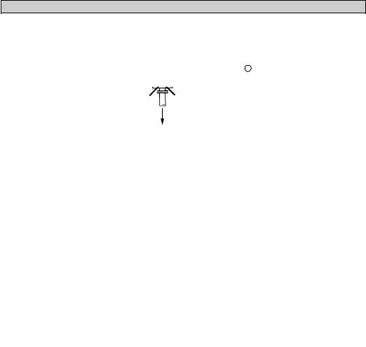
Downpipe over 5 m (16 ft) length
Install air valve X downstream of flowmeter.
5m |
ft16 |
> |
> |
Long pipeline
Always install control and shutoff valves downstream of flowmeter.
Pumps
Never install flowmeter on pump suction side.
open discharge
5
 Loading...