


 ALTOSONIC V12 Handbook
12-chord ultrasonic gas flowmeter for custody transfer
© KROHNE 04/2013 - 4002643502 - MA ALTOSONIC V12 R02 en
:IMPRINT :::::::::::::::::::::::::::::::::::::::
All rights reserved. It is prohibited to reproduce this documentation, or any part thereof, without the prior written authorisation of KROHNE Messtechnik GmbH.
Subject to change without notice.
Copyright 2013 by
KROHNE Messtechnik GmbH - Ludwig-Krohne-Str. 5 - 47058 Duisburg (Germany)
2 |
www.krohne.com |
04/2013 - 4002643502 - MA ALTOSONIC V12 R02 en |

|
|
|
CONTENTS |
|
|
||
|
ALTOSONIC V12 |
|
|||||
|
|
|
|
|
|
||
1 |
Safety instructions |
7 |
|
||||
|
|
|
|
|
|
|
|
|
|
|
1.1 |
Intended use ..................................................................................................................... |
7 |
|
|
|
|
|
1.2 |
Certifications .................................................................................................................... |
7 |
|
|
|
|
|
1.3 |
Safety instructions from the manufacturer ..................................................................... |
8 |
|
|
|
|
|
1.3.1 Copyright and data protection ................................................................................................ |
8 |
|
||
|
|
|
1.3.2 Disclaimer ............................................................................................................................... |
8 |
|
||
|
|
|
1.3.3 Product liability and warranty ................................................................................................ |
9 |
|
||
|
|
|
1.3.4 Information concerning the documentation........................................................................... |
9 |
|
||
|
|
|
1.3.5 Warnings and symbols used................................................................................................. |
10 |
|
||
|
|
|
1.4 |
Safety instructions for the operator............................................................................... |
10 |
|
|
|
|
2 Device description |
11 |
|
|||
|
|
|
|
|
|
||
|
|
|
2.1 |
Scope of delivery............................................................................................................. |
11 |
||
|
|
|
2.2 |
Hardware description..................................................................................................... |
11 |
||
|
|
|
2.2.1 Transducers .......................................................................................................................... |
12 |
|
||
|
|
|
2.2.2 The electronic unit ................................................................................................................ |
13 |
|
||
|
|
|
2.3 |
Software description ...................................................................................................... |
14 |
||
|
|
|
2.4 |
Nameplates .................................................................................................................... |
15 |
||
3 |
Installation |
17 |
|
||||
|
|
|
|
|
|
||
|
|
|
3.1 |
Notes on installation ...................................................................................................... |
17 |
||
|
|
|
3.2 |
Storage ........................................................................................................................... |
17 |
||
|
|
|
3.3 |
Transport ........................................................................................................................ |
18 |
||
|
|
|
3.4 |
Pre-installation requirements ....................................................................................... |
19 |
||
|
|
|
3.5 |
Installation...................................................................................................................... |
19 |
||
|
|
|
3.5.1 Mounting position.................................................................................................................. |
19 |
|
||
|
|
|
3.5.2 Pipe diameters and lengths.................................................................................................. |
20 |
|
||
|
|
|
3.5.3 Flow conditioners.................................................................................................................. |
20 |
|
||
|
|
|
3.5.4 Inlet and outlet for uni-directional use ................................................................................ |
20 |
|
||
|
|
|
3.5.5 Control valves........................................................................................................................ |
21 |
|
||
|
|
|
3.5.6 P and T sensors..................................................................................................................... |
22 |
|
||
|
|
|
3.6 |
Temperatures................................................................................................................. |
23 |
||
|
|
4 Electrical connections |
24 |
|
|||
|
|
|
|
|
|
||
|
|
|
4.1 |
Safety instructions.......................................................................................................... |
24 |
||
|
|
|
4.2 |
Opening and closing covers ........................................................................................... |
24 |
|
|
|
|
|
4.3 |
Digital I/O connections ................................................................................................... |
25 |
||
|
|
|
4.3.1 Pulse and frequency output.................................................................................................. |
26 |
|
||
|
|
|
4.3.2 Status outputs ....................................................................................................................... |
26 |
|
||
|
|
|
4.3.3 Emulation of a turbine meter ............................................................................................... |
27 |
|
||
|
|
|
4.4 |
Serial data communication (RS 485).............................................................................. |
28 |
||
|
|
|
4.5 |
Power connection ........................................................................................................... |
28 |
||
|
|
|
4.6 |
Cabling............................................................................................................................ |
29 |
|
|
|
|
|
4.7 |
Grounding ....................................................................................................................... |
30 |
||
04/2013 - 4002643502 - MA ALTOSONIC V12 R02 en |
www.krohne.com |
3 |

|
CONTENTS |
ALTOSONIC V12 |
|
|
|
||
|
|
|
|
5 Start-up |
31 |
|
5.1 |
Starting the signal converter ......................................................................................... |
31 |
6 Operation |
32 |
|
6.1 |
Display and operating elements .................................................................................... |
32 |
6.1.1 Display in measuring mode with 2 or 3 measured values ................................................... |
33 |
|
6.2 |
Menu overview................................................................................................................ |
34 |
6.3 |
Access control and seals................................................................................................ |
35 |
7 Software service tool |
37 |
|
7.1 |
Introduction .................................................................................................................... |
37 |
7.2 |
Installation of the software ............................................................................................ |
37 |
7.3 |
Starting a session........................................................................................................... |
37 |
7.4 |
Loading a monitoring configuration............................................................................... |
42 |
7.5 |
Changing and saving a monitoring configuration .......................................................... |
45 |
7.5.1 Creating a monitoring configuration .................................................................................... |
45 |
|
7.5.2 Saving a monitoring configuration with a new name ........................................................... |
48 |
|
7.5.3 Saving a monitoring configuration with its current name ................................................... |
49 |
|
7.6 |
Creating a monitoring configuration.............................................................................. |
50 |
7.7 |
Viewing data.................................................................................................................... |
52 |
7.7.1 Unformatted data.................................................................................................................. |
53 |
|
7.8 |
Customizing the way data is presented ......................................................................... |
54 |
7.8.1 Setting up tabs in the user view window .............................................................................. |
54 |
|
7.8.2 Creating a new grid definition............................................................................................... |
56 |
|
7.8.3 Creating a new graphical presentation ................................................................................ |
60 |
|
7.9 |
Creating reports ............................................................................................................. |
61 |
7.9.1 Reporting related to parameter settings ............................................................................. |
61 |
|
7.9.2 Reporting related to process values .................................................................................... |
66 |
|
7.9.3 Reporting related to calibration parameters ....................................................................... |
66 |
|
7.9.4 Reporting related to privileges............................................................................................. |
66 |
|
7.10 Logging data from a flowmeter.................................................................................... |
66 |
|
7.11 Customizing the data logging process......................................................................... |
67 |
|
7.12 Adjusting parameter settings....................................................................................... |
72 |
|
8 Service |
73 |
|
8.1 |
Periodic maintenance..................................................................................................... |
73 |
8.2 |
Cleaning.......................................................................................................................... |
73 |
8.3 |
Exchange of transducers................................................................................................ |
74 |
8.4 |
Exchange of transducers - Depressurised condition .................................................... |
74 |
8.5 |
Exchange of transducers - Pressurised condition ........................................................ |
79 |
8.5.1 Transducer retraction tool.................................................................................................... |
81 |
|
8.5.2 Procedure to remove a transducer ...................................................................................... |
82 |
|
8.6 |
Exchange of electronics unit .......................................................................................... |
94 |
8.6.1 Field version.......................................................................................................................... |
94 |
|
8.7 |
Battery maintenance ...................................................................................................... |
96 |
8.8 |
Availability of services .................................................................................................... |
96 |
4 |
www.krohne.com |
04/2013 - 4002643502 - MA ALTOSONIC V12 R02 en |

|
|
CONTENTS |
|
|
ALTOSONIC V12 |
|
|
|
|
|
|
8.9 Returning the device to the manufacturer..................................................................... |
96 |
8.9.1 General information.............................................................................................................. |
96 |
8.9.2 Form (for copying) to accompany a returned device............................................................ |
97 |
8.10 Disposal ........................................................................................................................ |
97 |
9 Technical data |
98 |
9.1 Measuring principle........................................................................................................ |
98 |
9.2 Transit time measuring principle .................................................................................. |
98 |
9.3 Swirl compensation........................................................................................................ |
99 |
9.4 Multipath ultrasonic flowmeters.................................................................................. |
100 |
9.5 Technical data table ..................................................................................................... |
101 |
9.6 Dimensions and weights .............................................................................................. |
105 |
9.7 Flow table ..................................................................................................................... |
110 |
10 Modbus protocol description and set-up |
111 |
10.1 Introduction ................................................................................................................ |
111 |
10.2 Physical Communication Layer.................................................................................. |
111 |
10.3 Serial transmission format ........................................................................................ |
112 |
10.3.1 ASCII mode........................................................................................................................ |
112 |
10.3.2 RTU mode.......................................................................................................................... |
113 |
10.4 Modbus message framing.......................................................................................... |
113 |
10.4.1 Address Field (Device Address)........................................................................................ |
114 |
10.4.2 Function Field ................................................................................................................... |
114 |
10.4.3 Data Field .......................................................................................................................... |
114 |
10.4.4 Error checking methods ................................................................................................... |
114 |
10.4.5 Transmission gaps............................................................................................................ |
115 |
10.4.6 Time out............................................................................................................................. |
115 |
10.5 Supported functions ................................................................................................... |
115 |
10.5.1 Function 01: READ COILS ................................................................................................. |
116 |
10.5.2 Function 02: READ DISCRETE INPUTS............................................................................. |
116 |
10.5.3 Function 03: READ HOLDING REGISTERS........................................................................ |
117 |
10.5.4 Function 04: READ INPUT REGISTERS............................................................................. |
117 |
10.5.5 Function 05: WRITE SINGLE COIL .................................................................................... |
118 |
10.5.6 Function 06: WRITE SINGLE HOLDING REGISTER........................................................... |
118 |
10.5.7 Function 08: DIAGNOSTICS............................................................................................... |
118 |
10.5.8 Function 15: WRITE MULTIPLE COILS ............................................................................. |
119 |
10.5.9 Function 16: WRITE MULTIPLE HOLDING REGISTERS.................................................... |
119 |
10.5.10 Exception responses ....................................................................................................... |
120 |
10.6 Handling of large data types ...................................................................................... |
121 |
10.6.1 Integer (16 bit), Transmit sequence.................................................................................. |
122 |
10.6.2 Long integer (32 bit), Transmit Sequence ........................................................................ |
122 |
10.6.3 Single precision floating point (32 bit), transmit sequence ............................................. |
123 |
10.6.4 Double precision floating point (64 bit), transmit sequence ............................................ |
124 |
10.6.5 Long long (64 bit integer), transmit sequence ................................................................. |
125 |
10.6.6 Maximum number requested items ................................................................................. |
125 |
10.7 Default settings .......................................................................................................... |
126 |
10.8 Modbus register mapping .......................................................................................... |
127 |
10.8.1 Input Registers (read-only): Integer (16-bit); address range 3000-3499 ........................ |
127 |
10.8.2 Holding Registers (read/write): Integer (16-bit); address range 3500-3999 ................... |
127 |
10.8.3 Input Registers (read-only): Long integer (32-bit); address range 5000-5499 ............... |
128 |
04/2013 - 4002643502 - MA ALTOSONIC V12 R02 en |
www.krohne.com |
5 |

|
CONTENTS |
ALTOSONIC V12 |
|
|
|
||
|
|
|
|
10.8.4Holding Registers (read/write): Long integer (32-bit), addres range 5500-5999............ 132
10.8.5Input Registers (read-only): Double (64-bit floating point), address range 6000-6499 .. 133
10.8.6Holding Registers (read/write): Double (64-bit floating-point), addr. range 6500-6999. 133
10.8.7Input Registers (read-only): Float (32-bit floating-point), address range 7000-7499..... 133
10.8.8Holding Registers (read/write): Float (32-bit) floating-point, address range 7500-7999 138
10.8.9Input Registers (read-only): Long long (64-bit integer), address range 8000-8499........ 141
10.8.10Holding Registers (read/write): Long long (64-bit integer), address range 8500-8999 142
11 Notes |
143 |
|
|
6 |
www.krohne.com |
04/2013 - 4002643502 - MA ALTOSONIC V12 R02 en |

|
|
SAFETY INSTRUCTIONS 1 |
|
ALTOSONIC V12 |
|
|
|
|
1.1 Intended use
The ALTOSONIC V12 is a gas flowmeter for custody transfer applications.
The meter is suitable to operate at least under the following conditions:
•relative density from 0.55 and upwards
•methane concentrations 75...100%
CAUTION!
High levels of CO2 can inhibit the operation of an ultrasonic flowmeter due to its acoustic
absorption properties. It is recommended to submit a specification of the process medium to be measured at the manufacturer for advice.
1.2 Certifications
LEGAL NOTICE!
The ALTOSONIC V12 custody transfer gas flowmeter meets the technical requirements and standards applicable to equipment designed for use in different countries world wide.
European Union (EU):
•Pressure Equipment Directive 97/23/EC
•EMC directive 2004/108/EC, according to: EN 50081-2
EN 61000-6 (part 1, 2 and 3)
EN 61326-1 (1997) and A1 (1998), A2 (2001)
•ATEX directive 94/9/EC according to: EN 60079-0 (2006)
EN 60079-1 (Ex 'd') EN 60079-7 (Ex 'e') EN 60079-18 (Ex 'ma')
•Custody transfer approvals according to:
MID directive 2004/22/EC ((MID = Measurement Instrument Directive) OIML R137-1 (International Organization for Legal Metrology)
•Fully compliant to AGA 9
•Fully compliant to ISO 17089
America:
•Certified for use in potentially explosive atmospheres according to FM: FM3600
FM3615
Canada:
•CRN
•Certified for use in potentially explosive atmospheres according to CSA: C22.2 No. 30
C22.2 No. 0.4
04/2013 - 4002643502 - MA ALTOSONIC V12 R02 en |
www.krohne.com |
7 |

1 SAFETY INSTRUCTIONS |
|
|
ALTOSONIC V12 |
|
|
|
|
|
Other standards:
•IECEx PTB 10.0013X
INFORMATION!
Not all country specific approvals are listed here. Please consult KROHNE in case of a specific approval that is not listed here.
1.3 Safety instructions from the manufacturer
1.3.1 Copyright and data protection
The contents of this document have been created with great care. Nevertheless, we provide no guarantee that the contents are correct, complete or up-to-date.
The contents and works in this document are subject to copyright. Contributions from third parties are identified as such. Reproduction, processing, dissemination and any type of use beyond what is permitted under copyright requires written authorisation from the respective author and/or the manufacturer.
The manufacturer tries always to observe the copyrights of others, and to draw on works created in-house or works in the public domain.
The collection of personal data (such as names, street addresses or e-mail addresses) in the manufacturer's documents is always on a voluntary basis whenever possible. Whenever feasible, it is always possible to make use of the offerings and services without providing any personal data.
We draw your attention to the fact that data transmission over the Internet (e.g. when communicating by e-mail) may involve gaps in security. It is not possible to protect such data completely against access by third parties.
We hereby expressly prohibit the use of the contact data published as part of our duty to publish an imprint for the purpose of sending us any advertising or informational materials that we have not expressly requested.
1.3.2 Disclaimer
The manufacturer will not be liable for any damage of any kind by using its product, including, but not limited to direct, indirect or incidental and consequential damages.
This disclaimer does not apply in case the manufacturer has acted on purpose or with gross negligence. In the event any applicable law does not allow such limitations on implied warranties or the exclusion of limitation of certain damages, you may, if such law applies to you, not be subject to some or all of the above disclaimer, exclusions or limitations.
Any product purchased from the manufacturer is warranted in accordance with the relevant product documentation and our Terms and Conditions of Sale.
The manufacturer reserves the right to alter the content of its documents, including this disclaimer in any way, at any time, for any reason, without prior notification, and will not be liable in any way for possible consequences of such changes.
8 |
www.krohne.com |
04/2013 - 4002643502 - MA ALTOSONIC V12 R02 en |

|
|
SAFETY INSTRUCTIONS 1 |
|
ALTOSONIC V12 |
|
|
|
|
1.3.3 Product liability and warranty
The operator shall bear responsibility for the suitability of the device for the specific purpose. The manufacturer accepts no liability for the consequences of misuse by the operator. Improper installation and operation of the devices (systems) will cause the warranty to be void. The respective "Standard Terms and Conditions" which form the basis for the sales contract shall also apply.
1.3.4 Information concerning the documentation
To prevent any injury to the user or damage to the device it is essential that you read the information in this document and observe applicable national standards, safety requirements and accident prevention regulations.
If this document is not in your native language and if you have any problems understanding the text, we advise you to contact your local office for assistance. The manufacturer can not accept responsibility for any damage or injury caused by misunderstanding of the information in this document.
This document is provided to help you establish operating conditions, which will permit safe and efficient use of this device. Special considerations and precautions are also described in the document, which appear in the form of underneath icons.
04/2013 - 4002643502 - MA ALTOSONIC V12 R02 en |
www.krohne.com |
9 |
1 SAFETY INSTRUCTIONS |
|
|
ALTOSONIC V12 |
|
|
|
|
|
1.3.5 Warnings and symbols used
Safety warnings are indicated by the following symbols.
DANGER!
This information refers to the immediate danger when working with electricity.
DANGER!
This warning refers to the immediate danger of burns caused by heat or hot surfaces.
DANGER!
This warning refers to the immediate danger when using this device in a hazardous atmosphere.
DANGER!
These warnings must be observed without fail. Even partial disregard of this warning can lead to serious health problems and even death. There is also the risk of seriously damaging the device or parts of the operator's plant.
WARNING!
Disregarding this safety warning, even if only in part, poses the risk of serious health problems. There is also the risk of damaging the device or parts of the operator's plant.
CAUTION!
Disregarding these instructions can result in damage to the device or to parts of the operator's plant.
INFORMATION!
These instructions contain important information for the handling of the device.
LEGAL NOTICE!
This note contains information on statutory directives and standards.
• HANDLING
This symbol designates all instructions for actions to be carried out by the operator in the specified sequence.
iRESULT
This symbol refers to all important consequences of the previous actions.
1.4Safety instructions for the operator
WARNING!
In general, devices from the manufacturer may only be installed, commissioned, operated and maintained by properly trained and authorized personnel.
This document is provided to help you establish operating conditions, which will permit safe and efficient use of this device.
10 |
www.krohne.com |
04/2013 - 4002643502 - MA ALTOSONIC V12 R02 en |
|
|
DEVICE DESCRIPTION 2 |
|
ALTOSONIC V12 |
|
|
|
|
2.1 Scope of delivery
INFORMATION!
Do a check of the packing list to make sure that you have all the elements given in the order.
INFORMATION!
The instrument is delivered in a seaworthy, reinforced wooden crate. Inspect the packing carefully for damages or signs of rough handling. Report damage to the carrier and to the local office of the manufacturer.
Figure 2-1: Scope of delivery
1Product documentation
2CE Declaration
3Flowmeter in ordered version
4Optional: flow conditioner, spare parts and / or installed impact indicators
INFORMATION!
Calibration reports and project specific documents are in the meter's databook that is sent separately.
2.2 Hardware description
The flowmeter is designed to meet explosion safety requirements based on:
•the application of an explosion proof (Ex d) electronics enclosure according to IEC 60079-1
•using Ex certified transducers according to IEC 60079-18
•using cables with an Ex d certified connector according to IEC 60079-1 to connect to the transducers
•installation of the cabling between the electronics and the transducers complying with enhanced safety requirements according to IEC 60079-7.
The flowmeter consists of a meter body with one or two (twin meter) electronic units installed on top of it.
For smaller diameters the meter body is fully machined hence no welding is done. For larger diameters the meter body is a welded construction.
04/2013 - 4002643502 - MA ALTOSONIC V12 R02 en |
www.krohne.com |
11 |
2 DEVICE DESCRIPTION |
ALTOSONIC V12 |
|
A series of acoustic transducer are installed on the inside of the meter body. Each pair of ultrasonic transducers forms an acoustic measurement path. The acoustic measurement path consists of one (direct) chord or two (reflective) chords.
The chords in the horizontal plane are used for flow measurement, the chords in the vertical plane are used for diagnostics only. The reflective chords that are offset from the meter’s centre line use acoustic mirrors to reflect the ultrasonic signal. The reflective chords that are in the centre line of the meter reflect directly on the pipe wall. Direct chords do not reflect and therefore do not require acoustic mirrors.
The transducers are electrically connected to the electronic unit on top of the meter by means of coaxial cables. The cabling is protected against mechanical damage and moisture by means of covers. The coaxial cables enter the electronics enclosure through its “foot” (or support). In this foot an Ex d approved cable feed through is installed that closes this entry to the electronics enclosure.
On the other side the coax cables are connected to the transducers, this connection is also done by an Ex d approved connector
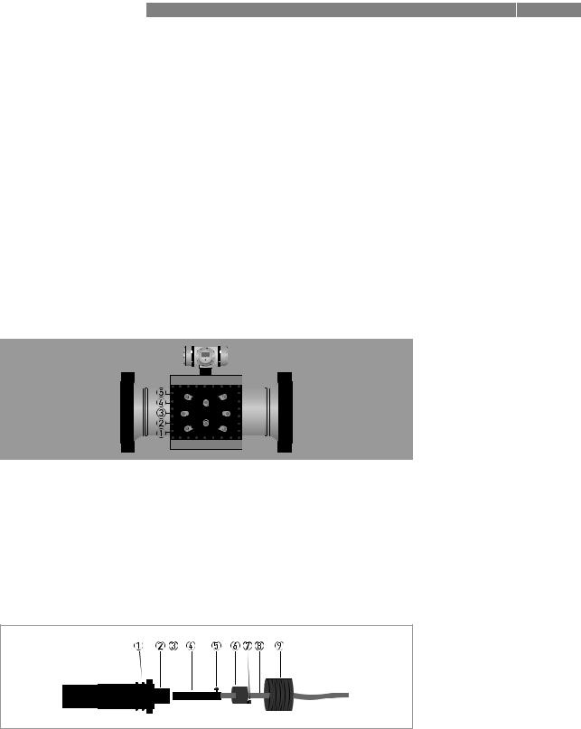
Figure 2-2: Location of sensors and electronic unit
2.2.1 Transducers
Acoustic signals are transmitted and received by means of ultrasonic transducers. The active part of an ultrasonic transducer is a small disk of piëzo electric ceramic in the front of the transducer. It is packaged (sealed) in a construction of metal parts and high grade epoxy or inside a titanium housing. The front side of the transducer is exposed to the gas to be measured, this results in the best efficiency for transmitting and receiving ultrasound.
Overview installation of transducer
Figure 2-3: Sensor assembly
1Double O-ring
2Slot in the socket
3Ex-d socket
4Ex-d plug
5Alignment pin
6Cap
7Securing screw M2
8Coaxial wire
9Transducer nut
12 |
www.krohne.com |
04/2013 - 4002643502 - MA ALTOSONIC V12 R02 en |
|
|
DEVICE DESCRIPTION 2 |
|
ALTOSONIC V12 |
|
|
|
|
DANGER!
The transducers have an Ex-d socket (socket, 3) that connects to an Ex-d plug 4 which terminates a coaxial wire 8.
An alignment pin 5 on the connector engages with a slot in the Ex-d socket 2, this ensures that the transducer is connected with the correct polarity. The cap 6, screwed on the Ex-d socket, fastens the connector, a small securing screw (M2) 7 secures this cap. The transducers are fastened in the meter body using a transducer nut with a hole in the centre 9. A double O-ring 1 seals the pressure inside the piping effectively from the outside world.
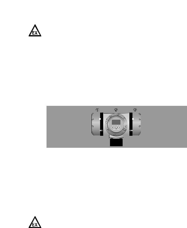
2.2.2 The electronic unit
The housing consists of three compartments. Each compartment has a removable cover that gives access to the inside, in order to connect external wiring or to install or to replace components.
Figure 2-4: Converter housing
1Power supply / RS485 compartment / Optional diagnostics board
2Electronics compartment
3Connection compartment
Connection compartment
The compartment on the right side is the connection compartment, which contains only a block with screw terminals. Signal wires from and to the electronics compartment are connected to this terminal block. Wiring to other (external/auxiliary) equipment can be connected to the screw terminals in this compartment.
Cables can enter this compartment through cable glands installed in either one of three threaded holes M20x1.5.
DANGER!
Unused holes must be closed with Ex d approved blind stops.
Power supply / RS485 compartment
The compartment on the left side is used to install the power converter. This board also includes two serial data ports (RS485). As an option an additional diagnostics processor board can be installed. Wiring to external equipment or to a power source is attached to connectors with screw terminals. These connectors engage directly with matching parts on the printed cicuit boards.
Cables can enter this compartment through cable glands installed in either one of three threaded holes M20x1.5.
04/2013 - 4002643502 - MA ALTOSONIC V12 R02 en |
www.krohne.com |
13 |

2 DEVICE DESCRIPTION |
ALTOSONIC V12 |
|
Electronics compartment
The compartment on the front has a cover with a glass window. It contains a frame with a number of printed circuit boards. The boards have the following functions:
•Frequency and status output board
•Processor boards
•Sensor driver board
•Display module (connected tot the front side of the frame, can be seen through the cover with the glass window)
2.3Software description
The ALTOSONIC V12 contains a powerful microprocessor that controls the functions and calculations it performs. The microprocessor executes program code consisting of several modules, according to the functions it has to perform. By means of a set of parameters the software can be configured to various sizes and models of flowmeters and according to specific requirements depending of applications or customers.
LEGAL NOTICE!
The parameters are stored in a configuration file. Configuration parameters are password protected in order to prevent unauthorized modification. Access in order to read, view and inspect parameter values is unrestricted.
Individual parameters are classified according to “roles” in order to define differentiated access rights. Each “role” is associated with a “typical” user or operator having specific responsibilities or duties. Users have to be registered with a user name and a password, when registered the role of the user is also defined, and by consequence also the access rights of that user.
The following roles have been defined, listed in according to the rank in the hierarchy.
Roles and authorisation
Developer |
restricted to KROHNE R&D employees. |
|
|
Factory |
restricted to KROHNE factory employees, to implement factory settings in the |
|
meter. |
|
|
Service |
restricted to authorized service personnel, to the discretion of KROHNE. |
|
|
Calibrator |
restricted to personnel acting on behalf of a legal calibration station. |
|
|
Supervisor |
restricted to personnel acting on behalf of the owner/operator of |
|
the meter (administrator function), to the discretion of the owner/operator of the |
|
meter. |
|
|
Operator |
restricted to personnel acting on behalf of the owner/ operator of the meter (for day |
|
to day operation), to the discretion of the owner/operator of the meter. |
|
|
Only a higher rank user can register a lower rank user. Users can have the same rank.
In addition to restrictions depending of the defined role of a user, a physical “overwrite disable” contact / jumper protects the configuration parameters. This disables any user from making modifications to parameters that would influence the measured flow or volume value. This prevents unintentional or unauthorized changes to the parameters and possibly invalidation of the calibration.
14 |
www.krohne.com |
04/2013 - 4002643502 - MA ALTOSONIC V12 R02 en |

|
|
DEVICE DESCRIPTION 2 |
|
ALTOSONIC V12 |
|
|
|
|
Normally the meter is delivered with a set of parameters suitable for the application.
In case a modification of the configuration file is made, this is stored in its data logging memory. This information can be retrieved afterwards for auditing and verification purposes.
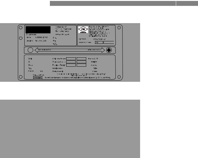
2.4 Nameplates
INFORMATION!
Look at the device nameplate to ensure that the device is delivered according to your order. Check for the correct supply voltage printed on the nameplate.
Figure 2-5: Example of a ATEX nameplate
Figure 2-6: Example of a IECEx nameplate
04/2013 - 4002643502 - MA ALTOSONIC V12 R02 en |
www.krohne.com |
15 |
2 DEVICE DESCRIPTION |
|
|
|
|
|
|
|
|
|
|
|
|
|
|
|
|
ALTOSONIC V12 |
|
||||||
|
|
|
|
|
|
|
|
|
|
|
|
|
|
|
|
|
|
|
|
|
|
|
|
|
|
|
|
|
|
|
|
|
|
|
|
|
|
|
|
|
|
|
|
|
|
|
|
|
|
|
|
|
|
|
|
|
|
|
|
|
|
|
|
|
|
|
|
|
|
|
|
|
|
|
|
|
|
|
|
|
|
|
|
|
|
|
|
|
|
|
|
|
|
|
|
|
|
|
|
|
|
|
|
|
|
|
|
|
|
|
|
|
|
|
|
|
|
|
|
|
|
|
|
|
|
|
|
|
|
|
|
|
|
|
|
|
|
|
|
|
|
|
|
|
|
|
|
|
|
|
|
|
|
|
|
|
|
|
|
|
|
|
|
|
|
|
|
|
|
|
|
|
|
|
|
|
|
|
|
|
|
|
|
|
|
|
|
|
|
|
|
|
|
|
|
|
|
|
|
|
|
|
|
|
|
|
|
|
|
|
|
|
|
|
|
|
|
|
|
|
|
|
|
|
|
|
|
|
|
|
|
|
|
|
|
|
|
|
|
|
|
|
|
|
|
|
|
|
|
|
|
|
|
|
|
|
|
|
|
|
|
|
|
|
|
|
|
|
|
|
|
|
|
|
|
|
|
|
|
|
|
|
|
|
|
|
|
|
|
|
|
|
|
|
|
|
|
|
|
|
|
|
|
|
|
|
|
|
|
|
|
|
|
|
|
|
|
|
|
|
|
|
|
|
|
|
|
|
|
|
|
|
|
|
|
|
|
|
|
|
|
|
|
|
|
|
|
|
|
|
|
|
|
|
|
|
|
|
|
|
|
|
|
|
|
|
|
|
|
|
|
|
|
|
|
|
|
|
|
|
|
|
|
|
|
|
|
|
|
|
|
|
|
|
|
|
|
|
|
|
|
|
|
|
|
|
|
|
|
|
|
|
|
|
|
|
|
|
|
|
|
|
|
|
|
|
|
|
|
|
|
|
|
|
|
|
|
|
|
|
|
|
|
|
|
|
|
|
|
|
|
|
|
|
|
|
|
|
|
|
|
|
|
|
|
|
|
|
|
|
|
|
|
|
|
|
|
|
|
|
|
|
|
|
|
|
|
|
|
|
|
|
|
|
|
|
|
|
|
|
|
|
|
|
|
|
|
|
|
|
|
|
|
|
|
|
|
|
|
|
|
|
|
|
|
|
|
|
|
|
|
|
|
|
|
|
|
|
|
|
|
|
|
|
|
|
|
|
|
Figure 2-7: Example of a FM nameplate
Figure 2-8: Example of a CSA nameplate
16 |
www.krohne.com |
04/2013 - 4002643502 - MA ALTOSONIC V12 R02 en |
|
|
INSTALLATION 3 |
|
ALTOSONIC V12 |
|
|
|
|
3.1 Notes on installation
CAUTION!
Inspect the packaging carefully for damages or signs of rough handling. Report damage to the carrier and to the local office of the manufacturer.
INFORMATION!
Do a check of the packing list to make sure that you have all the elements given in the order.
INFORMATION!
Look at the device nameplate to ensure that the device is delivered according to your order. Check for the correct supply voltage printed on the nameplate.
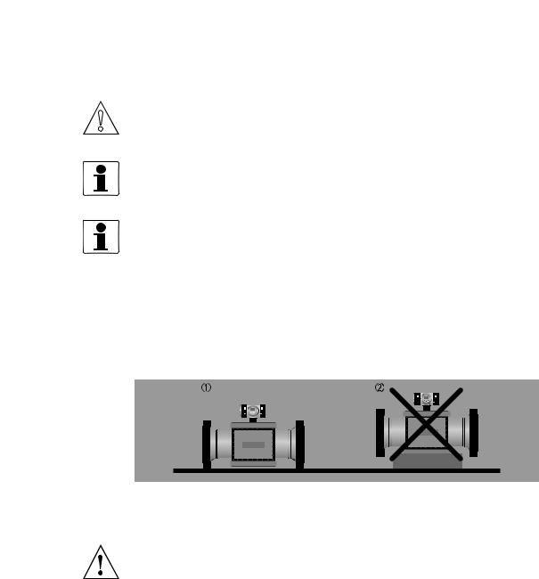
3.2 Storage
Correct storage position
Figure 3-1: Storage
1Correct position for all sizes
2Position not allowed for flowmeters > 12"
WARNING!
Make sure that the extensions on the bottom of the flanges are in good order to prevent the meter from rolling over. Otherwise take appropriate measures to prevent the meter from rolling over.
Storage conditions
Maintain the following storage conditions to prevent the equipment from corrosion or early failure:
•Humidity: <95 % RH (closed and heated storage area)
•Storage temperature: -40...+65º C / -40...+149º F
•Avoid direct solar radiation during long storage periods, store under a sunshade
How to prevent corrosion
Pay attention to the conservation of the inner pipe wall, especially for carbon steel meters. Typical applications such as measuring dry natural gas (sales quality) or natural gas with a corrosion inhibitor do not require an anti corrosion coating inside the meter tube. A coating can even be regarded as unwanted because it may wear off, which will have an impact (although minor) on the accuracy.
04/2013 - 4002643502 - MA ALTOSONIC V12 R02 en |
www.krohne.com |
17 |
3 INSTALLATION |
ALTOSONIC V12 |
|
However for storage and/or transportation additional protective measures are recommended. Depending on how long the protection should last one of several methods can be considered:
1.For a storage period of less than one year, the inner pipewall should be protected by a corrosion inhibitor such as Shell Ensys.
Do not apply the corrosion inhibitor on the acoustic transducers.
2.For a period of a year or longer, the pipewall should be protected by Tectyl or a similar product. Do not apply Tectyl on the acoustic transducers.
3.Independend of the storage period, the inner pipewall can be protected by an oxygen free environment. This can be created by mounting blind flanges, using a vacuum pump to remove the air and subsequently filling the meter with nitrogen. It is recommended to place some bags of silica gel inside the flowmeter. To protect against corrosion, the humidity should be less than 38% and/or oxygen should not be present. Special regulations may be applicable for transportation and storage of a pressurised flowmeter.
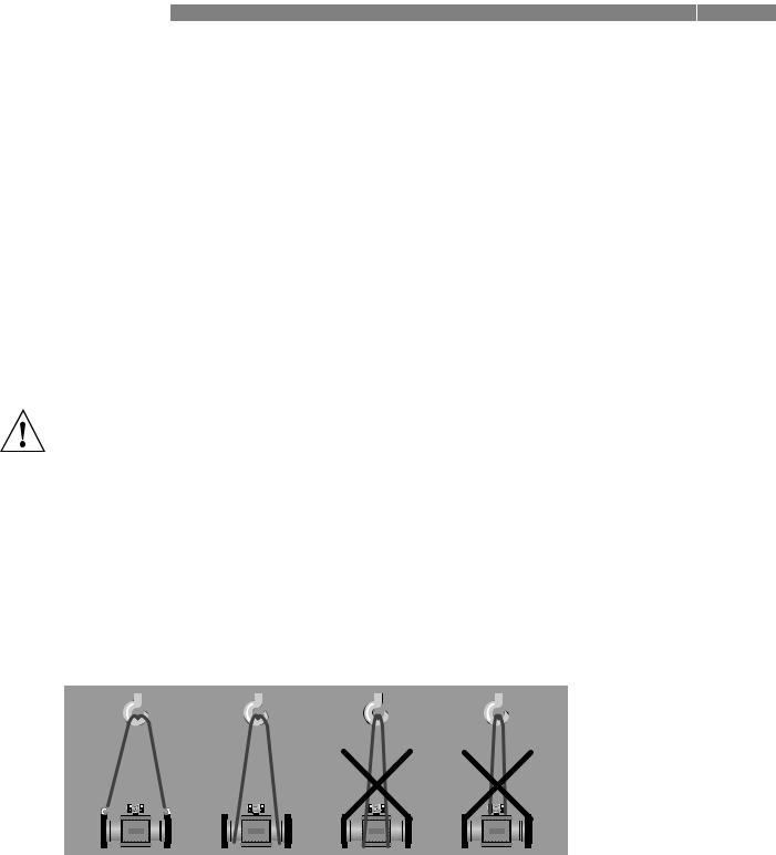
3.3Transport
WARNING!
• Even smaller size flowmeters have a considerable weight. Check the weight of your flowmeter in order to select suitable means for transportation and lifting.
•Use appropriate materials such as chains or hoisting straps that are in good condition.
•Use the eye bolts on the meter body to attach chains or straps to lift the meter (if not present: check condition of the threaded holes on the flanges and if okay screw eye bolts in the threaded holes).
•Never lift the meter using the converter housing to attach straps.
•In case a fork lift will be used make sure that the flowmeter is secured against rolling off the forks, or against straps sliding off the forks.
•Verify local safety regulations, directives and company procedures with respect to hoisting, rigging and transportation of (heavy) equipment.
18 |
www.krohne.com |
04/2013 - 4002643502 - MA ALTOSONIC V12 R02 en |
|
|
INSTALLATION 3 |
|
ALTOSONIC V12 |
|
|
|
|
3.4 Pre-installation requirements
INFORMATION!
The equipment is designed for safe operation under conditions according to the following classifications:
•Pollution degree 2: this means that normally only nonconductive (dry) pollution will occur. Temporary conductivity caused by condensation can occur.
•Protection class I: this means the equipment must be earthed.
•Humidity: <95% RH
•Ambient temperature: -40...+65°C / -40...+149°F
•Suitable for indoor and outdoor use.
•IP66 / NEMA 4X classification.
CAUTION!
The flowmeter should be protected from corrosive chemicals or gases and dust or particles accumulation.
CAUTION!
Do not intend to perform a hydrostatic test of the installed flowmeter.
The flowmeter has been hydrostatically tested during manufacturing (see reports) and must not be retested with the ultrasonic sensors installed. Water will protude in the sensor pockets and remain. This will create acoustic shortcuts and possibly cause the flowmeter to start operating in failure.
3.5 Installation
3.5.1 Mounting position
Install the ultrasonic gas flowmeter in horizontal position with the flow arrow indicator on the nameplate or on the meter body in the direction of the positive (forward) gas flow.
Make sure that the converter is on top of the flowmeter after the installation.
Check the weight of the meter. Typically the weight of the meter will be considerably more than the same length of pipe line.
To support the meter additional supports might be needed, preferably two, one on either side of the meter.
Always support the meter at its flanges, the weight of the meter shall never rest on the case around the transducers and the cabling.
If supports can not be placed under the meter flanges, supports may be placed under the mating flanges of the pipeline. If supports can only be placed under the pipeline sections upstream or downstream of the meter, these supports shall be as close as possible to the meter. In this case a calculation must be made to verify that the load on the pipeline will not exceed acceptable values.
The meter should be installed in the pipe line with gaskets, nuts and bolts according to the type and size of the flanges of the gas flowmeter. The flanges of the meter should match with the flanges of the pipeline where the meter should be installed.
Make sure that the gaskets do not protude into the flow as this can reduce the accuracy of the flowmeter.
04/2013 - 4002643502 - MA ALTOSONIC V12 R02 en |
www.krohne.com |
19 |
3 INSTALLATION |
ALTOSONIC V12 |
|
In order to install the gas flowmeter, the pipeline must have a slot of such length that the meter including the gaskets fits nicely in the slot. It should not be necessary to use excessive force to tighten the bolts in order to close the gaps on either side of the meter.
Nor should the slot be too small, implying the slot has to be widened by applying brute force to fit the meter and gaskets in the slot.
For tightening the bolts of the flanges, apply a lubricant as required, in accordance with the materials as used and applicable standards.
Tighten the bolts of the flanges with a torque according to the standards applicable to the flanges and materials used.
3.5.2 Pipe diameters and lengths
Make sure that the inner diameter of upstream and downstream pipes matches the specified connection diameter of the ultrasonic flowmeter within 1%. Contact KROHNE if the iner diameter deviates more than 1%.
3.5.3 Flow conditioners
Although the flowmeter is a highly accurate device, an additional flow conditioner can be installed upstream of the flowmeter in order to minimize measuring uncertainty, in particular when a strongly distorted flow velocity profile has to be expected, or when the available space for a metering run is critical. If a flow conditioner is used the total inlet length may be reduced to only 5 DN: having 2 DN upstream of the flow conditioner and 3 DN in between the flow conditioner and the flowmeter.
INFORMATION!
•Preferred model is the “perforated plate” type. A “pipe bundle” type of flow conditioner is not recommended.
•When a flow conditioner is included in the metering run, it is strongly advised to use the same flow conditioner and inlet pipe configuration during a flow (wet) calibration (see e.g. ISO17089 or AGA-9 for detailed requirements).
3.5.4Inlet and outlet for uni-directional use
Without flow conditioner (OIML R137 class 0.5)
Figure 3-2: Reguired straight lengths for inlet and outlet
1Inlet section: 10 DN
2Outlet section: 3 DN
20 |
www.krohne.com |
04/2013 - 4002643502 - MA ALTOSONIC V12 R02 en |
|
|
INSTALLATION 3 |
|
ALTOSONIC V12 |
|
|
|
|
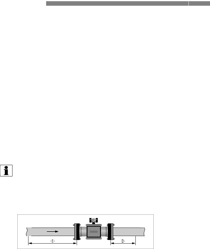
Without flow conditioner (AGA9, ISO 17089 and OIML R137 class 1)
Figure 3-3: Reguired straight lengths for inlet and outlet
1Inlet section: 5 DN
2Outlet section: 3 DN
With flow conditioner
Figure 3-4: Reguired straight lengths for inlet and outlet
1Inlet section before flow conditioner: 2 DN
2Flow conditioner (perforated plate)
3Inlet section after flow conditioner: 3 DN
4Outlet section: 3 DN
INFORMATION!
Contact KROHNE for recommendations on bi-directional use.
3.5.5 Control valves
CAUTION!
Under circumstances ultrasonic gas flowmeters can suffer from interference from noise generated by pressure control valves (PCV). In case the frequency spectrum of the PCV-noise extends in the range of the operation frequency of the ultrasonic transducers and the strength of the noise results in a signal to noise ratio smaller than the critical value, the ultrasonic flowmeter will not be able to operate. Consult the manufacturer for advice in case a PCV with high pressure cut will be operated close to the ultrasonic flowmeter.
04/2013 - 4002643502 - MA ALTOSONIC V12 R02 en |
www.krohne.com |
21 |
3 INSTALLATION |
|
|
|
|
|
|
|
|
|
|
ALTOSONIC V12 |
|
||||
3.5.6 P and T sensors |
|
|
|
|
|
|
|
|
|
|
|
|
||||
|
|
|
|
|
|
|
|
|
|
|
|
|
|
|
|
|
|
|
|
|
|
|
|
|
|
|
|
|
|
|
|
|
|
|
|
|
|
|
|
|
|
|
|
|
|
|
|
|
|
|
|
|
|
|
|
|
|
|
|
|
|
|
|
|
|
|
|
|
|
|
|
|
|
|
|
|
|
|
|
|
|
|
|
|
|
|
|
|
|
|
|
|
|
|
|
|
|
|
|
|
|
|
|
|
|
|
|
|
|
|
|
|
|
|
|
|
|
|
|
|
|
|
|
|
|
|
|
|
|
|
|
|
|
|
|
|
|
|
|
|
|
|
|
|
|
|
|
|
|
|
|
|
|
|
|
|
|
|
|
|
|
|
|
|
|
|
|
|
|
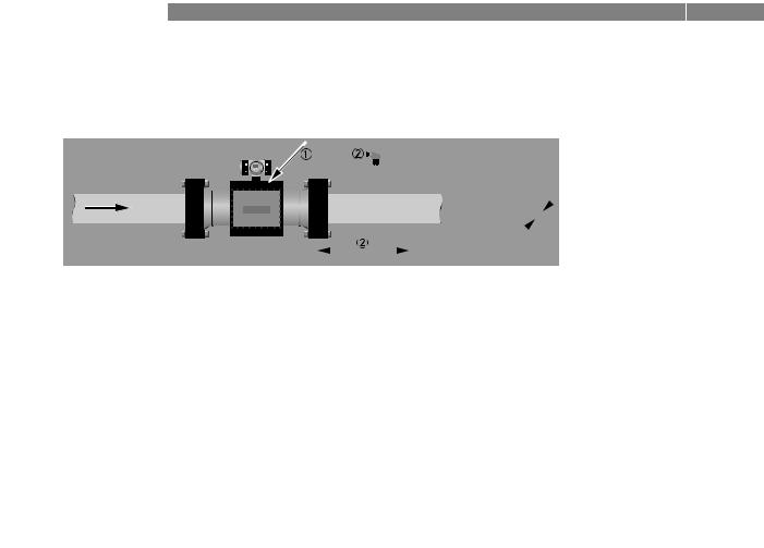
Figure 3-5: Location of pressure and temperature transmitters
1Install pressure transmitters on body of flowmeter at Pr point
2Install temperature transmitter at 2...5 DN downstream of flowmeter
3Install temperature transmitter under 45 degrees
4Install temperature transmitter with an insertion depth between 0.1 and 0.33 of nominal pipe diameter.
INFORMATION!
•See ISO 17089 for further details.
•Use a PT 100 element with thermowell and transmitter as temperature transmitter. Preferably use tapered thermowells to avoid vibrations.
•Connect the pressure transmitter to the Pr-point in the meter body using an intermediate isolation valve and/or valve manifold.
CAUTION!
Either use a suitable blind plug or blind flange (and sealing as required) to blind the pressure port, or a sense line should be connected in an appropriate way.
A sense line should be properly supported to avoid vibrations and to prevent the weight of the sense line to apply a load on the connection at the pressure port.
22 |
www.krohne.com |
04/2013 - 4002643502 - MA ALTOSONIC V12 R02 en |
|
|
INSTALLATION 3 |
|
ALTOSONIC V12 |
|
|
|
|
3.6 Temperatures
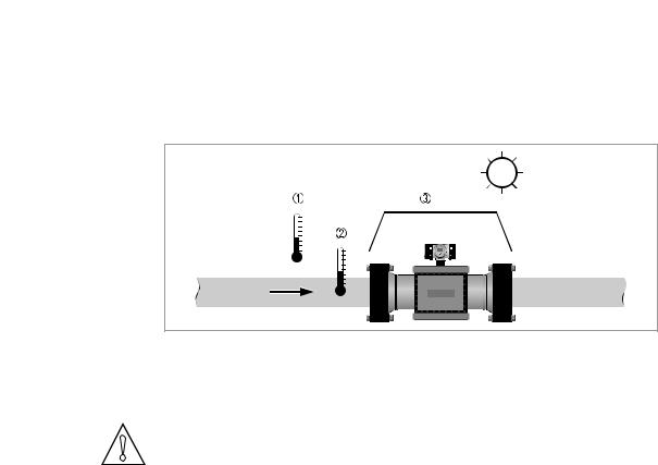
Figure 3-6: Temperatures
1Ambient temperature
2Process gas temperature
3Use a sun shade to protect the flowmeter against direct solar radiation.
CAUTION!
SUNSHADE
Direct solar radiation introduces temperature gradients in the metering section and must be avoided as much as possible. Use a sunshade or canopy over the flow, pressure and temperature transmitters for protection against direct exposure to sunshine. Another option is to thermally insulate the complete metering section including the transmitters.
For more detailed information about temperatures, refer to Technical data table on page 101.
04/2013 - 4002643502 - MA ALTOSONIC V12 R02 en |
www.krohne.com |
23 |
4 ELECTRICAL CONNECTIONS |
|
|
ALTOSONIC V12 |
|
|
|
|
|
4.1 Safety instructions
DANGER!
All work on the electrical connections may only be carried out with the power disconnected. Take note of the voltage data on the nameplate!
DANGER!
Observe the national regulations for electrical installations!
WARNING!
Observe without fail the local occupational health and safety regulations. Any work done on the electrical components of the measuring device may only be carried out by properly trained specialists.
INFORMATION!
Look at the device nameplate to ensure that the device is delivered according to your order. Check for the correct supply voltage printed on the nameplate.
DANGER!
For FM installations, cables must be used that are resistant to high temperatures.
For all other applications, cable must be used that are resistant to high temperatures if the process temperature is 65°C (149°F) or higher.
4.2 Opening and closing covers
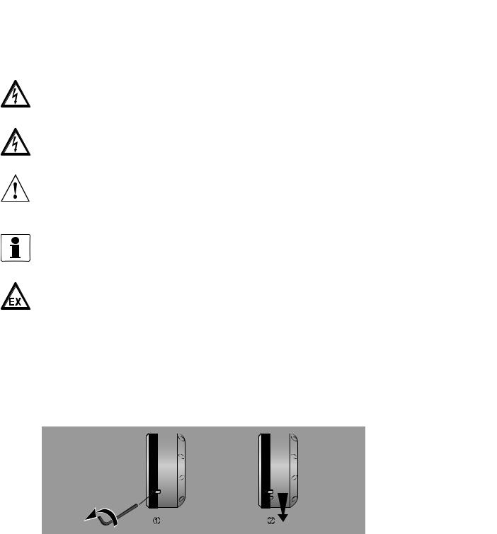
All covers are equipped with an interlocking device to prevent unauthorized or inadvertent opening and removal of the covers. Before a cover can be turned counter clockwise, the interlocking device has to be released as shown in the figure below.
Figure 4-1: Opening cover with interlocking device
1Loosen the hex screw with a 2.5 mm Allen key.
2Turn the cover counter clockwise to open the cover.
Closing the covers is done in the reverse order. Turn the cover until the little know on the cover is located under the interlocking device, then fasten the interlocking device.
24 |
www.krohne.com |
04/2013 - 4002643502 - MA ALTOSONIC V12 R02 en |
|
|
ELECTRICAL CONNECTIONS 4 |
|
ALTOSONIC V12 |
|
|
|
|
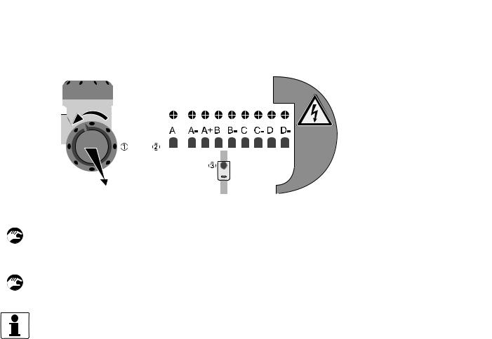
4.3 Digital I/O connections
WARNING!
1. In order to prevent unauthorized or inadvertent opening and removal of the covers, an interlocking device is provided for each cover. Before a cover can be rotated (counter clockwise) for opening, release this interlocking device with a 2.5 mm Allen key.
2.The foot of the converter housing provide an earthing point, this must be connected to the nearest safety earth conductor.
3.Only open the converter housing one minute after the power has been switched off and after it has been verified that there is no risk due to the presence of potentially explosive gas.
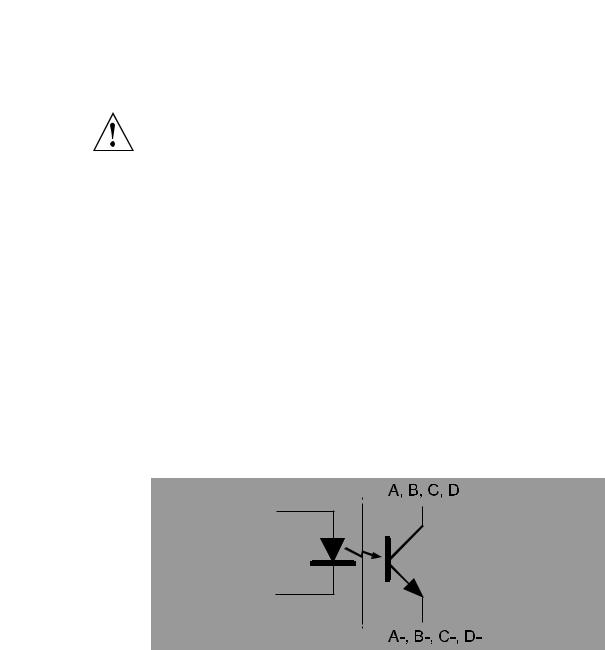
•The digital outputs are passive open collector outputs, galvanically isolated from each other and from the main circuit. To use these outputs an external voltage source and current limiting resistors must be used. (NEC class 2 power supply (max. 100 VA, 24 VDC, IEC 61010- 1, clause 6.3.1 and 6.3.2)
•For frequencies above 100 Hz, use shielded cables in order to reduce radiation from electrical interferences (EMC).
•Terminal A+ is not used.
Figure 4-2: Digital I/O as NPN transistor
04/2013 - 4002643502 - MA ALTOSONIC V12 R02 en |
www.krohne.com |
25 |
4 ELECTRICAL CONNECTIONS |
|
|
|
|
|
|
|
|
|
||
|
|
|
|
|
|
|
ALTOSONIC V12 |
|
|||
|
|
|
|
|
|
|
|
|
|
|
|
|
|
|
|
|
|
|
|
|
|
|
|
|
|
|
|
|
|
|
|
|
|
|
|
|
|
|
|
|
|
|
|
|
|
|
|
|
|
|
|
|
|
|
|
|
|
|
|
|
|
|
|
|
|
|
|
|
|
|
|
|
|
|
|
|
|
|
|
|
|
|
|
|
|
|
|
|
|
|
|
|
|
|
|
|
|
|
|
|
|
|
|
|
|
|
|
|
|
|
|
|
|
|
|
|
|
|
|
|
|
|
|
|
|
|
|
|
|
|
|
Figure 4-3: Terminal compartment for inputs and outputs in field housing
1 Open the housing cover.
2Push the prepared cable through the cable entry and connect the necessary conductors.
3Connect the shield if necessary.
• Close the cover of the terminal compartment.
• Close the housing cover.
INFORMATION!
Each time a housing cover is opened, the thread should be cleaned and greased. Use only resinfree and acid-free grease.
Ensure that the housing gasket is properly fitted, clean and undamaged.
4.3.1 Pulse and frequency output
Default the first digital I/O connection is set as a pulse/frequency output, having a frequency proportional to the volume flow rate (actual volume: under process conditions). It is possible to assign another variable to control this output (defined by means of parameter settings).
4.3.2 Status outputs
Default the next three digital I/O connections are defined as status outputs (Data not valid, Fail unreliable and Reverse flow). However the function of these outputs can be programmed to various alarms or status signals. One of the status outputs may be programmed to a second pulse output, having the same frequency as the first pulse output, however the phase difference can be set to either 0, 90, 180 or 270 degrees.
26 |
www.krohne.com |
04/2013 - 4002643502 - MA ALTOSONIC V12 R02 en |
|
|
ELECTRICAL CONNECTIONS 4 |
|
ALTOSONIC V12 |
|
|
|
|
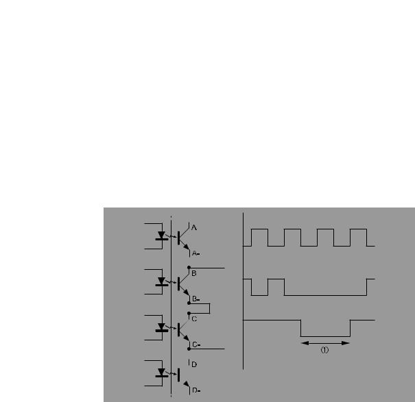
4.3.3 Emulation of a turbine meter
If the ultrasonic flowmeter should emulate a turbine meter, the following set up and settings can be implemented:
•A/A-: Frequency output related to the line flow
•B/B-: Frequency output inverted related to the line flow whereby this frequency output will stop operating if data valid alarm on status bit C/C- will occur.
Place the frequency output B/B in series with status bit C/C- as presented in the figure shown below.
Figure 4-4: Connection diagram for turbine emulation
1 Alarm
04/2013 - 4002643502 - MA ALTOSONIC V12 R02 en |
www.krohne.com |
27 |
4 ELECTRICAL CONNECTIONS |
|
|
ALTOSONIC V12 |
|
|
|
|
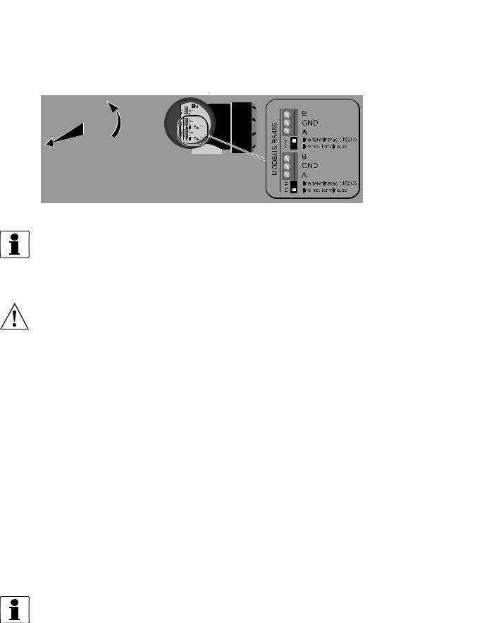
|
4.4 Serial data communication (RS 485)
Figure 4-5: Connection of serial data communication
INFORMATION!
For more information about Modbus, refer to Modbus protocol description and set-up on page 111.
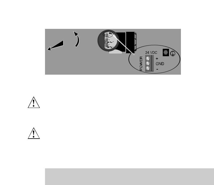
4.5 Power connection
WARNING!
• Use a 24 VDC power supply to power the flowmeter, which complies to NEC class 2 (max. 100 VA, 24 VDC ±10% , see also IEC 61010-1, clause 6.3.1 and 6.3.2). The maximum power consumption is 17 W. The power supply must be able to supply 3 A (needed during start-up).
•The protective earth conductor (1...4 mm2, AWG 17...AWG 11) of the power supply must be connected to the protective conductor clamp terminal size M5, which is press-fitted in the terminal compartment.
•Use a cable entry to lead the power supply cable to the electronics. The power delivered from the power converter inside the unit is limited to a maximum of 15 W according to the “foldback” principle (when the admissible internal power consumption is exceeded the delivered power is reduced to zero). Separately the current consumption is limited to appr. 1A. Requires typically 3 x 1.5 mm2 (AWG 15) conductors.
•Connection to a flow computer, a data acquisition system or process control system by means of digital output signals; requires as a maximum 4 pairs of wires of 0.75 mm2 (AWG 18) copper each.
•Connection by means of a RS 485 data line to a device for logging or monitoring data or running a software service tool for performing a function check or a service jobs; requires a shielded pair of two twisted conductors of 0.75 mm2 (AWG 18) copper each.
•Connection to a data acquisition system by means of digital signals; requires a shielded pair of two twisted conductors of 0.75 mm2 (AWG 18) copper each.
•Connection to safety / protective ground (earthing) ; requires insulated wire, minimum copper cross section area 4 mm2 (AWG 11).
INFORMATION!
•The protective conductor clamp or GND of the connector can be used for the shielding of the cable.
•The electronics is protected against connecting a power supply with the wrong polarity.
28 |
www.krohne.com |
04/2013 - 4002643502 - MA ALTOSONIC V12 R02 en |
|
|
ELECTRICAL CONNECTIONS 4 |
|
ALTOSONIC V12 |
|
|
|
|
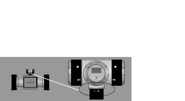
Figure 4-6: Location of power connector
4.6 Cabling
WARNING!
• Replace any unused cable gland by an Ex-d blind plug!
•The temperature rating of all cables must have a temperature rating of at least 65°C. In case the process design temperature exceeds 65°C, the cables must have a temperature rating at least as high as the maximum process design temperature.
WARNING!
In respect of the model of the cable glands used, the outer diameter of the cable must be between 6.5 and 14 mm. Unused cable glands must be replaced by Ex d approved blind stops.
We recommend to use screened cable with twisted pairs for connecting power, serial outputs and the status signals. The screen can be used to connect the ground terminal.
Length of power supply cable vs diameter
Length of cable between power supply and |
Required minimum copper cross section |
flowmeter |
|
[m] |
|
|
|
70 |
2 x 0.5 mm2 (AWG 20) |
100 |
2 x 0.75 mm2 (AWG 18) |
200 |
2 x 1.5 mm2 (AWG 15) |
400 |
2 x 4 mm2 (AWG 11) |
04/2013 - 4002643502 - MA ALTOSONIC V12 R02 en |
www.krohne.com |
29 |
4 ELECTRICAL CONNECTIONS |
|
|
ALTOSONIC V12 |
|
|
|
|
|
4.7 Grounding
There are two screw connection points (one M5 thread and one M4 thread) to attach a ground conductor. They can be used to connect the upstream and downstream piping to the flowmeter (Equipotential).
Figure 4-7: Location of grounding connectors
30 |
www.krohne.com |
04/2013 - 4002643502 - MA ALTOSONIC V12 R02 en |
 Loading...