

Instructions for Use, v 98.3
Audio + Video Standard
Surround
Preamp/Processor
Owner’s Reference
Audio + Video Standard
Surround Preamp/Processor
CONTENTS
Krell® Industries, Inc.
45 Connair Road
Orange, CT 06477-3650
TEL 203-799-9954
FAX 203-799-9796
E-MAIL krell @ krellonli ,ne.com
WEB SITE ~.krellonline.com
USA
INTRODUCTION
UNPACKING
PLACEMENT
FRONT PANEL
DESCRIPTION
BACK PANEL
DESCRIPTION
CONNECTING THE AUDIO + VIDEO
STANDARD TO YOUR SYSTEM
REMOTE CONTROL
DESCRIPTION
SYSTEM CONFIGURATION
OPERATION
SAVING, RECALLING, AND
CLEARING CONFIGURATION
SET-rINGS
3
3
4
5
9
12
13
18
26
29
998 by KRELL® Industries, Inc. All rights reserved
WARRANTY
RETURN AUTHORIZATION
PROCEDURE
SPECIFICATIONS
ILLUSTRATIONS
Figure 1 FRONT PANEL
Figure 2 BACK PANEL
Figure 3 REMOTE CONTROL
P/N 1960101900389
3O
31
Back Cover
Page
8
11
16
CE Marking
Unpacking
This ’product complies with the EMC directive (89/336/EEC) and the low-voltage directive (73/23/EEC).
¯
Introducbon
®
Thank you for your purchase of the Krell
Audio + Video Standard. To obtain the best
performance from your Audio + Video
Standard surround preamp/processor, pay
careful attention to its placement, installa-
tion, and operation. A thorough understand-
ing of these details will help insure satisfac-
tory operation andlong life for the Audio +
Video Standard and related’ system compo-
nents.
THERE ARE NO USER-SERVICEABLE
PARTS INSIDE ANY KRELL® PRODUCT.
Please contact your authorized dealer,
distributor, or KrelP, if you have any ques-
tions not addressed in this reference
manual.
~
1. Open the box and remove the top layer of
foam. You will see these items:
1 Audio + Video Standard
1 AC power cord
1 Audio + Video remote control
4 AAA batteries
1 T-10 Torx wrench
1 packet containing an introductory
letter from Dan D’Agostino, C.E.O.,
the Owner’s Reference, and the
Warranty Registration Card
Note
If any of these items are not included, please
contact your authorized Krell® dealer or dis-
tributor immediately for assistance.
Carefully remove the unit and acces-
sories from the box. Remove the protec-
tive plastic wrap from the unit.
Note
Save all packing materials, ff you must ship
your Audio + Video Standard in the future,
repack the unit in its original packaging to
prevent transit damage.
KRELL® Audio + Video Standard English Page 3 of 32
Placement
WARNING
The surround preamp/processor must not
be located where it could be exposed to dripping or splashin~luids.
IMPORTANT
The ventilation grids and cooling fan on the
top of the Audio + Video Standard need to
be unobstructed at all times during operation. Do not place flammable material on
top of or beneath the Audio + Video
Standard. For installations inside cabinet04,
make sure the Audio ÷ Video Standard has
adequate air circulation. Contact your dealer,
distributor or Krell~ for further information.
Before you install the Audio + Video
Standard. into your system, review the
following guidelines to choose the opti-
mum location for placement. This will
help ensure a clean, trouble-free installa-
tion. For the dimensions of the Audio +
Video Standard, see Specifications on
back cover.
Place the Audio + Video Standard surround
preamp/processor on a firm level surface
away from dirt or moisture. A minimum spacing of three inches must exist between the
Audio + Video Standard and surrounding
components to ensure proper ventilation.
AC POWER GUIDELINES
WARNING
Do not remove or bypass the ground pin
on the end of the AC cord. This may cause
RFI (radio frequency interference) to
induced into your playback system.
The Audio + Video Standard has superb regulation and does not require a dedicated AC
circuit. Avoid connections through extension
cords or multiple AC adapters. High quality,
15 ampere, grounded AC strips are accept-
able. High quality AC line conditioners or filters may be used if they are grounded.
Page 4 of 32 English KRELL® Audio + Video Standard
Front Panel
Description
See Figure 1 on page 8
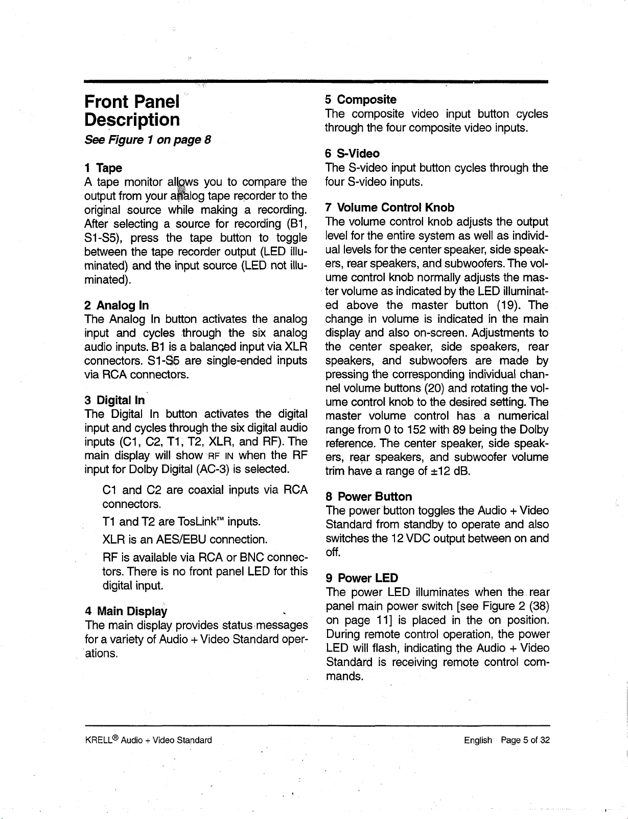
1 Tape
A tape monitor al!~ws you to compare the
output from your a~log tape recorder to the
original source while making a recording.
After selecting a source for recording (B1,
$1-$5), press the tape button to toggle
between the tape recorder output (LED illu-
minated) and the input source (LED not illuminated).
2 Analog In
The Analog In button activates the analog
input and cycles .through the six analog
audio inputs. B1 is a balanced input via XLR
connectors. $1-$5 are single-ended inputs
via RCA connectors.
3 Digital In
The Digital In button activates the digital
input and cycles through the six digital audio
inputs (C1, C2, T1, T2, XLR, and RF). The
main display will show RF IN when the RF
input for Dolby Digital (AC-3) is selected.
5 Composite
The composite video input button cycles
through the four composite video inputs.
6 S-Video
The S-video input button cycles through the
four S-video inputs.
7 Volume Control Knob
The volume control knob adjusts the output
level for the entire system as well as individual levels for the center speaker, side speak-
ers, rear speakers, and subwoofers. The volume control knob normally adjusts the mas-
. ter volume as indicated by the LED illuminat-
ed above the master button (19). The
change in volume is indicated in the main
display and also on-screen. Adjustments to
the center speaker, side speakers, rear
speakers, and subwoofers are made by
pressing the corresponding individual chan-
nel volume buttons (20) and rotating the volume control knob to the desired setting. The
master volume control has a numerical
range from 0 to 152 with 89 being the Dolby
reference. The center speaker, side speakers, rear speakers, and subwoofer volume
trim have a range of __.12 dB.
C1 and C2 are coaxial inputs via RCA
connectors.
T1 and T2 are TosLink
XLR is an AES/EBU connection.
RF is available via RCA or BNC connectors. There is no front panel LED for this
digital input.
4 Main Display ,
The main display provides status.messages
for a variety of Audio + Video Standard oper-
ations.
KNELL® Audio + Video Standard English Page 5 of 32
TM
inputs.
8 Power Button
The powerbutton toggles the Audio + Video
Standard from standby to operate and also
switches the 12 VDC output between on and
off.
9 Power LED
The power LED illuminates when the. rear
panel main power switch [see Figure 2 (38)
on page 11] is placed in the on position.
During remote control operation, the power
LED will flash, indicating the Audio + Video
Standard is receiving remote control commands.
10-16 Audio Mode Buttons
The five buttons (10, 13, 14, 15, and 16)
select one of the Audio + Video Standard’s
audio modes.
The Audio + Vid~.o Standard automatically
selects which di~al decodingformat to use,
based on the input signal it receives.
When a silent digital signal .is present, the
Audio+Video Standard will automatically
mute its output until program material
resumes and the Audio+Video Standard
identifies the correct processing mode. This
occurs while changing laser, DVD or com-
pact discs, and between tracks on a cd.
Mute protects your syste ,m by preventing the
Audio + Video ~Standard from playing back
digital data in an incorrect format. If the Audio
+ Video Standard is going to be used as a
digital to analog converter for music playback, this muting may seem awkward
because the beginning of each track may be
affected. You can change the format auto-
sensing to eliminate this muting, if you wish.
To do so, switch the unit into standby. Press
the DTS button (13) on the front panel and
switch the Audio+Video Standard out of
standby to power on (operate). This will dis-
able the automatic muting feature of the
Audio+Video Standard and will alter the way
in which the automatic format sensing oper-
ates. For best results, select DTS prior to listening to any DTS encoded material and be
careful to select the proper format for each
piece of softWare played through the. digital
inputs.
To re-engage the automatic muting feature,
switch the Audio+Video Standard into standby and toggle the main power switch (38)
the rear panel to the off position. When. you
restart your Audio + Video Standard, the
automatic muting feature will be active. Be
sure to turn all amplifiers off when switching
the main power switch on and off.
10 Dolby Digital engages Dolby Digital
(AC-3) processing for use with Dolby
Digital (AC-3) encoded source material.
The Audio + Video Standard automati-
cally switches to Dolby Digital (AC-3) processing upon receiving a Dolby Digital
(AC-3) encoded signal. No user interven-
tion is required after the appropriate digital input is selected and connected.
Dolby Pro Logic engages Dolby Pro
Logic circuitry for use with all Dolby sur-
round processing encoded material. This
includes laser discs, videotapes, television broadcasts, and compact discs.
11 The Dolby Digital LED is lit and the
Dolby Pro Logic LED (12) is not lit when
the Audio+ Video Standard is in the
Dolby Digital (AC-3) decoding mode.
When both the Dolby Digital LED and the
Dolby Pro Logic LED are lit, the Audio +
Video Standard is decoding a Dolby
Digital (AC-3) encoded Dolby Pro Logic
signal.
12 The Dolby Pro Logic LED is lit and
the Dolby Digital LED (11) is not lit when
the Audio+ Video Standard is in the
Dolby Pro Logic decoding, mode. When
both the Dolby Digital LED and the Dolby
Pro Logic LED are lit, the Audio + Video
Standard is decoding a Dolby Digital
(AC-3).encoded Dolby Pro Logic Signal.
13 DTS engages DTS digital surround
processing for use with DTS encoded
source material. The Audio + Video
$tandard automatically switches to DTS
processing upon receiving a DTS signal.
No user intervention is required after the
Page 6 of 32 English
KRELL® Audio + Video Standard
appropriate digital input is selected and
connected.
TM
14 Music engages Krell Music Surround
circuitry for use with stereo recordings.
15 Mono is for use with monophonic
recordings. This provides monaural out-
put from the ~nter speaker and sub-
woofer(s) only.~lf the system does not
include a center speaker, the monaural
signal is split between theleft and right
speakers.
16 Preamp disengages all surround
processing circuitry for use with stereo
recordings. When fed an analog source,
the Audio + Video Standard functions as
a pure Class Ai~ high resolution, analog
preamplifier. For digita, I sources, the
Audio + Vide£ Standard employs 24-bit,
custom KrelP-written, digital-to-analog
conversion software before being sent to
the analog preamplifier stage.
17 Recall Button
This button saves and recalls system config-
uration settings..
ume adjustment is indicated in the main
display and also on-screen.
20 Individual Channel
VolumeTrim
When the LED above any of these buttons is illuminated, the volume control
knob (7) changes the level of the selected channel. These new changes will
clear when a new input mode is selected.
The volume control knob reverts back to
controlling the default level, Master, after
four seconds of inactivity.
21 Balance Button
(Preamp mode only)
When the LEE) above this button is illu-
minated, the volume control knob (7)
affects the left-to-right balance of the sys-
tem. The center position is indicated by
CNTR in the main display. Balance may be
adjusted in 1 dB increments up to 9 dB.
The next adjustment mutes either channel, indicated by ROFF or LOFF for the right
channel and left channel respectively.
The on-screen representation for bal-
ance is graphical:
18 Infrared Sensor
L ......... : ......... R
The infrared sensor receives commands
from the Audio + Video Standard remote
control. For proper remote control operation,
make sure the infrared sensor is clear of any
obstructions.
19-21 Volume Control Buttons
The following six buttons select one of the
Audio + Video Standard’s volume chant~els:
The center position is indicated by two
vertical dots, Each dB of adjustment is
represented by one individual dot.
Moving the cursor so that it covers the L
indicates a completely muted right channel. Conversely, positioning the cursor so
that it covers the R indicates a complete-
ly muted-left channel. The volume control
knob (7) reverts back to controlling the
19 Master Volume Button
When the LED above this button is illu-
default level, Master, after four seconds
of inactivity.
minated, the volume control knob (7)
affects the entire system equally. The vol-
KRELL® Audio + Video Standard English Page 7 of 32
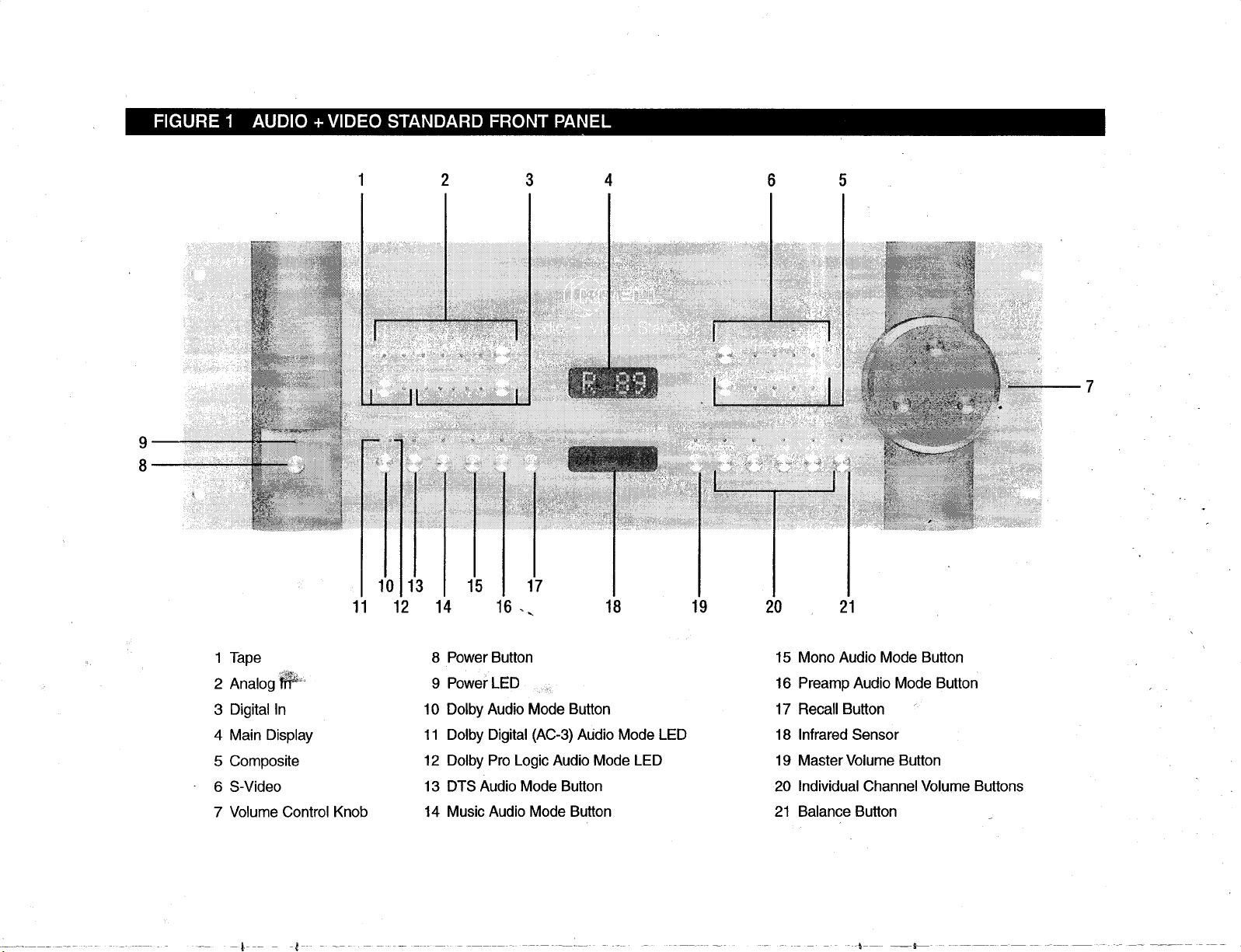
FIGURE 1 AUDIO + VIDEO STANDARD FRONT PANEL
2 3
9
11
10 13
12
15 17
14 16 .. 18 19
4 6 5
2O 21
1 Tape
Analog ~’~
2
Digital In
3
4 Main Display
Composite
5
6 S-Video
7 Volume Control Knob
8 Power Button
9 Powe~ LED
10 Dolby Audio Mode Button
11 Dolby Digital (AC-3) Audio Mode LED
12 Dolby Pro Logic Audio Mode LED
13 DTS Audio Mode Button
14 Music Audio Mode Button
15 Mono Audio Mode Button
Preamp Audio Mode Button
16
17 Recall Button
18 Infrared Sensor
19 Master Volume Button
20 Individual Channel Volume Buttons
21 Balance Button
Back Panel
Description
Connections are via RCA or BNC coaxial
digital cable.
See Figure 2 on page 11
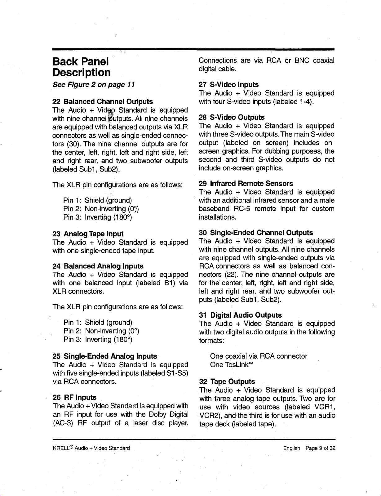
22 Balanced Channel Outputs
The Audio + Vid~p Standard is equipped
with nine channel ~utputs. All nine channels
are equipped with balanced outputs via XLR
connectors as well as single-ended connec-
tors (30). The nine channel outputs are for
the center, left, right, left and right side, left
and right rear, and two subwoofer outputs
(labeled Sub1, Sub2).
The XLR pin configurations are as follows:
1" Shield (g~round)
Pin
°,)
Pin2: Non-inverting (0,
°
3: InvertiNg (180
)
Pin
23 Analog Tape Input
The Audio + Video Standard is equipped
with one single-ended tape input.
24 Balanced Analog Inputs
The Audio + Video Standard is equipped
with one balanced input (labeled B1) via
XLR connectors.
The XLR pin configurations are as follows:
Pin 1: Shield (ground)
°)
Pin2: Non-inverting (0
°
3: Inverting (180
)
Pin
27 S-Video Inputs
The Audio + Video Standard is equipped
with four S-video inputs (labeled 1-4).
28 S-Video Outputs
The Audio + Video Standard is equipped
with three S-video outputs. The main S-video
output (labeled on screen) includes onscreen graphics. For dubbing purposes, the
second and third S-video outputs do not
include on-screen graphics.
29 Infrared Remote Sensors
The Audio + Video Standard is equipped
with an additional infrared sensor and a male
baseband RC-5 remote input for custom
installations.
30 Single-Ended Channel Outputs
The Audio + Video Standard is equipped
with nine channel outputs. All nine channels
are equipped with single-ended outputs via
RCA connectors as well as balanced con-
nectors (22). The nine channel outputs are
for the center, left, right, left and right side,
left and right rear, and two subwoofer outputs (labeled Sub1, Sub2).
31 Digital Audio Outputs
The Audio + Video Standard is equipped
with two digital audio outputs in the following
formats:
25 Single-Ended Analog Inputs
The Audio + Video Standard is equipped
with five single-ended in puts (labeled S’1-$5)
via RCA connectors.
26 RF Inputs
The Audio + Video Standard is equipped with
an RF input for use with the Dolby Digital
(AC-3) RF output of a laser disc player.
KRELL® Audio + Video Standard English Page 9 of 32
One coaxial via RCA connector
TM
One TosLink
32 Tape Outputs
The Audio + Video Standard is equipped
with three analog tape outputs. Two are for
use with video sources (labeled VCR1,
VCR2), and.the third is for use with an audio
tape deck (labeled tape).
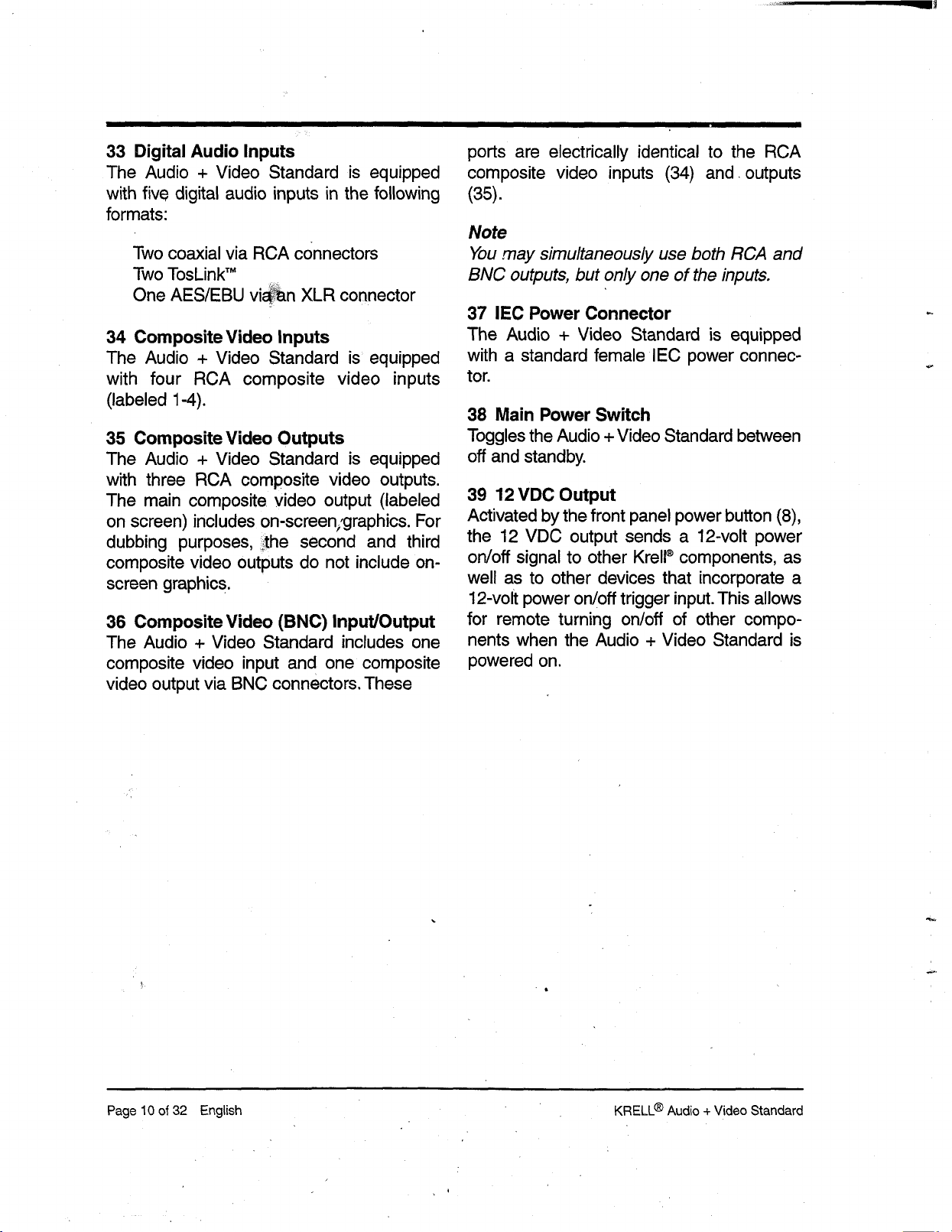
33 Digital Audio Inputs
The Audio + Video Standard is equipped
with five digital audio inputs in the following
formats:
Two coaxial via RCA connectors
TM
Two TosLink
One AES/EBU vixen XLR connector
34 Composite Video Inputs
The Audio + Video Standard is equipped
with four RCA composite video inputs
(labeled 1-4).
35 Composite Video Outputs
The Audio + Video Standard is equipped
with three RCA composite video outputs.
The main composite video output (labeled
on screen) includes on-screen;graphics. For
dubbing purposes, ~the second and third
composite video outputs do not include on-
screen graphics.
36 Composite Video (BNC) Input/Output
The Audio + Video Standard includes one
composite video input and one composite
video output via BNC connectors. These
ports are electrically identical to the RCA
composite video inputs (34) and, outputs
(35).
Note
You may simultaneously use both RCA and
BNC outputs, but only one of the inputs.
37 IEC Power Connector
The Audio + Video Standard is equipped
with a standard female IEC power connector.
38 Main Power Switch
Toggles the Audio + Video Standard between
off and standby.
39 12 VDC Output
Activated by the front panel power button (8),
the 12 VDC output sends a 12-volt power
on/off signal to other Krell® components, as
well as to other devices that incorporate a
12-volt power on/off trigger input. This allows
for remote turning on/off of other compo-
nents when the Audio + Video Standard is
dowered on.
Page 10 of 32 English KRELL® Audio + Video Standard

FIGURE 2 AUDIO +VIDEO STANDARD BACK PANEL
22 30
22
23 24 25 26 27 28 36 39 29
32 31 33 34 35
Balanced Ch~l Outputs
22
23 Analog Tape ~nput
24 Balanced Analog Inputs
25 Single-Ended Analog Inputs
26 Dolby Digital Inputs
27 S-Video Inputs
S-Vid oO uts
29 In~rared Remote Sensors
Single-Ended Channel Outputs
30
31 Digital Audio Outputs
Tape Outputs
32
33 Digital Audio Inputs
34 Composite Video Inputs
Composite Video Outputs
35
36 Cdmposite Video (BNC) Input/Output
37 IEC Power Connector
38 Main Power Switch
39 12 VDC Output

Connecting the
Audio + Video Standard
to Your System
WARNING
When making conn~ions to thi.s compo-
nent or any other, make sure the power
amplifier is off and the preamplifier is in the
mute or stand-by mode. Make sure all
cable terminations are of the highest quality, free from frayed ends, shorts, or cold
solder joints.
Connect the video outputs of your video
sources to the video inputs on the Audio
+ Video Standard.
The Audio + Video Standard is equipped
with four S-video inputs and four composite
video inputs. S-video cables transmit the
color and luminance components of the
video signal separately. This separation is
performed by the comb filter within the
source unit. If the source unit’s comb filter is
superior to the one within the video monitor,
S-video connections should be used.
Otherwise, a composite video connection
should be used.
For analog audio sources, connect the
left and right outputs of your source com-
ponents to the inputs on ,the Audio +
Video Standard. The Addio + Video
Standard is equipped with six single-
ended analog audio inputs ($1-$5 and
tape) via RCA connectors and one bal-
anced analog audio input (B1) via
XLR connector.
2. For digital audio sources, connect the
digital audio output of your source com-
ponents to the digital inputs on the Audio +
Video Standard. The Audio + Video
Standard is equipped with five digital
inputs: two coaxial inputs via RCA con-
nectors, two TosLink
tions, and one AES/EBU via an XLR
connector. For Dolby Digital (AC-3) sur-
round processing, connect the RF output
of a laser disc player to one of the RF
inputs.
TM
optical connec-
Notes
S-video cables should not be used for
lengths greater than 20 feet, for optimum
performance.
The Audio + Video Standard does not con-
vert video signal formats, Le., an S-video
input signal is output as an S-video signal
The same condition holds true for a com-
posite video signal
The Audio + Video Standard is equipped
with three S-video outputs and three com-
posite video outputs. The main S-video output (28) and composite video output (35)
include on-screen graphics. The composite
video 1 output also has a parallel BNC con-
nector. For dubbing purposes, the second
and third video outputs do not include on-
screen graphics. These outputs may be connected to the video inputs of your video
recorders or to:additional video monitors.
Note
For source units that are equipped with both
digital and analog audio outputs, higher per-
formance will generally result when connecting source units to the Audio + Video Standard
using a digital audio output.
Page 12 of 32 English KRELL® Audio + Video Standard
Connect the outputs of the Audio + Video
Standard to the input(s) of your power
amplifier(s).

Connect the outputs of the Audio + Video
Standard to the input(s) of your power
amplifier(s).
The Audio + Video Standard has balanced
outputs via XLR connectors and single-
ended outputs ~,, RCA connectors. Both
outputs are act~e at all times, allowing
simultaneous connection to separate amplifiers. Only one of these output formats
should be connected to a single amplifier.
Remote Control
Description
See Figure 3 on page 16
40 Analog Audio Input Buttons
These buttons select the analog audio
source. B1 is a balanced input via XLR con-.
nectors while $1-$5 are single ended inputs
via RCA connectors. The tape button allows
access to an analog tape recorder.
Note
When connecting inputs or outputs to the
Audio + Video Standard, remember that the
balanced connections will have 6 dB more
gain than the single-ended connections. If
level matching becomes difficult in your
installation, keep this spe~’fication in mind.
Plug the AC cord into the receptacle on
5.
the back of the Audio + Video Standard.
Plug the remaining end into the AC wall
receptacle. Toggle the main power
switch (38) to the up position. The red
power LED (9) will illuminate, and the
main display (4) will show AC-3 for three
seconds. The Audio + Video Standard is
now ready for operation.
Press either the front panel power button
(8) or the remote control power button
[see Figure 3 (44) on page 15]. The word
WAIT will appear in the main display and
the initializing message will appear on-
screen. To configure the Audio + Video
Standard for operation, see System
Configuration on page 18.
41 Digital Audio Input Buttons
These buttons select the digital audio
source. C1 and C2 are coaxial inputs via
TM
RCA connectors, T1 and T2 are TosLink
inputs, XLR is an AES/EBU connection, and
RF is available via RCA or BNC connectors.
42 Processing Mode Buttons
The following six buttons select one of the
Audio + Video Standard’s processing
modes. FCN, the function button, is reserved
for future use.
The Audio + Video Standard automatically
selects which digital decoding format to use,
based on the input signal it receives.
When a silent digital signal is present, the
Audio +Video Standard will automatically
mute its output until program material
resumes and the Audio +Video Standard
identifies the correct processing mode. This
occurs while changing laser, DVD or com-
pact discs, and between tracks on a cd.
Mute protects your system by preventing the
Audio + Video Standard from playing back
digital data in an incorrect format. If the
Audio + Video Standard is going to be used
as-a digital to analog converter for music
playback, this muting may seem awkward
because the beginning of each track may be
affected. You can change the format auto-
KRELL® Audio + Video Standard English Page 13 of 32

sensing to eliminate this muting, if you wish.
To do so, switch the unit into standby. Press
the DTS button (13) on the front panel and
switch the Audio+Video Standard out of
standby to power on (operate). This will disable the automatic muting feature of the
Audio+Video Stan,~ard and will alter the way
in which the automatic format,sensing oper-
ates. For best results, select DTS prior to listening to any DTS encoded material and be
careful to select the proper format for each
piece of software played through the digital
inputs.
To re-engage the automatic muting feature,
switch the Audio+Video Standard into stand-
by and toggle the main power switch (38)
the rear panel to the off position. When you
restart your Audio + Video Standard, the
automatic mutin~ feature will be active. Be
sure to turn all amplifiers off when switching
the main power switch on and off.
appropriate digital input is selected and
connected.
T"
Music engages Krell Music Surround
circuitry for use with stereo recordings.
Mono is for use with monophonic
recordings. This provides monaural output from the center speaker and sub-
woofer(s) only. If the system does not
include a center speaker, the monaural
signal is split between the left and right
speakers.
Prearnp disengages all surround pro-
cessing circuitry for use with stereo
recordings. When fed an analog source,
the Audio + Video Standard functions as
a pure Class A, high resolution, analog
preamplifier. For digital sources, the
Audio + Video Standard employs 24-bit,
custom Krell®-written, digital-to-analog
conversion software before being sent to
the analog preamplifier stage.
Dolby Digital engages Dolby Digital
(AC-3) processing for use with Dolby
Digital (AC-3) encoded source material.
The Audio + Video’ Standard automati-
cally switches to Dolby Digital (AC-3) processing upon receiving a Dolby Digital
(AC-3) encoded signal. No user interven-
tion is required after the appropriate digital input is selected and connected.
Dolby Pro Logic engages Dolby Pro
Logic circuitry for use with all Dolby surround processing encoded material. This
includes laser discs, videotapes, television broadcasts, and compact discs.
DTS engages DTS digital surround processing for use with DTS encoded
source material. The Audio + Video
Standard automatically switches to DTS
processing upon receiving a DTS signal.
No user intervention is required after the
43 Levels Buttons
These buttons select one of the Audio +
Video Standard’s volume channels.
Master selects all channels for systemwide volume control.
Balance (Preamp Mode Only) adjusts
the left-to-right balance of the system.
Mute interrupts any audio signal to
source equipment.
44 Power Button
The power button toggles the Audio + Video
Standard from standby to operate.
45 Vol Down/Vol Up.Buttons
The-vol down and vol up buttons control the
volume for either the entire system or for an
Page 14 of 32 English KRELL® Audio + Video Standard

individual channel, a~: selected by the levels
buttons (4,3).
46 Amplifier Buttons
®
The power and meter buttons operate Krell
amplifiers.
47 System Button~
These buttons select a preassigned video
input. Once a video in put is assigned, it may
then be linked to a specific audio input and
surround mode. For details on this assigning
and linking procedure, see Direct Access
Remote Control System Programming on
page 24.
48 Video Buttons
These buttons select the video source. CV1 CV4 are composite video inj~uts, and SV1-
SV4 are S-video in.puts.
49 Enter Button
This button inputs on-screen menu selections (functions only in the menu mode).
50 Scroll Buttons
These four buttons scroll on-screen menu
options, and also are used for volume con-
trol.
51 Menu Button
This button accesses, the on-screen menu
functions.
52 Previous Button
This button escapes or ends certain
on-
screen menu operations.
KRELL® Audio .- Video Standard English Page 15 of 32

FIGURE 3 AUDIO + VIDEO STANDARD REMOTE CONTROL
4O
41
42
46
49
50
52
44 43 45 47
40 Analog Audio input Buttons
41 Digital Audio Input Buttons
42 Processing Mode Buttons
43
Levels Buttons
Page 16 of 32 English
44 Power Button
Vol Down /Vol Up Buttons
45
46 Amplifier Buttons
47 System Buttons
48
48 Video Buttons
49 Enter Button
50 Scroll Buttons
51 Menu Button
52 Previous Button
KRELL® Audio + Video Standard

BATrERY INSTALLATION
AND REMOVAL
Note
Batteries should be replaced when functions
from the remote control become intermittent.
The Audio + Video Standard remote uses
four AAA size 1.~olt batterie
Remove the backplate to expose the bat-
1.
.
s
teries.
2. Remove the old batteries.
Install the new batteries, following the
battery position diagram on the plastic
battery receptacle.
4. Re-install the backplate.
5. Check to make sure the remote control is
functioning properly.
KRELL® Audio + Video Standard English Page 17 of 32

System Configuration
The remote control is the main input device
for the Audio + Video Standard. All initial
setup and subsequent system configuration
adjustments m~.~t be made via the remote
control. The remote control, also includes
functions for KrelP power amplifiers.
For maximum performance, the Audio +
Video Standard needs to be configured for
system elements, their capabilities, and
positions within the listening room. This infor-
mation is entered into the Audio + Video
Standard via on-screen menus. These
menus are structured to guide you through
the setup process.
ACCESSING THE MAIN MENU
To begin the system configuration procedure, connect the on-screen video output of
the Audio + Video Standard (28 or 35)
your video monitor. Set the video monitor to
this input, Press the remote control menu
button (51)and the’main menu screen will
appear:
KRELL A+V STANDARD
- MAIN MENU -
CONFIGURE SPEAKERS
LISTENING ROOM SETUP
CALIBRATE VOLUME
CONFIGURE INPUTS
CONFIGURE MUSIC MODE
OPERATION
The Audio + Video Standard is now ready for
configuration.
STEP 1
CONFIGURE SPEAKERS
To configure the Audio + Video Standard for
the specific types of speakers used in the
system, highlight CONFIGURE SPEAKERS and
press the enter button (49). The speaker sys-.
tem setup menu will appear:
KRELL A+V STANDARD
- SPEAKER SYSTEM SETUP
PRSNT
FRNT: FULL-RANGE
(X)
(X)
(X) REAR: FULL’RANGE
(X)
The FRNT (front), CNTR (center), SIDE, REAR,
CNTR: FULL-RANGE
SIDE: FULL’RANGE
SUBS: DUAL MONO
TYPE
OK
,and SUBS (subwoofers) indicate possible
speaker locations. The (x) indicates speakers that are currently present in the system
(the front speakers cannot be defeated,
hence the absence of parentheses).
Forthe FRNT, CNTR, SIDE, and REAR selections,
the on-screen menu offers the options of full
range or bass limited. The proper choice
depends upon the low frequency capabilities
of each speaker. For the SUBS selection, the
on-screen menu offers the options of mono,
dual mono, stereo, or front and rear.
The default settings are displayed for each
speaker. If your system corresponds to the
default settings, highlight OK and press Enter.
You will be returned to the main menu, and
you may proceed to Step 2, listening room
setup, if you need to modify the speaker settirfgs, proceed as follows:
Page 18 of 32 English KRELL® Audio + Video Standard

Modifying speaker settings
To disable a speaker, highlight the appropriate (×) and press Enter.
To enable a speaker, highlight the appropriate ( ) and press Enter.
To change the ~ttings for the FRNT, CNTR,
SIDE, or REAR, highlight the appropriate
phrase and press Enter. The speaker setup
menu will appear:
Highlight the appropriate ( ) that represents
the subwoofer configuration in your system
and press Enter. The (x) will now appear
next to the new subwoofer setting. Highlight
OK and press Enter. You will be returned to
the speaker system setup menu. Highlight
OK and press Enter again to return to the
main menu.
STEP 2
LISTENING ROOM SETUP
KRELL A+V STANDARD
-SPEAKER SETUP-
F THESE SPEAKERS ARE NOT
DESIGNEDTO
DEEP BASS, CHECK THE BOX
BELOW:
(
REPRODUCE
BASS LIMITED SPKR
OK
If the selected speaker does not have the
capability to reproduce low frequencies, high-
light the (), press Enter, highlight OK and
press Enter again. You will be returned to the
speaker system setup menu. The on-screen
phrase for the selected speaker will now read
BASS LIMITED.
To change the settings for the subwoofers,
highlight SUBS and press Enter. The configure
subwoofers menu will appear:
KRELL A-I-V STANDARD
- CONFIGURE SUBWOOFERS SELECT A CONFIGURATION:
(
(x)
( STEREO SUBS
(
SINGLE MONO SUB
DUAL MONO SUBS
FRONT & REAR SUBS
To tell the Audio + Video Standard where
each speaker is located within the listening
room, highlight LISTENING ROOM SETUP and
press Enter. The listening room setup menu
will appear:
KRELL A+V STANDARD
- LISTENING ROOM SETUP -
LEFT
OFT OFT OFT
L SIDE SUB 1 R SIDE
OFT
L REAR SUB 2 R REAR
OFT OFT OFT
CENTER RIGHT
OFT
OFT
The 0 Fm under LEFT will be highlighted. Press
Enter and the 0 will start blinking. Use the up
scroll button (50) to increase the number
the correct distance in feet from the main lis-
tening position to the left speaker. Press
Enter again and the number will stop blinking. Use the right scroll button to highlight the
0 FT under CENTER. Press Enter and the o will
start blinking. Using the same procedure as
before, input the correct distance for the center speaker. Do the same for the remaining
speakers in the system. After all the distances are se
press the Previous button
t,
(52) to return to the main menu.
OK
KRELL® Audio: + Video Standard English Page 19 of 32

Note
Any speaker not Configured in the speaker
system setup menu will display N/A (not
available) for the distance specification.
STEP 3
CALIBRATE THE VOLUME
Note
~
.~ ~
A sound pressure/eve/(SPL) meter is nec-
essary for this procedure ....
To adjust individual speaker outputs for prop-
er balance throughout the system, highlight
CALIBRATE VOLUME and press Enter. The cali-
brate volume menu will appear:
KNELL A+V STANDARD
- CALIBRATE VOLUME -
SELECT THE CHANNEL CAI~IBRATION METHOD
AUTO NOISE SEQUENCE
MANUAL NOISE SEQUENCE
PROGRAM MATERIAL
Highlight one of the choices and press Enter. If
you choose AUTO NOISE SEQUENCE or MANUAL
NOISE SEQUENCE, the message INITIALIZING...
will blink while the Audio + Video Standard
loads its internal noise generator. The following screen will then appear:
KNELL A+V STANDARD
- CALIBRATE VOLUME -
LEFT CENTER RIGHT
0 DB 0 DB
L SIDE SUB 1 R SIDE
0 DB 0 DB 0 DB
L REAR
0 DB 0 DB 0 DB
SUB 2 R REAR
0 DB
Auto Noise Sequence
Set the SPL meter to C weighting and slow
response. After initializing, the LEFT channel
dB setting will be blinking, and banded white
noise will be heard through the left speaker.
This noise will continue for two seconds and
then move clockwise to the next speaker in
the system. Using the up or down scroll but-
tons, adjust each speaker’s setting until the
SPL .meter reads 75dR. This adjustment
must be made while the individual channel is
blinking. Repeat for all remaining speakers.
When all the speakers are set, press
Previous twice to return to the main menu.
Manual Noise Sequence
Set the SPL meter to C weighting and slow
response. After initializing, the LEFT channel
dB setting will be highlighted. Press Enter
and white noise will be heard from the left
speaker as the o starts blinking. Using the up
or down scroll buttons, adjust the setting until
the SPL meter reads 75dR. Press Enter and
use the right scroll button to highlight the
CENTER channel dB setting. Using the same
procedure as before, set the CENTER channel
volume to 75 dB. Repeat for all remaining
speakers. When all the speakers are set,
press Previous twice to return to the main
menu.
Notes
When using an external noise generator for
volume configuration, sound will output simul-
taneously from all speakers in the system.
Adjustments can be made to any speaker in
the systehn with the results immediately
apparent to the balance of the whole system.
Any speaker not configured in the speaker
system setup menu will display N/’A (Not
available) for the dB specification.
Page 20 of 32 -English KNELL® Audio + Video Standard

The subwoofer designation will change
depending on the configuration entered in
the speaker system setup menu. For a mono
setup, the subwoofers are designated SUB 1
and SUB 2. For a left and right stereo setup,
the subwoofers are designated sue L and
sue R. For a fro~ and rear setup, the sub-
woofers are designated SUB F and SUB R.
STEP 4
CONFIGURE THE INPUTS
To configure inputs, highlight CONFIGURE INPUTS
and press Enter. The configure inputs menu
will appear:
KRELL A+V STANDARD
- INPUT NAME -
WHICH INPUT NAME
DO YOU WANT TO CHANGE?
S-VIDEO INPUTS
SVl SV2 SV3 SV4
COMPOSITE VIDEO INPUTS
CVl CV2 CV3 CV4
Highlight any of the S-video or composite
video inputs and press Enter. A secondary
screen will appear (S-video 1 is shown as an
example):
KRELL A+V STANDARD
- CONFIGURE INPUTS E~ T INPUT NAMES
SET ANALOG INPUT LEVEL
SET VIDEO INPUT LINKS
PAL VIDEO SETUP
Highlight EDIT INPUT NAMES and press Enter.
The input name type menu will appear:
KRELL A+V STANDARD
- INPUT NAME -
WHAT TYPE OF INPUT NAME
DO YOU WANT TO CHANGE?
VIDEO
ANALOG
DIGITAL
Highlight VIDEO and press Enter. The input
name menu will appear:
KRELL A+V STANDARD
- INPUT NAME -
INPUT: S-VIDEO 1
NAME: S-VIDEO 1
e-- & --> TO MOVE CURSOR
1" & $ TO CHANGE TEXT
PRESS ENTER WHEN DONE
The first letter of the input name will blink and
can be changed using the up or down scroll
buttons. Move the blinking cursor to the letter
you want to change and adjust to the letter of
your choice. The name field is limited to a
maximum of 12 characters. Available char-
acters are:
A-Z 1-9 ’ < >
and a blank space. When completed, press
Enter to finish the editing and return to the
input name menu. Choose another input to
adjust or press Previous to return to the input
name menu, Choose another input name to
modify or press Previous to return to the
configure inputs menu.
KRELL® Audio + Video Standard English Page 21 of 32

Special Analog Sources
The analog input sensitivity of the Audio +
Video Standard is set for the standard 2 Volts
that Dolby Laboratories mandates for proper
Dolby Pro Logic processing. For analog
sources (components connected to $1-$5
and tape) that do n~correspon.d to a stan-
dard 2 Volt output ~pecificationl, it may be
necessary to adjust individual input levels on
the Audio + Video Standard.
Press Menu to exit the menu system, select
the desired analog input and return to the
configure inputs menu.
Highlight SET ANALOG INPUT LEVEL and press
Enter. The set input .levels menu will appear:
- SET It~PUT LEVELS INPUT: B1
L R
- OVERLOAD LEVEL: 0 DB
OK
scroll button, raise the level dB setting until
OVERLOAD starts blinking and then reduce the
setting just below this threshold.
When the input level has been properly set,
highlight OK and press Enter to return to the
configure inputs menu. To adjust additional
inputs, exit the menu system by pressing
Menu, select the desired input, return to the
set input levels menu within the configure
inputs menu, and follow the same procedure
as above.
Linking a Video Input
to an Audio Input
Each video input (S-video and composite
video) may be linked to a specific audio input
and surround mode. Therefore, when a
video input is configured and then selected,
its matching audio input and surround mode
will also engage. Highlight sET VIDEO INPUT
LINKS within the configure inputs menu and
press Enter. The set video input links menu
will appear:
KRELL A+V STANDARD
- SET VIDEO INPUT LINKS -
Begin playback of the selected source using
program material with loud passages. Press
Enter. The LEVEL dB specification will begin
blinking.
If the source unit’s output is greater than the
standard 2 Volts, OVERLOAD will blink indicat-
WHICH VIDEO INPUT LINKS
WOULD YOU LIKE TO SET?
S-VIDEO INPUTS
SVl SV2 SV3 SV4
COMPOSITE VIDEO INPUTS
CV1 CV2 CV3 CV4
ing an input signal greater than standard.
Using the down scroll button, lower the level
db setting until OVERLOAD stops blinking. "
Highlight any of the S-video or composite
video inputs and press Enter. A secondary
screen will appear:
Conversely, if the source unit’s output .is less
than the standard 2 Volts, it will be necessary
to raise the input level sensitivity for proper
Doiby surround processing. Using the up
Page 22 of 32 - English KNELL® Audio + Video Standard

KRELL A+V STANDARD
- LINK INPUT -
WHICH INPUT LINK
DO YOU WANT TO CHANGE?
ANALOG
%~,DIGITAL
~ MODE
Highlight the audio input style, either ANALOG
or DIGITAL, and press Enterl If ANALOG is
selected, an additional screen appears:
KRELL A+V STANDARD
- LINK INPUT -
SELECT AN ANALOG INPUT
TO ~INK TO SVI:
( )B1 ( )Sl
( ( )s4
OK
Note
If a video input is linked to both a digital and
an analog input, the Audio + Video Standard
will select the digital input as the main audio
source whenever the video input is selected.
When completed, highlight OK and press
Enter to return to the link input menu. At this
point you may choose to change the linked
operating mode. To change a linked operating mode, highlight MODE and press Enter.
The operating mode link input screen will
appear:
KRELL A+V STANDARD
- LINK INPUT o
SELECTA MODE TO LINK
TO SVl :
(X) MOVIE
( ) MUSIC
( ) PREAMP
Highlight the appropriate analog input and
press Enter. When completed, highlight OK
and press Enter to return to the link input
menu. At this point you may choose a digital
input or operating mode to link with the
selected video input.
To select a linked digital input, highlight DIGITAL
and press Enter. The digital link input screen
will appear:
KRELL A+V STANDARD
- LINK INPUT -
SELECT A DIGITAL INPUT
TO LINK TO SV1 :
( ).COAX ( ) OPTIC
( ) COAX ( ) OPTIC
( ) AES-EBU ( )
OK
OK
Notes
If a video input is linked to a digital input and
MOVIE is in the linked mode, the Audio + Video
Standard will select the appropriate digital
surround processing mode, either Dolby Pro
Logic, Dolby Digital or DTS, depending upon
which signal is present.
If a video input is linked to an analog input
and MOVIE is the linked mode, the Audio +
Video Standard will select Dolby Pro Logic
as the surround processing mode.
If a video ir~put is linked to any analog or digi-
tal input and MUSIC or PREAMP is the linked
mode, the Audio + Video Standard will
proce, ss the linked audio signal in the select-
ed mode, unless the input is a digital signal
containing either Dolby Digital or DTS data. In
KRELL® Audio -+ Video Standard English Page 23 of 32

this case, the appropriate processing mode
will be selected.
Highlight the desired mode and press Enter.
When completed, highlight OK and press
Enter to return to the link input menu. Select
another video input to I!#~k or press Previous
to return to the configu~ inputs menu.
Direct Access Remote Control
System Programming
System programming functions allow you to
simplify the use of your Audio + Video
Standard by naming three sets of linked
inputs, System 1, 2, and 3 (47). Other links
may be created in the Audio + Video
Standard, but primary, links may be set up
and remembered more easily with the
System function. For example:
System button 1 A laser disc connected to the RF input and a video
input, set for MOVIE MODE.
System button 2 A DVD player con-
nected to the C1 input and a video
input, set for MOVIE MODE,
System button 3 A CD player connected to an analog input and an
unused video input, set for preamp
mode.
hold the appropriate video button down
for approximately five seconds. Note that
the red LED in the upper left corner of the
remote control will blink. When the blinking stops and the light stays lit for one
second the system is linked to the video
input you selected.
Link the video inputs to a specific audio
input and surround mode.
Selecting the Broadcast Standard
The Audio + Video Standard will operate in
both the NTSC and PAL broadcasting stan-
dards. For countries that only use the NTSC
broadcasting standard, all S-video and com-
posite video inputs are already set for proper NTSC operation. For countries that use
both the NTSC and PAL broadcasting systems, the SV-3, SV-4, CV-3, and CV-4 are
factory set to the PAL operating system. To
adjust the broadcast operating settings for
any of the video inputs, enter the PAL video
setup menu located within the configure
inputs menu:
KRELL A+V STANDARD
- PAL VIDEO SETUP -
SELECT THE INPUTS THAT
HAVE PAL VIDEO SOURCES:
To use the system programming function,
the basic input links need to be created.
For details, see Linking a Video Input to
an Audio Input on page 22. To assign
input links to System 1, 2, or 3, follow the
( )sv-1()cv-1
( ) sv-2( ) cv-2
( ) sv-3( ) cv-3
( ) sv-4( ) cv-4
OK
instructions below.
Highlight the inputs that have PAL video
Push and release one of the three sys-
teaq buttons.
sources attached to them and press Enter
so that an,(x) appears next to the desired
input. To defeat a PAL video source, press
Decide which video input you want to
assign to the system button. Push and
Page 24 of 32 English KRELL® Audio + Video Standard
Enter so the x disappears. When completed,
highlight OK and press Enter to return to the

configure inputs menu. Press Previous to
return to the main menu.
STEP 5
CONFIGURE THE MUSIC MODE
It is often desiral~e to have the settings for
music listening dl~erent from movie listening.
Highlight CONFIGURE MUSIC MODE and press
Enter. The configure music mode screen will
appear:
KRELL A+V STANDARD
- CONFIGURE MUSIC MODE THE A+V STANDARD WILL
BE SET TO MUSIC MODE.
KRELL A+V STANDARD
- CONFIGURE MUSIC MODE SELECT THE SPEAKERS TO
BE ACTIVE IN MUSIC MODE.
( ) SIDE SPEAKERS
( ) REAR SPEAKERS
OK
Highlight the speakers to be active in the
music mode and press Enter. When completed, highlight OK and press Enter to return
to the main configure music mode menu.
Before proceeding, highlight ADJUST OUTPUT
LEVELS and press Enter. The configure music
mode menu will appear:
OK TO CONTINUE?
YES NO
Highlight YES and press Enter. The configure
music mode screen will appear:
KRELL A-I-V STANDARD
- CALIBRATE MUSIC MODE ADJUST OUTPUT LEVELS
CONFIGURE SPEAKERS
- NOTE -
THESE ADJUSTMENTS ARE
FOR MUSIC MODE ONLY!
Highlight CONFIGURE SPEAKERS and press
Enter. A second screen will appear:
KRELL A+V STANDARD
- CALIBRATE MUSIC MODE -
LEFT RIGHT
0 DB 0 DB
L SIDE SUB 1 R SIDE
0 DB 0 DB 0 DB
L REAR SUB 2 R REAR
0 DB 0 DB 0 DB
The displayed speaker array will duplicate
the system profile input into the speaker sys-
tem setup menu. The center speaker is not
displayed because it is not active in the
music mode. The Audio + Video Standard is
now calibrated and setup for all movie
modes and music mode, Select the appropriate audio and video input and simply turn
up the volume.
KRELL® Audio + Video Standard English Page 25 of 32

Operation
The operation menu offers options for a variety of Audio + Video Standard user opera-
tions and features. From the main menu, high-
light OPERATION and press Enter. This opera-
tion menu will appe~:
KRELL A-IV STANDARD
- OPERATION -
VOLUME
The default on-screen volume display is
numerical. The Audio + Video Standard’s volume control ranges from 0 to 152 with 89
representing the Dolby reference level. To
change the main volume to a bar graph display, highlight MAIN VOLUME DISPLAY and press
Enter. The main volume display menu will
appear:
BACKGROUND COLOR
MAIN VOLUME DISPLAY
ON-SCREEN DELAY TIME
INPUT LINK PROPERTIES
REMOTE CONTROL SENSOR
FULL SURROUND SETUP
ANTI-CLIP CONTROL
BACKGROUNI~~ COLOR
Highlight BACKGROUND COLOR and press
Enter. The background color menu will
appear:
KRELL A+V STANDARD
- BACKGROUND COLOR -
MENU BACKGROUND COLOR:
(X) BLACK
( ) BLUE
( ) GREEN
( ) RED
OK
The default background color is black. If blue,
green, or red is preferred, highlight the
appropriate ( ) and press Enter. The back-
ground color will immediately change to the
.new setting. When you are finished, highlight
(~K and press Enter to return to the operation
menu.
KRELL A+V STANDARD
- MAIN VOLUME DISPLAY -
HOW WOULD YOU LIKE THE
MAIN VOLUME DISPLAYED?
(X) BARGRAPH DISPLAY
( ) NUMERIC DISPLAY
OK
Highlight the ( ) beside BARGRAPH DISPLAY
and press Enter. The on screen display will
now show the current volume setting relative
to maximum volume. Total volume is repre-
sented by sixteen dots. As volume increases, squares replace the dots. At Dolby refer-
ence level 89, the volume control pauses
and displays REF on screen. When finished,
highlight OK and press Enter to return to the
operation menu.
ON-SCREEN DELAY TIME
On-screen information remains visible for
three seconds. The on-screen delay time
has a range from one to five seconds. To
adjust, highl!ght ON-SCREEN DELAY TIME and
press Enter. The on-screen delay time menu
will appear:
Page 26 of 32 -English KRELL® Audio + Video Standard

KRELL A+V STANDARD
- ON-SCREEN DELAY -
HOW LONG WOULD YOU LIKE
THE TEXT TO REMAIN ON
THE SCREEN AFTER VOLUME
ADJUSTMENT OR CHANGING
INPUT~AND MODES?
3 SECONDS
Press Enter and the 3 will begin blinking. Use
the up or down scroll buttons to increase or
decrease the on-screen time setting and
then press Enter to lock in the new setting.
When finished, press Previous to return to
the operation menu.
displayed on-screen whenever a video input
is changed.
REMOTE CONTROL SENSOR
The Audio + Video Standard receives infrared
remote commands at the front panel infrared
sensor (18). Additionally, the Audio + Video
Standard features a duplicate remote sensor
and a male baselJand infrared connector (29)
on the rear panel. These rear panel infrared
components may be used to facilitate a custom installation. To activate these features,
highlight REMOTE CONTROL SENSOR and press
Enter. The remote control sensor menu will
appear:
INPUT LINK PROPERT, IES
y
The input linking feature activates as soon
as the inputs are joined in the configure
inputs menu. These links are not shown onscreen unless instructed. To change either of
these settings, highlight INPUT LINK PROPERTIES and press Enter. The input link proper-
ties menu will appear:
KRELL A+V STANDARD
- INPUT LINK PROPERTIES -
(X) ENABLE INPUT LINKS
( ) SHOW LINKS WHILE
CHANGING INPUTS
OK
To disable the input links, highlight the (x)
next to ENABLE INPUT LINKS and press Enter.
The video, audio, and mode settings now
operate independently. To display the input
links, highlight the ( ) next to SHOW LINKS
"WHILE CHANGING INPUTS and press Enter. The
video, audio, and mode settings of the active
link plus the current volume setting will be
KRELL A+V STANDARD
- REMOTE CONTROL SENSOR (X) USE FRONT SENSOR
( ) USE REAR SENSOR
OK
Highlight the ( ) next to USE REAR SENSOR and
press Enter. The rear infrared sensor will
now be active and the front ~panel infrared
sensor will be disabled. When finished, highlight OK and press Enter to return to the operation menu.
Note
To reactivate the front infrared sensor, the
Audio + Video Standard must be in standby
mode. While holding the front panel S-video
button (6) and the composite video button (5)
down, simultaneously press the power button (8).
FULL SURROUND SETUP
For systems with both side and rear speakers, the Audio + Video Standard offers the
option of operating both pairs of surround
KRELL® Audio ÷ Video Standard English Page 27 of 32

speakers in all theater modes. To activate
both pairs of speakers in any theater mode,
highlight FULL SURROUND SETUP OI3 the opera-
tion menu and press Enter. The full surround
setup menu will appear:
KNELL~.{~V STANDARD
- FULL S~OUND SETUp IF YOU WOULD LIKE BOTH
THE SIDES AND REARS ACTIVE
IN ALL THEATER MODES
CHECK THE BOX BELOW:
Audio + Video Standard presents a CD or
DAT recordable signal to the digital outputs
when an analog signal is inputted. When
recording an analog music source onto a
digital medium, the use of the anti-clip con-
trol may limit dynamics and impart an
unwanted compression to the music.
To disable the anti-clip control, highlight ANTI-
CLIP CONTROL OI3 the operation menu and
press Enter. The anti-clip control menu will
appear:
( ) FULL SURROUND MODE
OK
Highlight the ( ) next to FULL SURROUND MODE
and press Enter. When finished, highlight OK
and press Enter to return to the operation
menu.
ANTI CLIP CONTROL
For proper Dolby Pro Logic surround pro-
cessing when using an analog source, alq
anti-clip circuit is used to prevent over-driving
the Dolby surround processing circuitry. The
KNELL A+V STANDARD
- ANTI-CLIP CONTROL (X) ENABLE
( ) DISABLE
OK
Highlight the ( ) next to DISABLE and press
Enter. When finished, highlight OK and press
Enter to return to the operation menu.
Note
The anti-clip control will be reactivated when
an input is changed.
Page 28 of 32 -English KNELL® Audio + Video Standard

Saving, Recalling, and
Clearing Configuration
settings
To save your configuration settings, turn the
Audio + Video Standard off from the front
panel or the rem~e control. While pressing
the recall button (’~7), press the power button
(8) on the front panel. The main display will
read SAVE CNFG when the settings have been
stored in the Audio + Video Standard’s non-
volatile memory.
To recall your stored configuration settings,
press Recall until RSTR CNFG appears in the
main display. This will take thirteen seconds.
To clear all settings, turn the Audio + Video
Standard off from the front panel or the remote
control. While pressing both master (19) and
balance (21) buttons, press the power button
on the front panel. The main display will read
CLR when the settings have been erased from
the Audio + Video. Standard’s non-volatile
memory.
KRELL® Audio ÷ Video Standard English Page 29 of 32

Warranty
KrelP warrants this product to be free from
defects in material or workmanship for a
period of five years for circuitry from the original date of purchase. Should this product fail
to perform at any time during the warranty,
Krell® will repair~ at no cost to the owner,
except as set fo~h in this warranty. Transfer
of warranty to a second owner occurs auto-
matically. Please contact Krell® to have the
name on the warranty changed. Transfer of
warranty does not extend the duration of the
original warranty period.
sequential damages arising from purchase,
use, or inability to use this product, even if
KrelP has been advised of the possibility of
such damages.
The warranty for this KrelP product is valid
only in the country to which the product was
originally shipped, through the authorized
Krell® distributor for that country, and at the
factory. There may be restrictions on or
changes to Krell’s warranty because of reg-
ulations within a specific country. Please
check with your distributor for a complete
understanding of the warranty in your coun-
try.
Note
This warranty does not apply to damage
caused by acts of God or nature.
The warranty period begins on the date of
retail purchase~as noted on the retail sales
slip provided by an authorized Krell® dealer
or distributor, or on the warranty registration
card sent to Krell
quate proof of purchase date is unavailable,
the warranty period will begin on the date the
product was originally shipped from the fac-
tory. The warranty described in this paragraph shall be in lieu of any other warranty,
express or implied, including, but not limited
to, any implied warranty of merchantability or
fitness for a particular purpose. There are no
warranties which exceed beyond those
described in this document. If this product
does not perform as warranted herein, the
owner’s sole remedy shall be repair. In no
event will Krell® be liable for incidental or con-
®.
In the event that an ade-
Freight to the factory is your responsibility.
Return freight within the United States
(U.S.A.) is included in the warranty, if you
have purchased your Krell® product outside
the U.S.A. and wish to have it serviced at the
factory, all freight and associated charges to
the factory are your responsibility. Krell® will
pay return freight to the U.S.A.-based freight
forwarder of your choice. Freight and other
charges to ship the product from the freight
forwarder to you are also your responsibility.
The operating voltage of this product is
determined at the factory and can only be
changed by an authorized Krell® distributor
or at the factory. The voltage for this product
in the U.S.A. cannot be changed for six
months from the original purchase date.
Any unauthorized voltage conversion,
disassembly, component replacement,
perforation of chassis, Updates, or
modifications performed to the product
will void the warranty.
Page 30 of 32 - English KRELL® Audio + Video Standard

Return Authorization
Procedure
contact your authorized Krell® dealer, distributor, or the Krell® Service Department
for assistance.
IMPORTANT
ff you believe there is a problem with your
component, please contact your dealer, distributor, or the ~IP factory to discuss the
problem before you return the component for
repair. To expedite service, you may wish to
complete and e-mail the Service Request
Form on our website at wwvckrel/online.com.
To return a product to KrelP, please fol-
low this procedure so that we may serve
you better:
1. Obtain a Return Authorization Number
(R/A number)and shipping address from
the Krell® Service Department.
Insure and accept all liability for loss or
2.
damage to the product during shipment
to the Krell® factory and prepay all shipping charges. The product may also be
hand delivered if arrangements with the
Service Department have been made in
advance. Proof of purchase may be
required for warranty validation at the
time of hand delivery.
3. Use the original packaging to insure the
safe transit of the product to the factory,
dealer, or distributor. The use of any
packaging material other than the original packaging materials is not recom-
mended. Krell® may, at its discretion,
return a product in new packaging and
bill the owner for such packaging if the
product received by Krell® was boxed in
non-standard packaging or if the original
packaging was so damaged thatit was
unusable. If Krell® determines that new
packaging is required, the owner will be
notified before the product is returned. To
purchase-additional packaging, please
Krell® is not responsible for any damage
incurred in transit. Krell® will file claims for
damages as necessary for products dam-
aged in transit to the factory. The owner is
responsible for filing claims for shipping
damages that occur during the return shipment.
Replacement parts and/or products will be
furnished on an exchange basis only; any
parts and/or products returned to Krell® for
®
exchange become the property of Krell
No expressed or implied warranty is made
for any Krell® product damaged by accident,
abuse, misuse, natural or personal disaster,
or unauthorized modification.
In the event Krell® receives a product for warranty service which has been modified in any
way without Krell® authorization, all war-
ranties on that product will be void, The product will be returned to original factory layout
specifications at the owner’s expense before
it is repaired. All repairs required after the
product has been returned to original factory
specification will be charged to the customer,
at current parts and labor rates.
To contact the Krell® Service De ~artment
TEL 203-799-9954
Monday-Friday
9:00 AM to 5:00 PM EST
FAX 203-799-9796
E-MAIL krell @ krellonline.com
Audio + Video Standard
PRODUCT SERIAL NUMBER
~’~ register your product for warranty benefits,
complete and return the Warranty Registration
Card enclosed in the shipping box within 15
days of purchase.
KRELL® Audio-q- Video Standare
English Page 31 of 32

Krell® Industries, Inc.
45 Cohnair Road
Orange, CT 06477-3650 USA
Audio + Video Standard
Surround
TEL 203-799-9954 FAX 203-799-9796
E-MAIL krell @ krellon!i~.com
WEB SITE www.krell~line.com
Specifications
ANALOG AUDIO INPUTS
5 single-ended via RCA
1 balanced via XLR
1 single-ended tape input
DIGITAL AUDIO ~NPUTS
’M
2 coaxial, 2 TosLink
1 AES/EBU
1 RF input for Dolby Digital (AC-3)
VIDEO INPUTS
4 S-Video
Composite
4
1 BNC
ANALOG CHANNEL OUTPUT
heft, center, right, side surrounds, rear sur-
rounds, 2 subwoofers
Balanced via XLR,
or single-ended via RCA
ANALOG TAPE OUTPUTS
1 audio via RCA
2 video via RCA
"
Preamp/Processor
DIGITAL OUTPUTS
1 coaxial
1 TosLink"
VIDEO OUTPUTS
3 S-Video
(1 with on-screen graphics)
3 Composite
(1 with on-screen graphics)
1 BNC
(with on-screen graphics)
LISTENING MODES
Dolby Digital (AC-3), DTS, Dolby Pro
Logic, Music, Mono, Preamp
DIMENSIONS
19w x 6.75h x 17d in.
48.3w x 17.2h x 43.2d cm.
WEIGHT
Shipped 42 Ibs., 19.1 kg
Unit only " 24 Ibs., 10.9 kg
All operational features, functions, specifications, and
policies are subject to change without notification.
 Loading...