

Describing the IR Modulator/Demodulator
The IRD is bidirectional and is designed to be part of a chain of signal transmission where an IR signal must be modulated or demodulated to accommodate devices that require either a modulated or a
demodulated signal, such as, the TP-574, TP-573, or a Kramer RC series room controller.
The IRD is powered externally by a compatible device, for example, the TP-573. Power is received via the female, 3.5mm mini jack socket on the IRD.
Connecting the IR Modulator/Demodulator
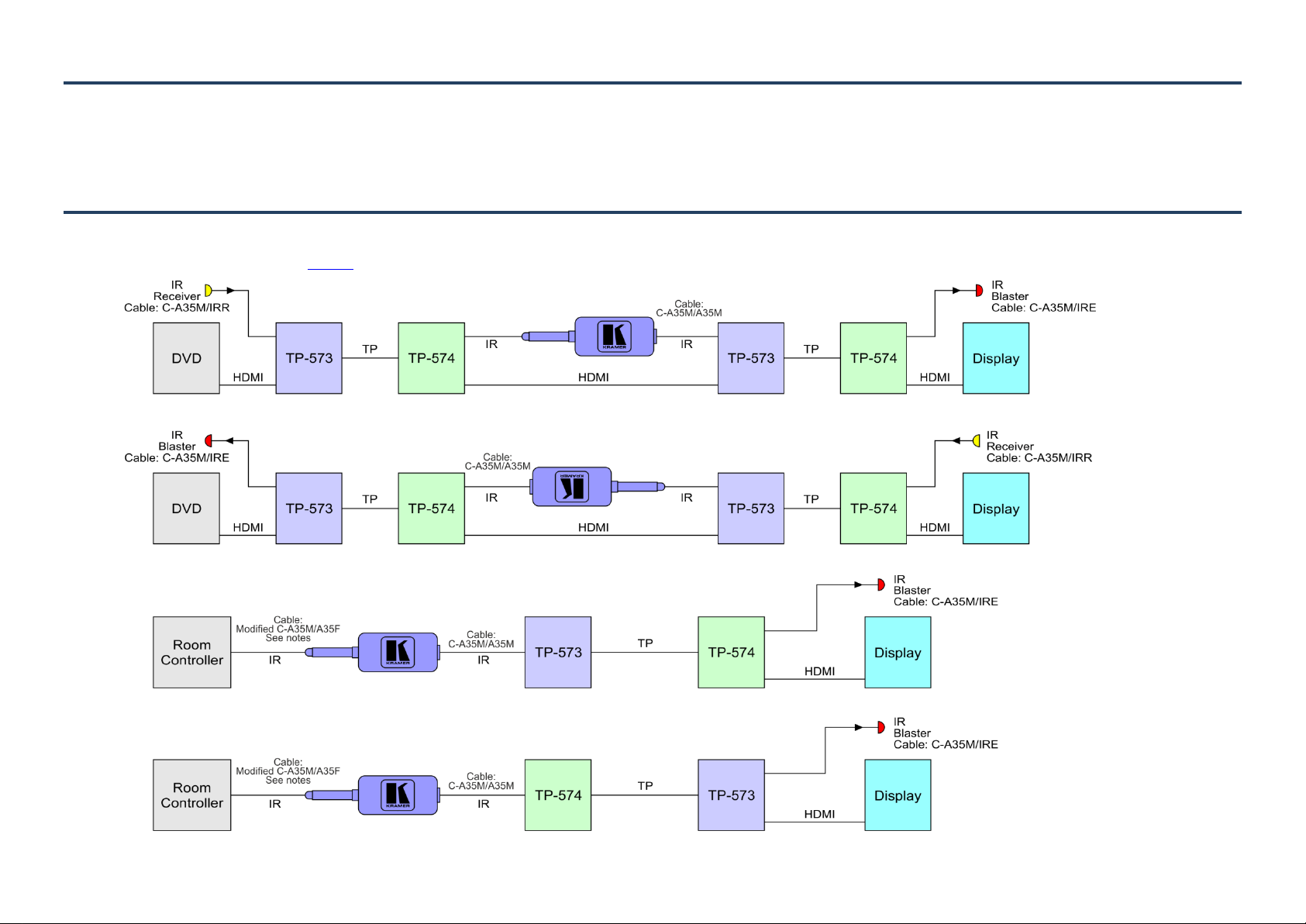
The IRD can be connected as shown in Figure 1.
Figure 1: The IR Modulator/Demodulator Example Connection Diagrams
Compatibility
INPUTS/OUTPUTS:
1 3.5mm mini jack (M)
1 3.3mm mini jack (F)
FREQUENCY:
38kHz
POWER CONSUMPTION:
3.3V DC, 25mA
OPERATING TEMPERATURE:
0° to +40°C (32° to 104°F)
STORAGE TEMPERATURE:
–40° to +70°C (–40° to 158°F)
HUMIDITY:
10% to 90%, RHL non-condensing
DIMENSIONS:
4.6cm x 1.7cm x 1.4cm (1.81” x 0.67” x 0.55”) W, D, H
WEIGHT:
0.028kg (1oz) approx.
OPTIONS:
C-A35M/IRR—IR Receiver cable 50ft
C-A35M/IRE—IR Emitter cable 10ft
C-A35M/A35M—Extension cable 50ft
C-A35M/A35F—Extension cable 50ft (to be modified to
connect to a Room Controller)
KR A ME R E L E CT RON I CS LT D .
Installation
Instructions
IR
Modulator/Demodulator
Installation Instr uctions
For the latest information on our products and a list of Kramer
distributors, visit our Web site where updates to these installation
instructions may be found
We welcome your questions, comments,
and feedback.
Web site: www.kramerelectronics.com
E-mail: info@kramerel.com
For more detailed
information
regarding this
product scan the
QR code
P/N: 29 00 -30042 0 Re v 1
P/N:
2900-300420
Rev:
1
The IRD is compatible with the following Kramer devices:
TP-573 and TP-574
TP-581 and TP-582
SL, RC and PL series
Modifying a Cable to Connect to a Room Controller
Connecting to a Room Controller with a terminal block connection requires a custom cable.
To connect to a Room Controller using the IRD:
1. Cut the male 3.5mm mini jack connector from a C-A35M/A35F cable.
2. Separate the two wires and strip approximately 7mm of insulation from the two wires.
3. Connect the wire with the stripe to the IROUT terminal block on the Room Controller.
4. Connect the wire with no stripe to the GND terminal block on the Room Controller.
Technical Specifications
 Loading...