


CG2200
Kontron
CG2
2
00
Carrier Grade
Server
Document Revision 1.1

Kontron CG2200 Carrier Grade Server Installation and Maintenance Guide
» Change History «
Revison 1.0 Initial Release
Revision 1.1 Updated Section 9.2.1 – change ‘AC line voltage
overcurrent protection per cord feed’ from 20A to
10A
Revision 1.2 Updated Section 4.12.2 – change ‘AC line
voltage overcurrent protection per cord feed’ from
20A to 10A
Revision 1.3 Adding new E5-2600 v2 processors family
» Table of Contents «
1
Introduction ...................................................................................... 1
1.1 About this Manual..................................................................................................................... 1
1.2 Manual Organization ................................................................................................................ 1
1.3 What Your Server Includes ....................................................................................................... 2
1.4 Product Accessories ................................................................................................................. 2
1.5 Additional Information and Software ......................................................................................... 3
2
Features .......................................................................................... 4
2.1 Server Components ................................................................................................................. 6
2.2 CG2200 Server Front Panel ..................................................................................................... 7
2.3 CG2200 Server Back Panel ...................................................................................................... 9
2.4 Front Panel Board .................................................................................................................. 11
2.5 LED/Switch Board .................................................................................................................. 11
2.6 Telco Alarm Module (TAM) Board ........................................................................................... 11
2.7 Hard Disk Drives .................................................................................................................... 12
2.8 SAS Hardware RAID Controller .............................................................................................. 12
2.9 SATA Disk on Module ............................................................................................................ 12
2.10 SD Flash Modules .................................................................................................................. 12
www.kontron.com
www.kontron.com

Kontron CG2200 Carrier Grade Server Installation and Maintenance Guide
2.11 Embedded USB Flash Drive ................................................................................................... 13
2.12 Server Board (Baseboard) ...................................................................................................... 13
2.13 Riser Card Assembly .............................................................................................................. 14
2.14 Ethernet NIC Ports ................................................................................................................. 15
2.15 Remote Management Module 4 .............................................................................................. 15
2.16 Power Supply Subsystem ....................................................................................................... 15
2.17 System Cooling ...................................................................................................................... 15
2.18 Processors and Memory DIMMs ............................................................................................. 16
2.18.1 Processors ......................................................................................................... 17
2.18.2 Memory ............................................................................................................. 17
3
Standard Component Installations and Upgrades .......................... 18
3.1 Before You Begin ................................................................................................................... 18
3.1.1 Tools and Supplies Needed ..................................................................................... 18
3.1.2 System References ................................................................................................. 18
3.2 General Installation Procedures .............................................................................................. 18
3.2.1 Removing the Chassis Cover ................................................................................... 18
3.2.2 Re-installing the Chassis Cover ............................................................................... 19
3.2.3 Removing the Front Bezel ....................................................................................... 20
3.2.4 Re-Installing the Front Bezel .................................................................................... 20
3.2.5 Removing a Riser Card Assembly ........................................................................... 20
3.2.6 Re-Installing a Riser Card Assembly ........................................................................ 21
3.2.7 Removing the Processor Air Duct ............................................................................ 22
3.2.8 Re-Installing the Processor Air Duct ........................................................................ 23
3.3 Internal System Components Configuration and Installation Procedures ................................. 23
3.3.1 Configuring Memory DIMMs .................................................................................... 23
3.3.2 Supported Memory .................................................................................................. 24
3.3.3 Publishing System Memory ..................................................................................... 25
3.3.4 Integrated Memory Controller Operating Modes. ...................................................... 25
3.3.5 Memory RAS ........................................................................................................... 25
3.3.6 Installing Memory DIMMs ........................................................................................ 26
3.3.7 Replacing or Removing Memory DIMMs .................................................................. 27
3.3.8 Adding or Replacing a Processor ............................................................................. 28
3.3.9 Inserting the Heat Sink ............................................................................................ 32
3.3.10 Configuring Jumpers on the Server Board .......................................................... 33
4
Optional Component Installation Procedures ................................. 36
www.kontron.com
www.kontron.com

Kontron CG2200 Carrier Grade Server Installation and Maintenance Guide
4.1 Before You Begin ................................................................................................................... 36
4.1.1 Tools and Supplies Needed ..................................................................................... 36
4.1.2 System References ................................................................................................. 36
4.1.3 Cable Routing Reference......................................................................................... 36
4.2 Installing or Replacing Hard Disk Drives ................................................................................. 39
4.2.1 Removing an HDD Carrier from the Chassis ............................................................ 39
4.2.2 Installing a Hard Drive in a Carrier ........................................................................... 40
4.3 Installing a Hardware RAID Controller .................................................................................... 42
4.4 Installing the SuperCap Module .............................................................................................. 45
4.5 Adding a Second Power Supply Module ................................................................................. 46
4.6 Installing a PCI Riser Card ..................................................................................................... 47
4.7 Installing PCI Add-in Cards ..................................................................................................... 49
4.8 Installing a Remote Management Module 4 ............................................................................ 51
4.9 Installing RMM4Lite ................................................................................................................ 54
4.10 Installing a eUSB Flash Drive ................................................................................................. 55
4.11 Installing a SATA Disk on Module (SATA DOM) ..................................................................... 56
4.12 Installing the Server into a Rack ............................................................................................. 57
4.12.1 Connecting the Power Cord ............................................................................... 57
4.12.2 Equipment Rack Precautions ............................................................................. 57
5
Server Component Replacements ................................................. 59
5.1 Before You Begin ................................................................................................................... 59
5.1.1 Tools and Supplies Needed ..................................................................................... 59
5.1.2 System References ................................................................................................. 59
5.1.3 Cable Routing Reference......................................................................................... 59
5.2 General Replacement Procedures .......................................................................................... 59
5.2.1 Removing the Support Cross Bar ............................................................................. 59
5.2.2 Removing the CPU1 and CPU2 Power Cables ........................................................ 62
5.2.3 Removing the Fan Cage .......................................................................................... 63
5.3 Replacing Fans ...................................................................................................................... 64
5.4 Replacing the Front Panel Board ............................................................................................ 65
5.4.1 Removing the Old Front Panel Board ....................................................................... 66
5.4.2 Installing the New Front Panel Board ....................................................................... 68
5.5 Replacing the LED/Switch Board ............................................................................................ 69
5.5.1 Removing the Old LED/Switch Board ....................................................................... 69
5.5.2 Replacing the LED/Switch Light Pipe Assembly ....................................................... 69
5.5.3 Installing the New LED/Switch Board ....................................................................... 69
www.kontron.com
www.kontron.com

Kontron CG2200 Carrier Grade Server Installation and Maintenance Guide
5.6 Replacing the Telco Alarms Module (TAM) ............................................................................. 70
5.6.1 Removing the Old Telco Alarms Module .................................................................. 70
5.6.2 Installing the New Telco Alarms Module................................................................... 71
5.7 Replacing the Fan Control Board ............................................................................................ 71
5.7.1 Removing the Old Fan Control Board ...................................................................... 71
5.7.2 Installing the New Fan Control Board ....................................................................... 72
5.8 Replacing the SAS Backplane Board ...................................................................................... 73
5.8.1 Removing the Old SAS Backplane Board ................................................................ 73
5.8.2 Installing the New SAS Backplane Board ................................................................. 75
5.9 Replacing the Power Distribution Board .................................................................................. 76
5.9.1 Removing the Old Power Distribution Board ............................................................ 76
5.9.2 Installing the New Power Distribution Board ............................................................. 79
5.10 Replacing the S2600CO Server Board ................................................................................... 81
5.10.1 Removing the Old Server Board from the Chassis .............................................. 81
5.10.2 Installing the New Server Board ......................................................................... 83
6
Server Utilities ............................................................................... 85
6.1 Using the BIOS Setup Utility ................................................................................................... 85
6.1.1 Using BIOS Setup ................................................................................................... 85
6.1.2 Starting Setup.......................................................................................................... 85
6.1.3 If You Cannot Access Setup .................................................................................... 85
6.1.4 Setup Menus ........................................................................................................... 85
6.2 Upgrading the BIOS ............................................................................................................... 87
6.2.1 Preparing for the Upgrade ....................................................................................... 87
6.2.2 Updating the System Firmware ................................................................................ 87
6.3 Restoring BIOS Default Settings ............................................................................................. 87
6.4 Clearing the Password ........................................................................................................... 88
6.5 BMC Force Update Procedure ................................................................................................ 88
6.6 ME Force Update Procedure .................................................................................................. 89
7
Troubleshooting ............................................................................. 90
7.1 Resetting the System ............................................................................................................. 90
7.2 Problems Following Initial System Installation ......................................................................... 90
7.2.1 First Steps Checklist ................................................................................................ 90
7.3 Hardware Diagnostic Testing .................................................................................................. 91
7.3.1 Verifying Proper Operation of Key System Lights ..................................................... 91
7.3.2 Confirming the Operating System Load ................................................................... 92
www.kontron.com
www.kontron.com

Kontron CG2200 Carrier Grade Server Installation and Maintenance Guide
7.4 Specific Problems and Corrective Actions ............................................................................... 92
7.4.1 Power Light does not Light ...................................................................................... 92
7.4.2 No Characters Appear on Screen ............................................................................ 92
7.4.3 Characters are Distorted or Incorrect ....................................................................... 93
7.4.4 System Cooling Fans do not Rotate Properly ........................................................... 93
7.4.5 Cannot Connect to a Server .................................................................................... 93
7.4.6 Diagnostics Pass but the Connection Fails .............................................................. 93
7.4.7 The (NIC) Controller Stopped Working When an Add-in Adapter was Installed ......... 94
7.4.8 The Add-in Adapter Stopped Working without Apparent Cause ................................ 94
7.4.9 System Boots When Installing a PCI Card ............................................................... 94
7.4.10 Problems with Newly Installed Application Software ........................................... 94
7.4.11 Problems with Application Software that Ran Correctly Earlier ............................ 94
7.4.12 Devices are not Recognized under Device Manager (Windows*OS) ................... 95
7.4.13 Hard Drive(s) are not Recognized ...................................................................... 95
7.5 Light-Guided Diagnostics........................................................................................................ 95
7.5.1 5 Volt Stand-by LED ................................................................................................ 95
7.5.2 DIMM Fault LEDs .................................................................................................... 95
7.5.3 System ID LED, System Status LED, and POST Code Diagnostic LED ................... 95
7.5.4 POST Error Beep Codes ......................................................................................... 98
8
Warranty ...................................................................................... 100
9
Appendix A: Safety Information ................................................... 101
9.1 Emissions Disclaimer ........................................................................................................... 101
9.2 Intended Uses ...................................................................................................................... 101
9.2.1 If AC power supplies are installed: ......................................................................... 101
9.2.2 If DC power supplies are installed: ......................................................................... 102
9.2.3 DC Power Supply 48V Input Power Mating Connector ........................................... 102
9.2.4 DC Power Supply Earth Grounding Studs on Chassis ............................................ 103
9.2.5 Overcurrent protection ........................................................................................... 103
9.2.6 Temperature and Ventilation .................................................................................. 103
9.3 Safety Cautions .................................................................................................................... 103
9.3.1 Wichtige Sicherheitshinweise ................................................................................. 105
9.3.2 Consignes de sécurité ........................................................................................... 107
9.3.3 Instrucciones de seguridad importantes ................................................................. 108
10 Appendix B: Regulatory and Certification Information .................. 113
10.1 Product Regulatory Compliance ........................................................................................... 113
www.kontron.com
www.kontron.com

Kontron CG2200 Carrier Grade Server Installation and Maintenance Guide
10.1.1 Product Safety Compliance .............................................................................. 113
10.1.2 Product EMC Compliance - Class A Compliance .............................................. 113
10.1.3 Certifications/Registrations/Declarations .......................................................... 113
10.2 Electromagnetic Compatibility Notices .................................................................................. 114
10.2.1 FCC (USA) ...................................................................................................... 114
10.2.2 Industry Canada (ICES-003) ............................................................................ 114
10.2.3 Europe (CE Declaration of Conformity)............................................................. 115
10.2.4 VCCI (Japan) ................................................................................................... 115
10.2.5 BSMI (Taiwan) ................................................................................................. 115
10.2.6 Regulated Specified Components .................................................................... 115
11 Appendix C: NEBS Considerations .............................................. 116
12 Appendix D: Getting Help ............................................................ 117
12.1 World Wide Web .................................................................................................................. 117
12.2 Telephone ............................................................................................................................ 117
12.3 Email .................................................................................................................................... 117
www.kontron.com
www.kontron.com
Kontron CG2200 Carrier Grade Server Installation and Maintenance Guide
1 Introduction
1.1 About this Manual
Thank you for purchasing and using the Kontron CG2200 Carrier Grade Server.
This manual is for trained system technicians who are responsible for troubleshooting, upgrading, and
maintaining this server. This document provides a brief overview of the features of the system followed by
a list of accessories or other components you may need or want to purchase, instructions for how to add
or replace components in the CG2200 server, and troubleshooting information.
NOTE: Always be sure to search for CG2200 on the Support website at
http://us.kontron.com/support/
since this version was published.
1.2 Manual Organization
Chapter 2 Features
provides a brief overview of the CG2200 server. In this chapter, you will find a list of the server board
features, chassis features, illustrations of the product, and product diagrams to help you identify
components and their locations
Chapter 3 Standard Component Installations and Upgrades
provides instructions for adding and replacing standard components such as processors and memory
DIMMs. Use this chapter for step-by-step instructions and diagrams for installing or replacing
components.
Chapter 4 Optional Component Installation Procedures
provides instructions for adding optional components such as PCI add-in cards, hardware RAID5
components, and an SD flash module. Use this chapter for step-by-step instructions and diagrams for
installing components.
Chapter 5 Server Component Replacements
provides instructions for replacing components such as boards and fans. Use this chapter for step-bystep instructions and diagrams for replacing components.
Chapter 6 Server Utilities
provides instructions for using the utilities that are shipped with the board or that may be required to
update the system. This includes how to navigate through the BIOS (Basic Input/Output System) setup
screens, how to perform a BIOS update, and how to reset the password or CMOS (Complementary Metal
Oxide Semiconductor). Information about the specific BIOS settings and screens is available in the Intel®
Server Board S2600CO Technical Product Specification.
Chapter 7 Troubleshooting
provides troubleshooting information. In this chapter, you will find BIOS error messages and POST
(Power-on Self Test) code messages. You will also find suggestions for performing troubleshooting
activities to identify the source of a problem.
Chapter 8 Warranty
provides the warranty information
Appendix A: Safety Information
provides the emissions disclaimer, power supply information, temperature and ventilation guidelines, and
safety cautions in multiple languages.
for the latest version of this manual with possible updates
1

Kontron CG2200 Carrier Grade Server Installation and Maintenance Guide
Appendix B: Regulatory and Certification Information
presents the regulatory and safety compliances and electromagnetic compatibility notices
Appendix D: Getting Help
1.3 What Your Server Includes
Your CG2200 server includes the following components:
• One 2U chassis
• One Intel® Server Board S2600CO with DDR3 memory slots (memory not included)
• Six removable hard drive carriers
• One DC or AC power subsystem: one hot-swappable power supply module and a power
distribution board. (The other power supply bay has a filler panel in it. For redundancy
another separately orderable power supply module must be added.)
• Six fan assemblies for cooling the processor(s), DIMM(s), PCI slot(s), and other internal
components in three cooling zones.
• A front panel board ,LED/switch board, and telco alarms module (TAM) board
• Internal cables and connectors
• See Chapter 3 for initial installation and configuration instructions.
1.4 Product Accessories
The following list shows the separately orderable components and optional accessories available for
inclusion in the initial order or to have as spares. Refer to the CG2200 Carrier Grade Server Configuration
Guide for a complete list of orderable spares and options. The Configuration Guide can be found on the
Kontron Support Website at http://us.kontron.com/support/ (search for CG2200, click on
Product Downloads, then Ordering Guide).
• LGA 2011 (socket R) support for Intel® Xeon® E5-2600 and E5-2600 v2 processors family
• Registered DDR3 Memory (RDIMM), LV-RDIMM, Unbuffered DDR3 Memory (UDIMM) with
ECC and Load Reduced DDR3 Memory (LR-DIMM)
• Up to six hot-swappable 2.5” SAS HDDs or SATA SSDs
• Hard disk drive carriers (six already shipped with the server)
• Third-party LSI-based 6 Gbit SAS hardware RAID controller
• Two front access SD media flash modules
• Internal flash storage supported (eUSB and SATADOM)
• Two risers (four FH/FL cards) and two LP adapters for a total of six PCIe Gen2/Gen3 I/O
cards
• Power cord(s)
• AC or DC power supply module (650W) for redundancy
• Intel® Remote Management Module 4 (RMM4) or RMM4Lite options
• Rack mount kits
For information about the accessories, memory, processors, and ordering information, refer to the
CG2200 Carrier Grade Server Configuration Guide on http://us.kontron.com/support/(search
for CG2200, click on Product Downloads, then Ordering Guide).
For information about third-party hardware that has been tested and can be used with your system, refer
to the CG2200 Carrier Grade Server Tested Hardware and Operating System List (THOL) on
http://us.kontron.com/support/ (search for CG2200, click on Product Downloads, then
Compatibility Matrix).
2

Kontron CG2200 Carrier Grade Server Installation and Maintenance Guide
1.5 Additional Information and Software
If you need more technical information or information about the accessories that can be used with this
CG2200 server, refer to the Technical Product Specifications (TPSs) for the system and the server board.
The TPS documents are located on the Kontron support website at
http://us.kontron.com/support. The system TPS provides in-depth technical information about
the server. The server board TPS provides in-depth technical information about the server board,
including BIOS settings and chipset information.
3
Kontron CG2200 Carrier Grade Server Installation and Maintenance Guide
2 Features
This chapter briefly describes the main features of the Kontron CG2200 Carrier Grade Server. It provides
a diagram of the product, a list of the server features, and a diagram showing the location of important
components and connections on the server system.
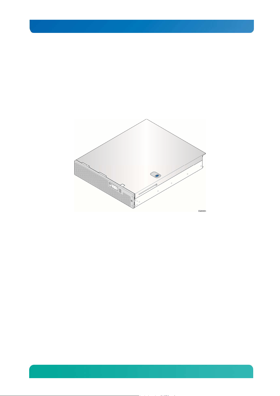
Figure 1 shows the CG2200 server.
Figure 1. Kontron CG2200 Carrier Grade Server
Table 1 summarizes the major features of the server system.
4
Kontron CG2200 Carrier Grade Server Installation and Maintenance Guide
Feature
Description
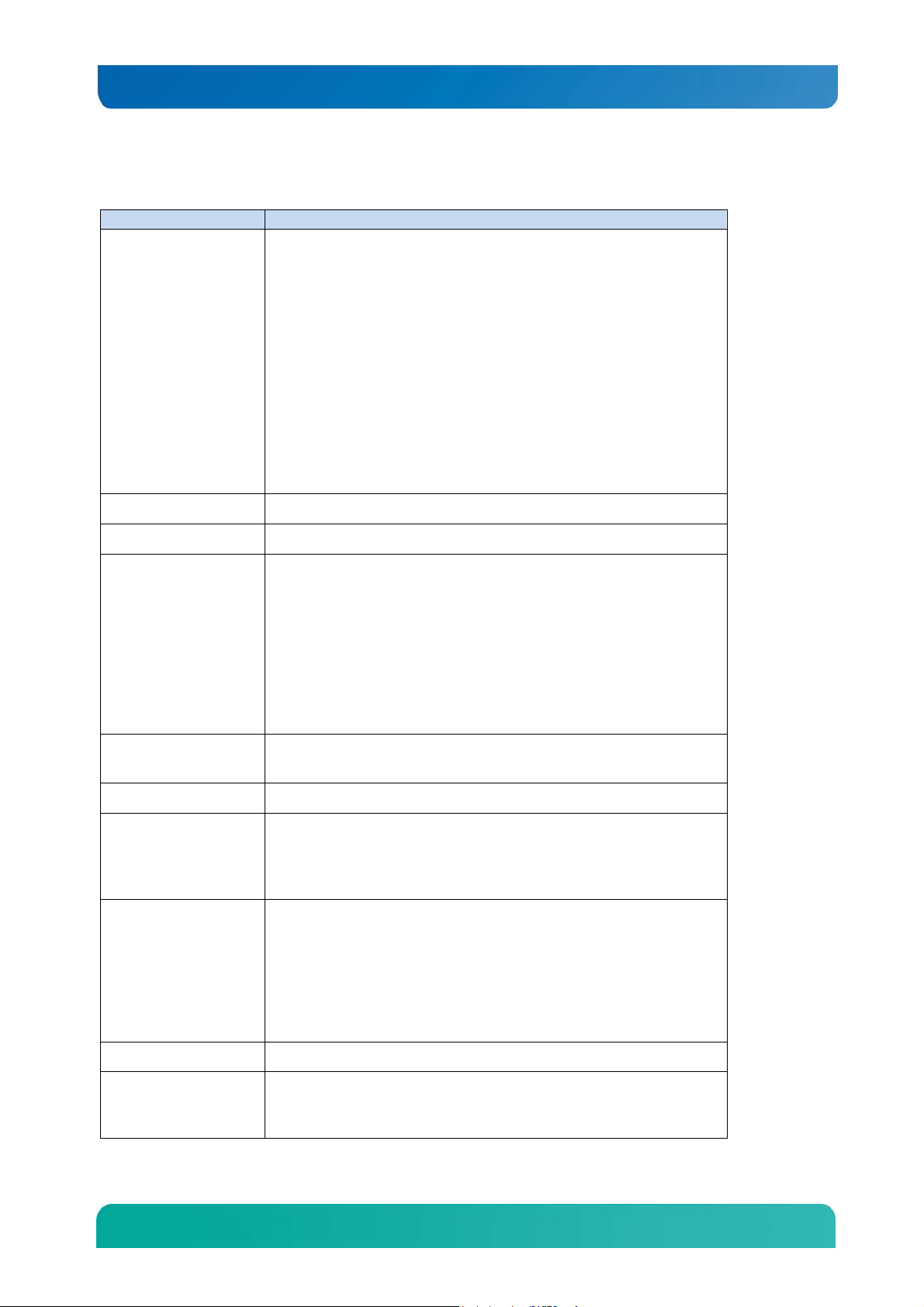
Table 1. CG2200 Server Features
External connections:
DB-15 video VGA connector (rear)
DB-15 alarms connector (rear)
RJ45 COM2 connector (front)
Four RJ45 10/100/1000 Mbps network connections (rear)
Four USB 2.0 connectors (rear)
Peripheral Interfaces
Video Integrated Matrox G200 2D video graphics controller
One USB 2.0 connector (front)
One DB9 COM1 connector (rear)
One RMM4 dedicated management NIC (optional)
Internal connections:
One internal USB headers for embedded flash drives
One RMM4 connector for an Intel® Remote Management Module 4
module (optional)
LAN Four 10/100/1000 Mbps Intel® I350 PHYs
Riser card options:
Two riser slots to support
a single slot PCIe x16 riser or
a dual slot PCIe x8 riser
Expansion Capabilities
Hard Drive Options
Peripherals Up to two SD flash modules (front panel access)
Front Panel Buttons
Front Panel LEDs
(left side slot 2)
a single slot PCIe x16 riser or
a dual slot PCIe x8 riser or
a dual PCI-X active riser
(right side slot 5)
Up to six 2.5-inch SAS HDD or SATA SDD hard drives
Onboard SAS SWRAID 0/1/10 via ESRTII or RSTe
Power on/off
System reset
Chassis ID
NMI
Power status
Chassis identification
System status
Fan status
HDD activity/fault
NIC activity
Alarms (critical, major, minor, power)
Power Supply Up to two 650W power supply modules (AC or DC)
Two redundant, hot-swappable CPU1/memory and right-side PCI
Fans
assembly area cooling fans
Two redundant, hot-swappable CPU2/PCI area cooling fans
5

Kontron CG2200 Carrier Grade Server Installation and Maintenance Guide
Feature
Description
Two redundant left-side PCI assembly cooling fans
System Management
On-board Emulex Pilot III Integrated Baseboard Management Controller
(Integrated BMC), IPMI 2.0-compliant
2.1 Server Components
Figure 2 shows the CG2200 server with the top cover removed to show the internal components.
Figure 2. CG2200 Server Components
6
Kontron CG2200 Carrier Grade Server Installation and Maintenance Guide
Table 2. CG2200 Server Components
Item Description Item Description
A
B Earth Ground O CPU 2
C
D Right-side riser card assembly Q
E CPU and DIMM air duct R Telco alarm module (TAM) board
F Chassis support crossbeam S RJ45 COM1 port and USB port (2 connectors)
G System fans (six) T Front panel board (FPB)
H Hard Drive Bay U LED board
I Air baffle for left-side riser card V SD flash card slots (2)
J Left-side riser card assembly W Power distribution board (PDB)
K Baseboard PCI slot 2 for left-side risers only X Fan control board
L
Redundant, hot-swappable AC or DC power
supply modules
PCI adapter external port access for five
adapters
Baseboard PCI slot 3 for internal hardware RAID
adapter only
N Baseboard PCI slot 5, for right-side risers only
P CPU 1
16 DDR3 memory DIMM slots, two banks of four
DIMMs for each processor (CPU 1 slots shown)
Y
Power supply cage for two power supply
modules
M Baseboard PCI slot 4, for LP adapters only Z Intel® S2600CO Server Board
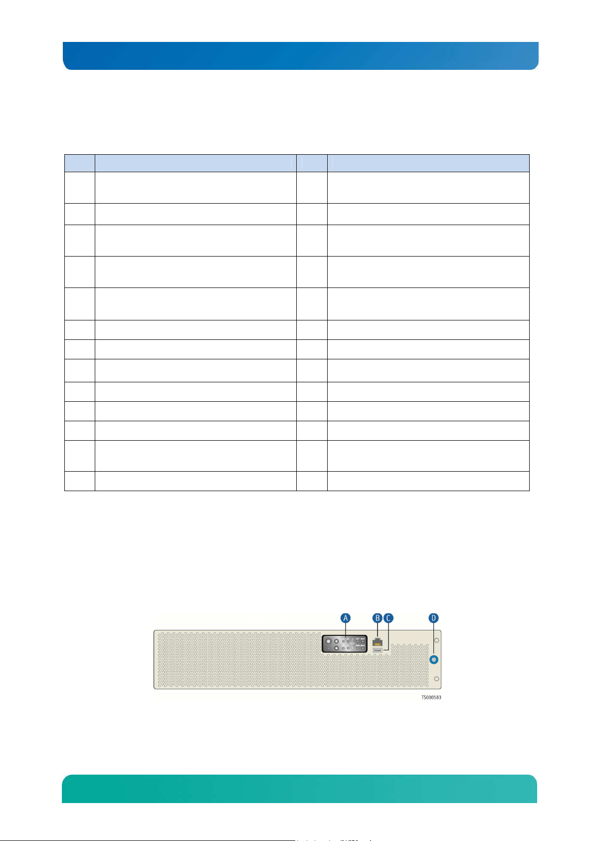
2.2 CG2200 Server Front Panel
Figure 3 shows the front panel of the CG2200 server with the bezel installed.
Figure 3. CG2200 Server Front View (Bezel Installed)
7

Kontron CG2200 Carrier Grade Server Installation and Maintenance Guide
Item Description Item Description
A Front panel control buttons
and status indicator and
telco alarm LEDs
B RJ45 COM2 port D Bezel captive screw
C USB port
Figure 4 shows the front panel of the CG2200 server with the bezel removed.
Figure 4. CG2200 Server Front View (Bezel Removed)
Item Description Item Description
A Hard disk drive slot 5 G
B Hard disk drive slot 4 H RJ45 serial port (COM1/serial A)
C Hard disk drive slot 3 I USB port
D Hard disk drive slot 2 J SD 0 and SD 1 flash modules
E Hard disk drive slot 1 K SD flash LED
F Hard disk drive slot 0 L ESD ground strap attachment
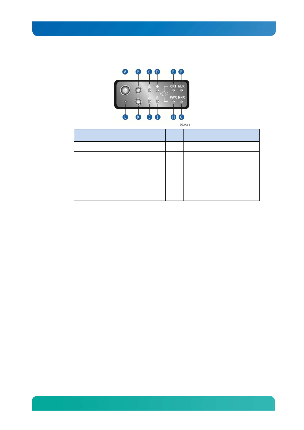
Figure 5 shows the CG2200 server control panel.
Front panel control buttons,
status indicator and telco alarm
LEDs
8
Kontron CG2200 Carrier Grade Server Installation and Maintenance Guide
Figure 5. CG2200 Server Control Panel
Item Description Item Description
A Power button G Minor alarm (amber)
B System reset button H Power alarm (amber)
C Chassis information LED I HDD activity LED
D Fan status LED J NIC1/NIC2 activity LED
E Critical alarm (amber or red†) K Chassis ID button
F Major alarm (amber or red†) L NMI button
† Critical and Major alarm indicators are bi-color LEDs that can be configured to be yellow or
red by means of an SDR TAM setting. Yellow is the default color.
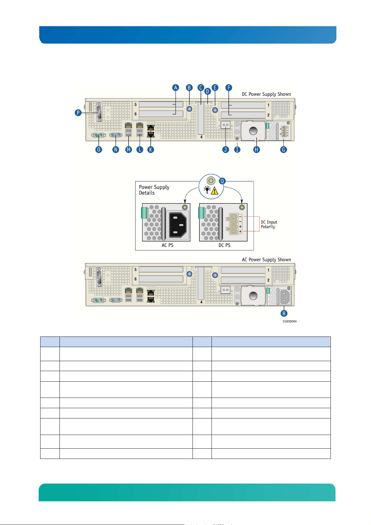
2.3 CG2200 Server Back Panel
Figure 6 shows the back panel of the CG2200 server.
9
Kontron CG2200 Carrier Grade Server Installation and Maintenance Guide
B
Thumb screw to secure
right PCI
assembly (A)
K
GbE NIC3 and NIC 4 (NIC3 on top)
visible from outside of chassis
)
Figure 6. CG2200 Server Rear View
Item Description Item Description
A
Right1 2-slot FL/FH PCI assembly (slots 5 and 6)
C
LP PCI adapter (slot 4)
Internal LP PCI adapter (baseboard slot 3, not
D
E
Thumb screw to secure left PCI assembly (F)”
F
Left1 2-slot FL/FH PCI assembly (slots 1 and 2)
Power supply 1 (shown with PC power supply
G
installed)
Optional power supply 2 (filler panel shown)2
H
I
Earth Ground studs (dual hole lug shown)
RMM4 NIC (optional)
J
L
GbE NIC2, USB2 and USB3 (USB2 on top)
M
GbE NIC1, USB0 and USB1 (USB0 on top)
N
Video connector
O
DB9 Serial Connector
P
TAM dry relay connector
Q
Power supply LED signals
R
Power supply 1 (shown with AC power supply
10

Kontron CG2200 Carrier Grade Server Installation and Maintenance Guide
Item
Description
Item Description
3
. If RMM
4 NIC is not used,
a filler panel occupies this space
installed)
NOTES:
1. Right and left notation for PCI assemblies is when looking from the front of the system.
21: In non-redundant configurations, power supply slot 2 must have a filler panel installed.
2.4 Front Panel Board
The front panel (FP) board is located behind the front bezel and in front of the fans. The FP Board
provides the following feature set:
The FP Board provides the following feature set:
• Two USB ports: one to drive the USB port on the combo RJ45 and USB connector and one
to drive the SD flash module controller(s).
• Serial RS-232 signals to the front panel serial port on the combo RJ45 and USB connector
• Control circuitry for driving the NIC activity LED, the system status LED, the power LED, and
the disk activity LED, which are all located on the LED/switch board
• On-board LED that indicates USB flash drive activity
• System power state and status indicators -- power, reset, and NMI switches
NOTE: There may be features (for future use) in addition to those in this list.
2.5 LED/Switch Board
The LED/switch board provides input selection switches and LED status indicators for the server system.
The LED/switch board is connected to the FP board and receives status and alarm signals from it. The
board has the following features:
• Connects the front panel board signals to the front panel. There are four switches and six
LEDs. The power status LED and the chassis ID LED are embedded in the switch and the
other four are on the control panel. (See Figure 5.)
• On board switches for power, reset, ID, and NMI
• On board LEDs to indicate power status, chassis ID, system status, HDD activity/fault, NIC
activity, and fan status
NOTE: For information about the telco alarm LEDs that are also on the front panel, see Section 7.5, Light-
Guided Diagnostics
2.6 Telco Alarm Module (TAM) Board
The CG2200 server Telco Alarms Module (TAM) board provides the connector interface and supporting
logic for the telco alarms function. The TAM board also provides an alarms function with fault relays and
access by cable to the fault relay contacts at the back of the system. A ribbon cable connects the TAM
board to the front panel board.
11

Kontron CG2200 Carrier Grade Server Installation and Maintenance Guide
For detailed information about the telco alarms and fault relays, see the “Telco Alarms (TAM)” chapter in
the CG2200 Carrier Grade Server Technical Product Specification on the Kontron support website at
http://us.kontron.com/support.
2.7 Hard Disk Drives
The CG2200 Carrier Grade Server chassis supports up to six hard disk drives which are accessible from
the front of the chassis with the bezel removed. The hard disk drives are mounted in removable drive
carriers that latch into the drive bay sub-assembly. Up to six 2.5-inch hot-swappable SAS technology
rotating hard drives and/or SATA solid state drives can be mounted in the drive bay.
Drives can consume up to 12W of power, each. Drives used in this server must be specified to run at a
maximum ambient temperature of 40°C.
NOTES:
1) SATA rotating HDDs are not recommended for use in this system because they are sensitive to
rotational vibration from system fan blades and other HDDs.
2) The CG2200 server does not support all SAS or SATA drive models. For a list of validated hard drive
manufacturers and hard drive types, refer to the Tested Hardware and Operating System List (THOL) on
the Kontron website at
Downloads, then Compatibility Matrix).
http://us.kontron.com/support/
(search for CG2200, click on Product
2.8 SAS Hardware RAID Controller
Software RAID 0/1/10 is supported for all six SAS drives or SATA SSDS. If additional levels of software
RAID are needed, see the Configuration Guide for orderable options.
Hardware RAID is available as a separately-orderable kit and additional CG2200 RAID cable kit. This kit
provides cables and brackets to support both an LSI and an Intel hardware RAID controller.
For more information about these options, refer to the Configuration Guide located on the support website
at http://us.kontron.com/support/, (Search for CG2200, click on Product Downloads, then
Ordering Guide).
2.9 SATA Disk on Module
A SATA DOM can be implemented on the server board. To use this HDD functionality, you need a
separately-purchased card. For a list of qualified third party vendors, see the Tested Hardware and
Operating System List (THOL). The latest version of the Configuration Guide is located on the Kontron
support website at http://us.kontron.com/support/ (search for CG2200, click on Product
Downloads, then Ordering Guide). The latest version of the THOL is located on the support website at
http://us.kontron.com/support (search for CG2200, click on Product Downloads, then
Compatibility Matrix).
2.10 SD Flash Modules
There are two front-accessible USB SD flash modules that support two SD cards. For a list of validated
SD cards to use with these modules, see the Tested Hardware and Operating System List (THOL) on the
Kontron website at http://us.kontron.com/support/ (search for CG2200, click on Product
Downloads, and then Compatibility Matrix).
12
Kontron CG2200 Carrier Grade Server Installation and Maintenance Guide
2.11 Embedded USB Flash Drive
A eUSB flash drive can be installed optionally on the server board. To use this feature, you need a
separately-purchased eUSB drive. For a list of qualified third party vendors, see the Tested Hardware
and Operating System List (THOL). The latest version of the THOL is located on the support website at
http://us.kontron.com/support
Matrix).
(search for CG2200, click on Product Downloads, then Compatibility
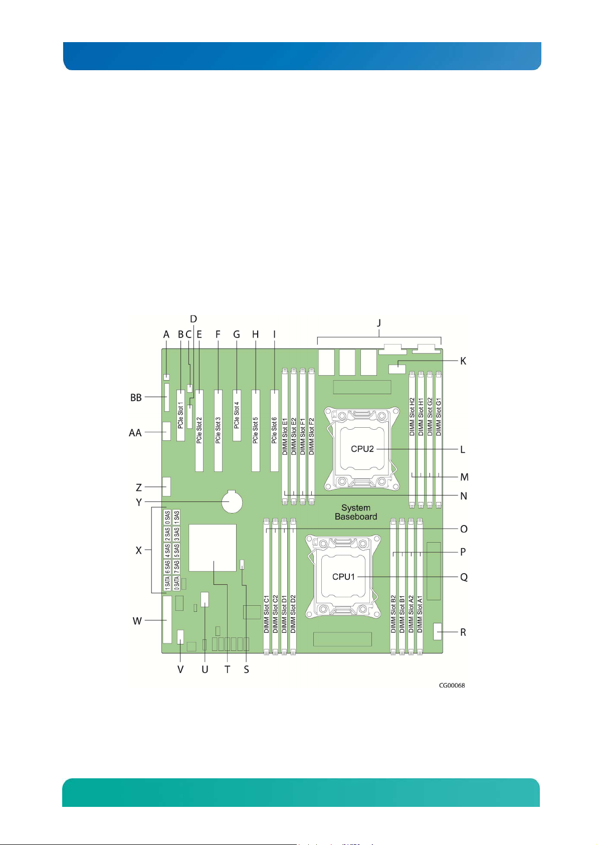
2.12 Server Board (Baseboard)
The CG2200 server uses the Intel® S2600CO server board for the baseboard. The processors and
memory DIMMs are on the server board and support for several optional accessories, such as two PCI
riser slots, the platform management subsystem, and RMM4 Lite and RMM4 DMN connectors, also .
Figure 7 shows the key components and connectors on the S2600CO server board.
Figure 7. Baseboard Components and Connectors
13
Kontron CG2200 Carrier Grade Server Installation and Maintenance Guide
Item Description Item Description
A Chassis intrusion header (not
supported on the CG2200 server)
B PCIe slot 1, PCI Express* Gen3 P CPU1 DIMM slots (A, B)
C RMM4Lite key Q CPU1
D RMM4 NIC R CPU1 power connector
E PCIe slot 2, PCI Express* Gen3 S SAS software RAID key
F PCIe slot 3, PCI Express* Gen3 T PCH chipset
G PCIe slot 4, PCI Express* Gen3 U eUSB connector
H PCIe slot 5, PCI Express* Gen3 V SMBus
I PCIe slot 6, PCI Express* Gen3 W Main power connector
J Rear I/O ports X SAS/SATA connectors
K CPU2 power connector Y CMOS battery
L CPU2 Z Front panel USB connector
M CPU2 DIMM slots (G, H) AA Serial B connector
N CPU2 DIMM slots (E, F) BB SSI front panel connector
O CPU1 DIMM slots (C, D)
2.13 Riser Card Assembly
The Intel® Server Board S26000CO has two riser slots capable of supporting riser cards on the right side
and left side of the chassis. Baseboard PCIe slot 2 and PCIe slot 5 support the riser boards in the
CG2200 system. Baseboard PCIe slot 2 supports a single slot PCIe X16 riser and a dual slot PCIe X8
riser. These risers are referred to as the “left side’ risers since the boards plug in on the left side of the
chassis as viewed from the front of the server. Baseboard PCIe slot 5 supports a single slot PCIe X16
riser, a dual slot PCIe X8 riser, and a dual PCI-X active riser. These risers are referred to as the “right
side” risers since the boards plug in on the right side of the chassis.
Once PCI add-in cards are installed and the riser card assembly is remounted in the chassis, the cards
are accessible from the rear of the server chassis.
Table 3 identifies the card configurations and the connector types used.
14
Kontron CG2200 Carrier Grade Server Installation and Maintenance Guide
Table 3. Riser Card Configuration Options
Riser Card Option Slot Configuration
PCI Express passive riser single slot x16
Right-side riser (baseboard slot 5)
PCI Express passive riser dual slot x8
Right-side riser (baseboard slot 5)
PCI Express/PCI-X active riser
Right-side riser (baseboard slot 5)
PCI Express passive riser single slot x16
Left-side riser (baseboard slot 2)
PCI Express passive riser dual slot x8
Left side riser (baseboard slot 2)
Single full-height PCI Express connector
Two full height PCI Express x8 connectors
Two full-height PCI-X 133 connectors
Single full-height PCI Express connector
Two Full height PCI Express x8 connectors
2.14 Ethernet NIC Ports
The S2600CO server board (baseboard) provides four dual network interface controller (NIC) RJ45
connectors oriented side-by-side on the back edge of the board and accessible at the rear I/O panel.
Additional rear-accessible GbE NIC ports can be added to the system by using full-height PCI-X/PCIe
add-in cards or low-profile PCIe add-in cards
2.15 Remote Management Module 4
RMM4 can be implemented optionally on the iBMC on the S2600CO server board. To use this feature, a
separately-orderable RMM4 kit must be installed. An RMM4Lite kit can also be purchased to enable
advanced features in the iBMC without a dedicated management NIC.
2.16 Power Supply Subsystem
The power supply subsystem consists of up to two AC or DC power supply modules (two needed for
redundancy) and a power distribution board (PDB). One power supply module is included with the server
with a filler panel in the second power supply slot.
The power supply module is rated for 650W output capability in full AC or DC input voltage range. The
minimum steady-state DC input voltage at which the equipment remains fully operational is -38 VDC. The
nominal operating voltage of the DC system is -48 VDC.
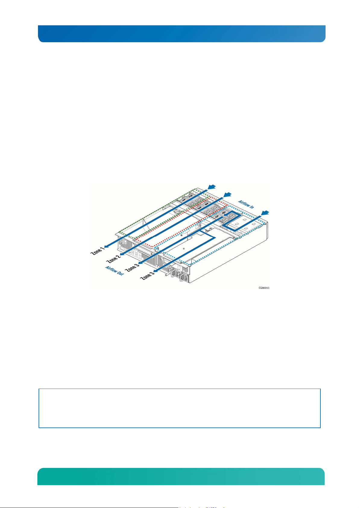
2.17 System Cooling
There are three main cooling areas in the CG2200 server as illustrated in
Figure 8.
15
Kontron CG2200 Carrier Grade Server Installation and Maintenance Guide
• Zone 1 (green dotted lines) contains fans 1 and 2, which cool CPU1, CPU2, DIMMs A1, A2, B1, B2,
G1, G2, H1, H2 and all other components in this zone. Air flows through the front bezel to the rear of
the chassis (zone 1 arrow).
• Zone 2 (red dotted lines) contains fans 3 and 4 which cool DIMMs C1, C2, D1, D2, E1, E2, F1, F2,
the right-side PCI assembly, and all other components in this zone. . Air flows through the front bezel
to the rear of the chassis (zone 2 arrow).
• Zone 3 (blue dotted lines) contains fans 5 and 6 which cool the six HDDs, the two LP PCI adapters in
baseboard slots 3 and 4, the left-side PCI assembly and all the other components in this area. Air
flow takes two routes for this zone; from the front bezel over the drive bay to the fans and straight
back to the rear of the chassis (left zone 3 arrow) or over the drive bay to the fans and then back over
the power supplies to the rear of the chassis. (right zone 3 arrow).
• Internal power supply fans as well as system fans 5 and 6 cool the power distribution board (PDB)
and power supply modules.
Figure 8. CG2200 Server Cooling Areas
The three-zone cooling subsystem is sized to provide cooling for:
• Up to two server board processors
• Up to 256 GBytes of DDR3 memory
• Up to six SAS hard disk drives
The cooling subsystem meets acoustic and thermal requirements at the lower fan speed settings. At the
higher fan speed settings, thermal requirements are met for the maximum ambient temperatures, but
acoustic requirements are not met.
2.18 Processors and Memory DIMMs
NOTE: To avoid integration difficulties and possible board damage, your server must meet the requirements
outlined below. For a list of qualified processors refer to the Configuration Guide located on the support
website at http://us.kontron.com/support/ (search for CG2200, click on Product Downloads, then
Ordering Guide). For a list of qualified DIMMs refer to the Tested Memory List at
http://us.kontron.com/support/ (search for CG2200, click on Product Downloads, then
Compatibility Matrix).
16

Kontron CG2200 Carrier Grade Server Installation and Maintenance Guide
2.18.1 Processors
The S2600CO server board accommodates two processors from Intel® Xeon® E5-2600 and E5-2600 v2
processor series. These processors can be ordered from Intel or an authorized distributor using the
Kontron part numbers listed in the CG2200 Carrier Grade Server Configuration Guide.
2.18.2 Memory
The S2600CO server board supports 16 DIMM slots – two DIMM slots/channel – four memory
channels/processor. Support for Registered DDR3 Memory (RDIMM), LV-RDIMM, Unbuffered DDR3
Memory (UDIMM) with ECC and Load Reduce DDR3 Memory (LR-DIMM. Memory DDR3 data transfer
rates of 800, 1066, 1333, and 1600 MT/s.
17
Kontron CG2200 Carrier Grade Server Installation and Maintenance Guide
3 Standard Component Installations and Upgrades
3.1 Before You Begin
Before working with your server product, pay close attention to the safety instructions provided in this
manual. See Appendix A, “Appendix A: Safety Information”
Warning: Electrostatic discharge (ESD) and ESD protection: ESD can damage disk drives, boards, and other
parts. We recommend that you perform all procedures in this chapter only at an ESD workstation. If one
is not available, provide some ESD protection by wearing an antistatic wrist strap attached to chassis
ground (any unpainted metal surface) on your server when handling parts.
3.1.1 Tools and Supplies Needed
• #1 and #2 Phillips (cross-point) screwdrivers (or interchangeable tip screwdriver with #1 and
#2 Phillips bits)
• Personal grounding device such as an anti-static wrist strap and a grounded conductive pad
3.1.2 System References
All references to left, right, front, rear, top, and bottom assume that you are facing the front of the server,
as it would be positioned for normal operation.
3.2 General Installation Procedures
The following sections present general installation and removal procedures that are required before
removing or installing internal components that are not hot-swappable.
3.2.1 Removing the Chassis Cover
The CG2200 server must be operated with the top cover in place to ensure proper cooling. You will need
to remove the top cover to add or replace components inside the chassis that are not hot-swappable.
CAUTION: 5V standby power is present inside the chassis whenever the power supply module(s) are
connected to a power source. Before removing the top cover, always power down the server and
unplug all peripheral devices and the power cable.
A non-skid surface or a stop behind the server may be needed to prevent the server from sliding on your
work surface.
1. Observe the safety and ESD precautions in Appendix A, “Appendix A: Safety Information”.
2. Turn off all peripheral devices connected to the server.
Turn off the server.
3. Disconnect the power cord(s).
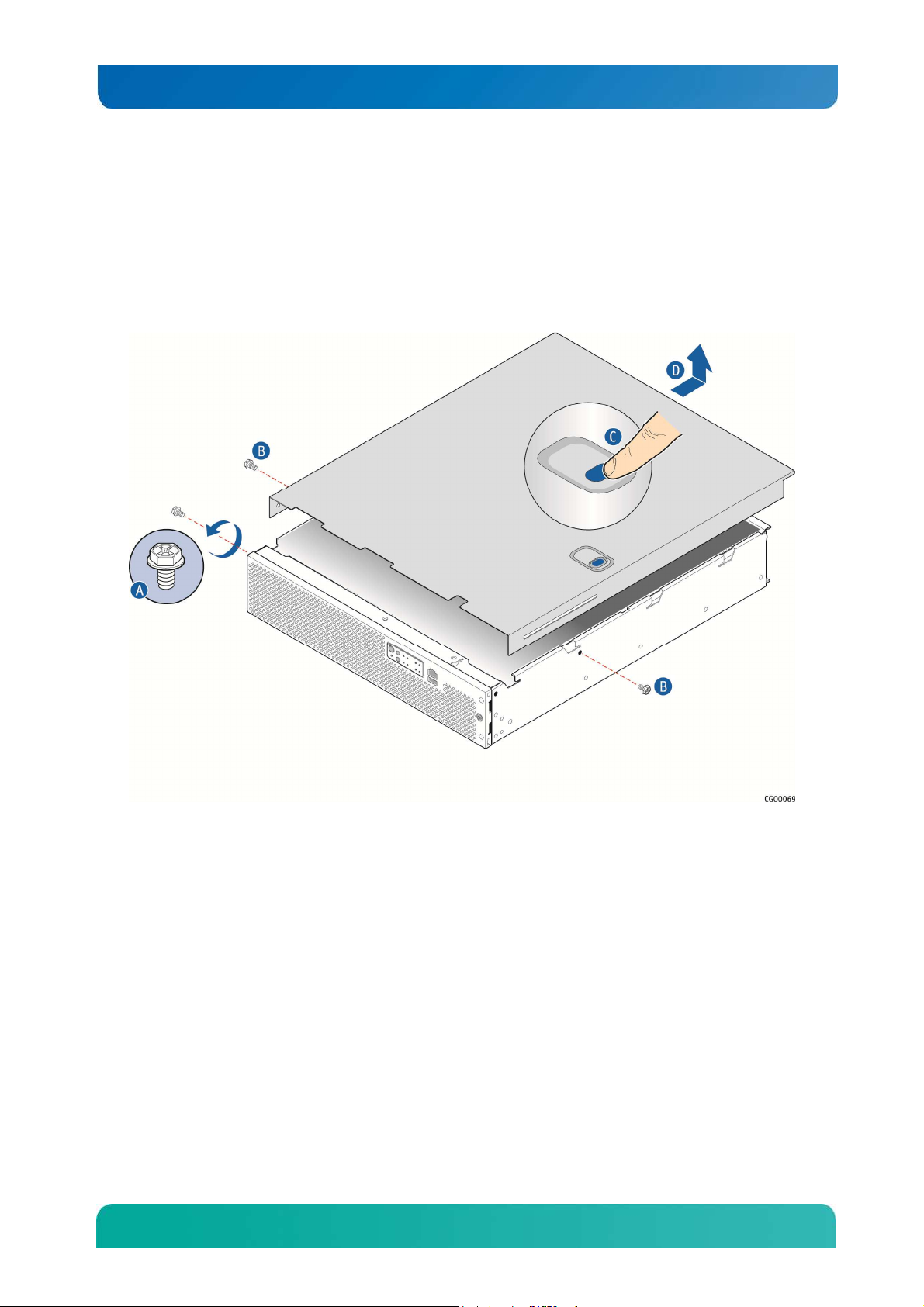
Figure 9 shows the top cover and how it is removed.
Removing the Cover
1. Remove the hex HD Phillips 6-32 shipping screw at the front left side of the cover, if it is still
attached, and save it for future use. (
2. Figure 9, “A”)
18
Kontron CG2200 Carrier Grade Server Installation and Maintenance Guide
3. Remove the two shoulder screws (one on each side) from the cover. (“B”)
4. While holding the blue unlocking button at the middle of the top cover ( “C”), slide the cover
backwards until it stops and the edge clears the lock bracket on the rear panel of the chassis
5. Lift the cover straight up to remove it from the chassis. (“D”)
Figure 9. Removing the Cover
3.2.2 Re-installing the Chassis Cover
When you are finished working inside the chassis, you must put the cover back on before turning the
server back on. This step is required to ensure proper cooling.
Re-Installing the Cover
1. Starting from the rear of the chassis, align the tab on the rear right edge of the cover with the lock
bracket on the outside of the rear panel and place the cover down over the chassis with the side
edges outside the chassis walls.
2. Slide the cover forward until it clicks into place.
3. Install the shipping screw if tooled entry is required or if the unit will be shipped.
4. Replace the two shoulder screws (one on each side) to fasten the cover to the chassis frame.
5. Torque screws to 8lbf*in.
6. Reconnect all peripheral devices and the power cord(s).
19
Kontron CG2200 Carrier Grade Server Installation and Maintenance Guide
CAUTION: This unit must have the cover installed when it is running to ensure proper cooling.
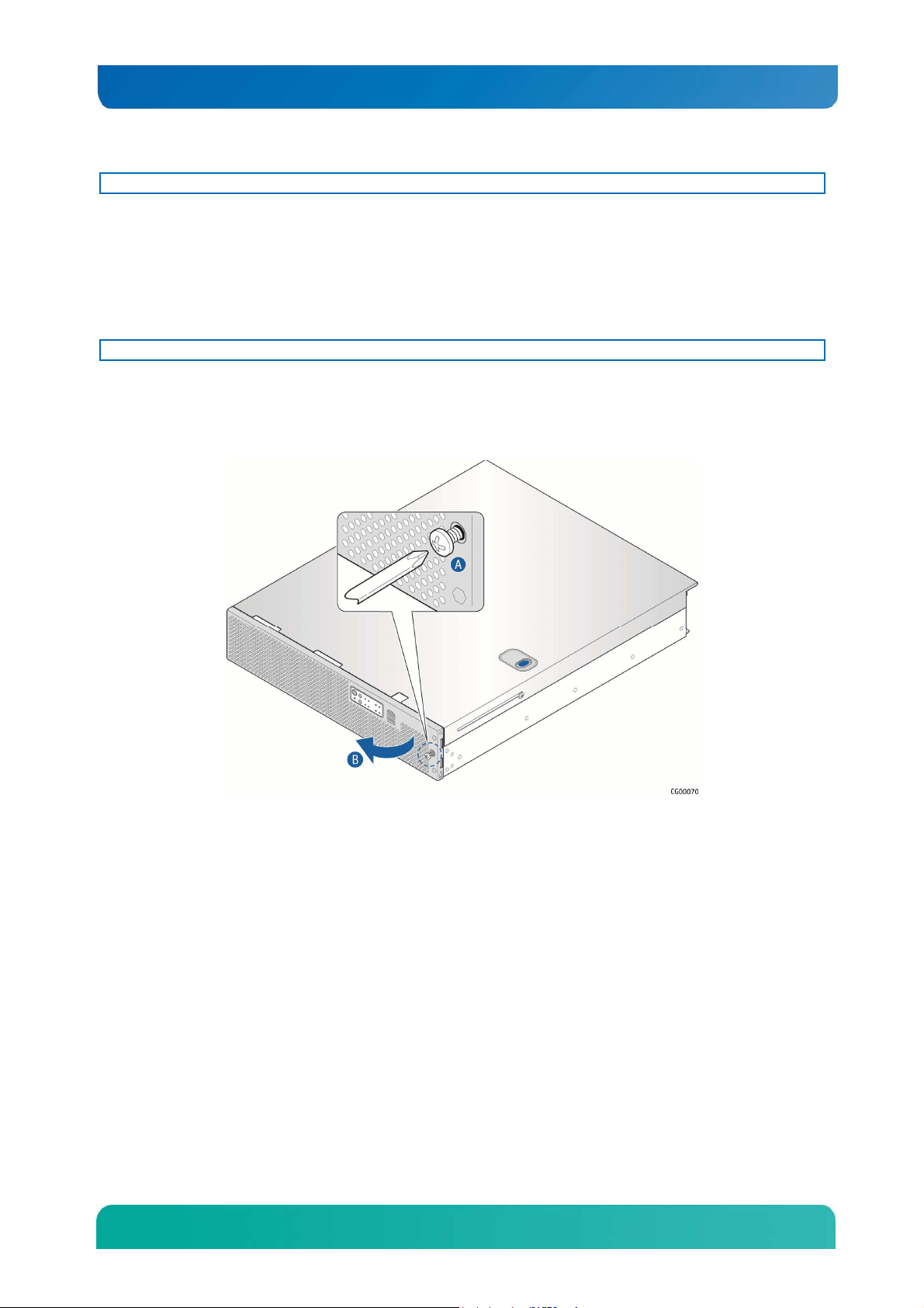
3.2.3 Removing the Front Bezel
You need to remove the front bezel for tasks such as:
• Installing or removing hard disk drives or an SD flash card
• Observing the individual hard disk drive activity/fault indicators
• Replacing the control panel LED/switch board
NOTE: The server does not have to be powered down just to remove the front bezel.
1. Loosen the captive bezel retention screw on the right side of the bezel (Figure 10, “A”).
2. Rotate the bezel to the left to free it from the pins on the front panel, (“B”) and remove it.
Figure 10. Removing the Front Bezel
3.2.4 Re-Installing the Front Bezel
1. Insert the tabs on the left side of the bezel into the slots on the front panel of the chassis.
2. Move the bezel toward the right and align it on the front panel pins.
3. Snap the bezel into place and tighten the retention screw to secure it.
3.2.5 Removing a Riser Card Assembly
One or both of the riser card assemblies has to be removed from the chassis to perform tasks such as:
• Installing or replacing a riser card and any PCI add-in card(s)
• Working with any components on the server board that are near the riser card assembly
• Installing or replacing processors or memory DIMMs
• Removing the server board
To remove a riser card assembly:
1. Power down the server and remove all peripheral devices and the power cord(s)
2. Remove the chassis cover. For instructions, see “Removing the Chassis Cover” in Section 3.2.
20
Kontron CG2200 Carrier Grade Server Installation and Maintenance Guide
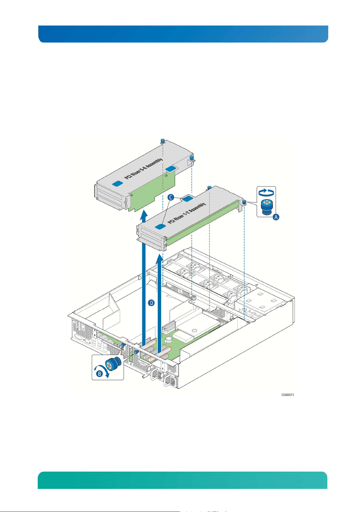
Loosen the two blue captive retention screws (
3. Figure 11, “A”) at the front of the riser assembly and the blue captive screw at the rear of the chassis
(“B”).
4. Using the two blue touch points (“C”), lift the riser card assembly out of the chassis (“D”).
Figure 11. Removing the Riser Card Assemblies
3.2.6 Re-Installing a Riser Card Assembly
To re-install the riser card assembly:
1. Position the riser front tabs over the holes on the PCI support cross bar. (Figure 11, “A”).
21

Kontron CG2200 Carrier Grade Server Installation and Maintenance Guide
2. Using the blue touch points on the top of the assembly (“C”), press down to mate the riser card with
the header on the server board (Slot 2 for the left-side riser and slot 5 for the right-side riser.)
NOTES: 1) To avoid damaging the card edge, be sure that the card is lined up straight with the header, not on
an angle.
2) If a hardware RAID controller card is installed in PCI slot 4, be careful not to damage the diagnostic
pins at the back of the card next to the rear chassis panel when re-installing the left-side riser assembly.
3. Align and then tighten the blue captive retention screws at the front of the assembly with the holes on
the support cross bar (“A”) and on the rear of the chassis. (“B”.
4. Replace the chassis cover. For instructions see “Re-Installing the Cover” in Section 3.2.
3.2.7 Removing the Processor Air Duct
The black plastic processor air duct must be removed to access the processors and the memory DIMMs.
The air duct is required to ensure proper air flow within the chassis, so be sure that it is in place again
before re-installing the chassis cover.
To remove the processor air duct:
1. Power down the server and remove all peripheral devices and the power cord(s)
2. Remove the chassis cover. For instructions, see “Removing the Chassis Cover”.
3. Remove the right-side (slot 5) riser card assembly. For instructions, see “Removing a Riser Card
Assembly”.
4. Loosen the captive retention screw on the support cross bar that secures the air duct.
5. Rotate the air duct slightly to the left to clear the notch on the PCI riser assembly connector and slide
the air duct backwards. Lift the air duct straight up to remove it. (Figure 12)
22
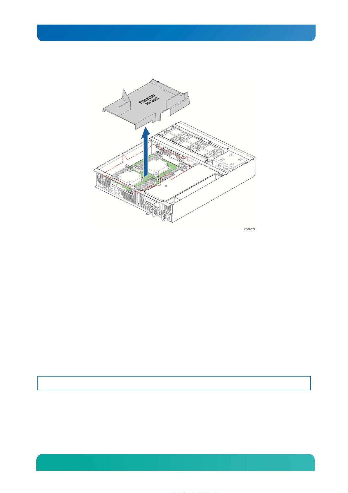
Kontron CG2200 Carrier Grade Server Installation and Maintenance Guide
Figure 12. Removing the Processor Air Duct
3.2.8 Re-Installing the Processor Air Duct
The air duct is required to ensure proper air flow within the chassis, so be sure that it is in place again
before re-installing the chassis cover.
1. Place the processor air duct over the processor sockets and DIMMs. Align the standoff on the top right
with the captive screw on the support cross bar. Tighten the screw to secure the air duct.
2. Re-install the riser card assembly. For instructions, see “Re-Installing a Riser Card Assembly”.
3. Replace the chassis cover and reconnect all power cords and external peripheral devices. For
instructions, see “Re-Installing the Cover”.
3.3 Internal System Components Configuration and Installation
Procedures
This section covers separately-orderable components that must be installed for your server to operate. It
also covers replacing these components and where relevant, such as with memory DIMMs, how to
configure them.
You install your separately-orderable DIMMs and processors on the Intel® Server Board S2600CO, which
is the baseboard for this server.
NOTE: Be sure to read the following information about the configuration rules and memory feature options
before you begin.
3.3.1 Configuring Memory DIMMs
The memory DIMM slots are located in two separate banks on the S2600CO server board. Detailed
information about the memory subsystem in the CG2200 server can be found in the Intel® Server Board
S2600CO Family Technical Product Specification located on the Kontron support website
23
 Loading...