


Konica Minolta C-403 DI5510/DI7210, FN-6 DI5510/DI7210, OT-104, COVER INSERTER B DI5510/DI7210, FN-112 DI5510/DI7210 Manual
...7663-4396-11
OPTION
SERVICE MANUAL
C-403/C-404
Cover Inserter B/E
EDH-4/EDH-7
FN-115/FN-7
FN-112/FN-6
FN-121/FN-10
FN-113/FN-122
OT-104
PK-2
PK-5
ZK-2/ZK-3
2004.01 Ver. 1.0

SERVICE MANUAL
C-403/C-404
2004.01 Ver. 1.0

CONTENTS
SAFETY AND IMPORTANT WARNING ITEMS |
|
Refer to the Di551/Di650/Di5510/Di7210 service |
|
manual on page .................................................... |
S-1 |
CONTENTS
1. OUTLINE
C-403/C-404 PRODUCT SPECIFICATIONS ............ |
1-1 |
CENTER CROSS-SECTIONAL DRAWING .............. |
1-2 |
DRIVE SYSTEM DRAWING...................................... |
1-3 |
[1] Paper feed drive section............................. |
1-3 |
[2]Stacked paper up/down wire drive section.1-4
2. UNIT EXPLANATION
PAPER FEED SECTION ........................................... |
2-1 |
|
[1] |
Composition ............................................... |
2-1 |
[2] |
Mechanisms ............................................... |
2-1 |
[3] First paper feed control .............................. |
2-2 |
|
[4] Up/down plate drive control........................ |
2-4 |
|
[5] Remaining paper detection/No paper |
|
|
|
detection control ......................................... |
2-5 |
3. DISASSEMBLY/ASSEMBLY
PAPER FEED SECTION ........................................... |
3-1 |
[1]Cleaning the Paper Dust Removing Brush.3-1
[2]Cleaning the LT feed PS (PS106)/
LT first paper feed PS(PS107) ................... |
3-1 |
[3]Removing and Reinstalling the
Paper Feed Roller Unit............................... |
3-2 |
[4]Replacing the Paper Feed Roller Rubber/
Feed Roller Rubber .................................... |
3-2 |
[5]Replacing the Double Feed
Prevention Roller Rubber ........................... |
3-3 |
[6]Replacing the LT feed MC (MC101)/
|
LT first paper feed MC (MC102)................. |
3-5 |
[7] |
Replacing the C-403 Up/Down Wires......... |
3-6 |
[8] |
Replacing the C-404 Up/Down Wires....... |
3-10 |
1 OUTLINE
3 DIS./ASSEMBLY 2 UNIT EXPLANATION
3 DIS./ASSEMBLY |
|
2 UNIT EXPLANATION |
|
1 OUTLINE |
|
|
|
|
|
page Blank

1 OUTLINE
1
OUTLINE

1 OUTLINE
Blank page

C-403/C-404
C-403/C-404 PRODUCT SPECIFICATIONS
[1] Type
Type:
Side mount type large volume paper feed tray
[2] Functions
Standard size paper :
C-403
•Metric area
A4 / B5 / 8.5 x 11
Wide paper (314mm x 223mm max.)
•Inch area 8.5 x 11 / A4
Wide paper (314mm x 223mm max.)
C-404
•Metric area
A3 / B4 / A4 / A4R / F4
11 x 17 / 8.5 x 14 / 8.5 x 11 / 8.5 x 11R Wide paper (314mm x 459mm max.)
•Inch area
11 x 17 / 8.5 x 14 / 8.5 x 11 / 8.5 x 11R A3 / B4 / A4 / A4R / F4
Wide paper (314mm x 459mm max.)
Maximum quantity:
4000 sheets (80 g/m2 or 20lbs)
[4] Maintenance
Maintenance:
Same as the main body
Machine life:
Same as the main body
[5] Operating Environment
Temperature:
10°C to 30°C (50°F to 86°F)
Humidity:
10% to 80%RH
Note: The information herein may be subject to change for improvement without notice.
[3] Machine Data
Power source
24V DC/5V (supplied from the main body), AC27.3V
Max. power consumption
C-403 |
Max. 82W |
C-404 |
Max. 100 W |
Weight
C-403 Approx. 30 kg C-404 Approx. 42 kg
Machine dimensions
C-403 430(W) x 639(D) x 690(H) mm C-404 670(W) x 639(D) x 695(H) mm
1 OUTLINE
1-1
1 OUTLINE
C-403/C-404
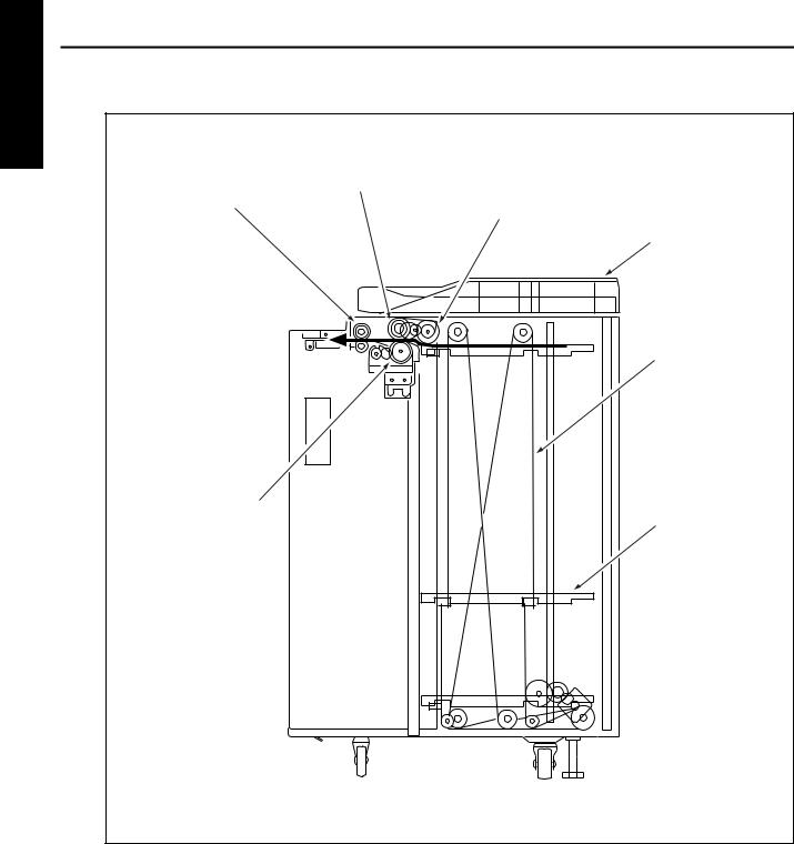
CENTER CROSS-SECTIONAL DRAWING
Feed roller
Conveyance roller
Paper feed roller
Top cover
Up/down wire (the other side wire as well)
Double feed
prevention roller
Up/down plate
1-2
C-403/C-404
DRIVE SYSTEM DRAWING
[1] Paper feed drive section
Feed roller
LT First paper feed SD (SD100)
Paper feed roller
FRONT
LT paper feed motor (M101)
LT First paper feed MC (MC 102) 
Conveyance roller
LT feed drive MC (MC101)
Double feed
prevention roller |
Paper feed roller |
FRONT |
|
Feed roller |
|
1 OUTLINE
1-3
1 OUTLINE
C-403/C-404
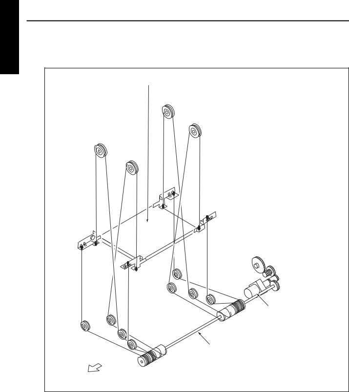
[2] Stacked paper up/down wire drive section
a.C-403
Up/down plate
LT up/down motor (M100)
Up/down shaft
FRONT
1-4
|
|
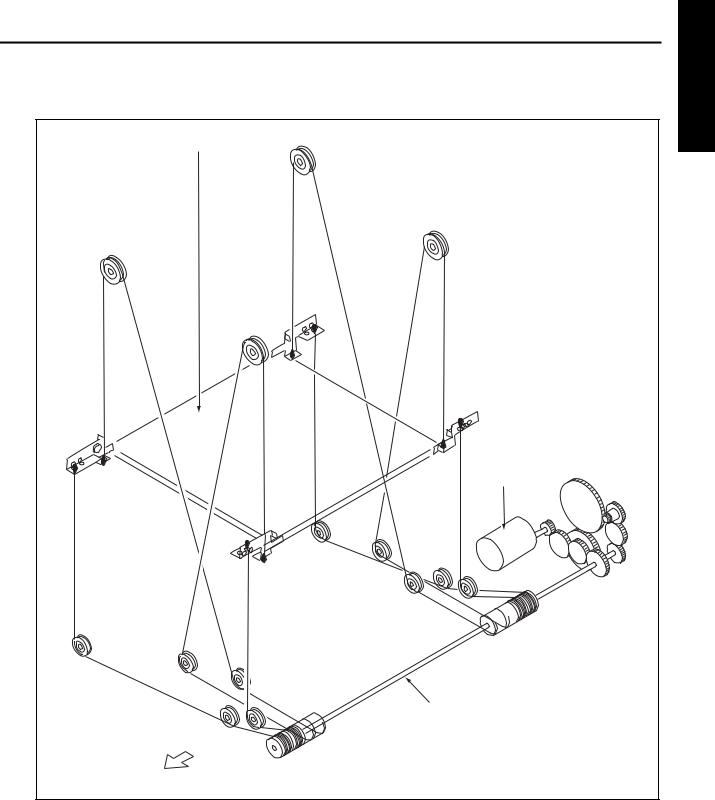
C-403/C-404 |
b. |
C-404 |
1 OUTLINE |
|
|
Up/down plate |
|
|
LT up/down motor |
|
|
(M100) |
|
|
Up/down shaft |
|
|
FRONT |
|
|
1-5 |

1 OUTLINE
Blank page

2
UNIT EXPLANATION
2 UNIT EXPLANATION

2 UNIT EXPLANATION
Blank page
C-403/C-404
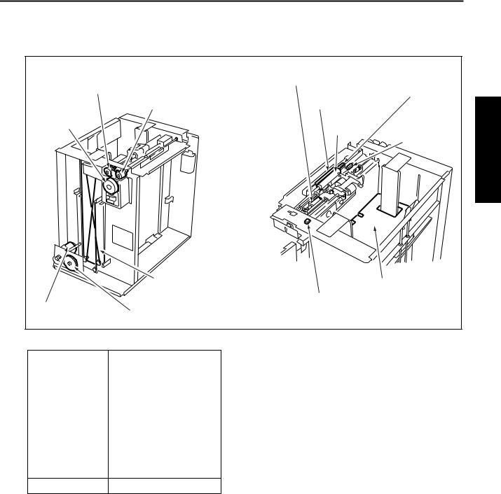
PAPER FEED SECTION
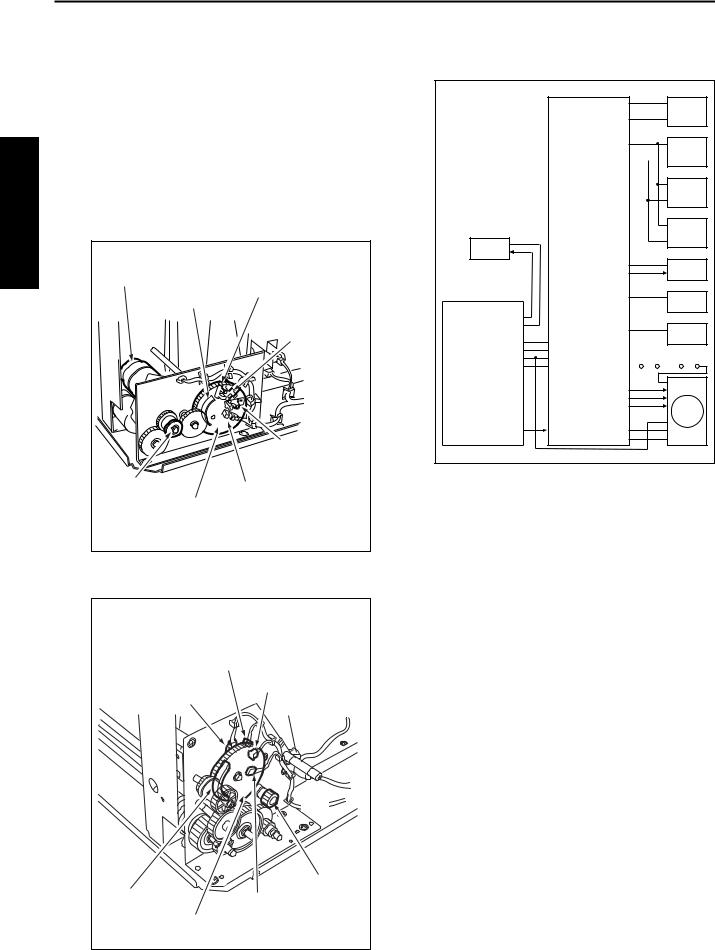
[1] Composition
LT feed MC (MC101)
LT paper |
LT first paper feed MC (MC102) |
feed motor |
|
(M101) |
|
|
Up/down wire |
|
|
(the other side wire as well) |
|
LT up/down motor |
Remaining paper detection gear |
|
(M100) |
||
|
LT first paper feed SD |
|
(SD100) |
|
Paper dust |
LT feed PS (PS106) |
removing brush |
|
Conveyance
roller LT first paper feed PS (PS107)
Up/down plate
LT tray down drive switch (SW 100)
[2] Mechanisms |
*2 Remaining paper detection |
Mechanism |
Method |
Paper lifting *1 |
Wire drive |
|
|
Paper feed |
Paper feed roller |
|
|
No paper detection Photo sensor (PS108) |
|
|
+actuator |
|
|
Remaining paper |
Remaining paper detec- |
detection *2 |
tion gear+ photo sensor |
|
(PS102, PS103, PS104, |
|
PS105) |
Paper conveyance Roller conveyance
The LCT is equipped with a remaining paper detection gear which rotates together with LT up/ down motor (M100) driving the up/down plate.
The remaining paper detection gear has an actuator to turn ON/OFF LT remaining paper detection PS1 (PS102), LT remaining paper detection PS2 (PS103), LT remaining paper detection PS3 (PS104), and LT remaining paper detection PS4 (PS105).
*1 Paper lifting
a.Up/down plate lifting drive operation
The up/down plate is lifted with the up/down wires. When the top cover closes, LT up/down motor (M100) rotates and the up/down plate connected to the up/down wires rises.
b.Up/down plate down drive operation
The up/down plate automatically lowers by 120 mm when the top cover is opened. Subsequently, it is lowered by 120 mm each time LT tray down drive switch (SW100) is pressed.
2 UNIT EXPLANATION
2-1
2 UNIT EXPLANATION
C-403/C-404
Each sensor is turned ON/OFF according to the rotating position of the remaining paper detection gear and since this is linked with the up/down position of the up/down plate, the remaining paper quantity in the LCT can be determined by monitoring the ON/OFF of each sensor. The remaining paper quantity detected with the four sensors is displayed on the main body display.
a.C-403
LT remaining paper LT up/down motor (M100) detection PS1
(PS102)
Actuator |
LT remaining |
|
|
|
paper detection |
|
PS2 (PS103) |
|
LT remaining |
|
|
paper detection |
|
Gear for M100 |
PS3 (PS104) |
|
LT remaining paper |
||
|
||
Remaining |
detection PS4 (PS105) |
|
paper detection |
|
|
gear |
|
b.C-404
LT remaining paper detection
PS2 (PS103)
LT remaining paper
LT remaining paper detection PS3 (PS104) detection PS1 (PS102)
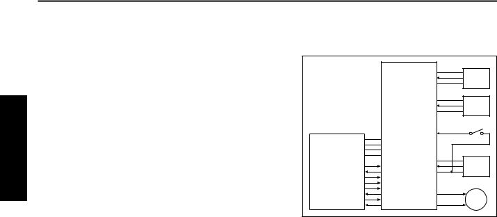
[3] First paper feed control
HTR101
MAIN BODY
24V PGND 5V SGND
IO_DTXD 
IO_UCLK 
LCT_LATCH 
IO_DCLK 
ERR_OUT4 
IO_URXD 
ACK4
REQ4 
5V
LT DB UPOP_PS  PS100
PS100
S_GND
5V
CONV_PS  PS106 S_GND
PR_PS  PS107
PS107
SIDOP_PS  PS110
PS110
24V |
MC101 |
|
CONT |
||
|
24V
CONT  MC102
MC102
24V
CONT  SD100
SD100
MS101 MS102
24V 

LCTM_CONT
LCTM_CLK
LCTM_F/R
LCTM_EM  M101 5V
GND P_GND
The first paper is fed by the paper feed roller and the feed roller driven by M101(LT paper feed) via MC101(LT feed MC). The paper feed roller and feed roller touche the paper when SD100 (LT first feed) is ON, feeding the paper to the conveyance roller. Then, SD100 (LT first paper feed) turns OFF to release the paper feed roller and feed roller from the paper. The conveyance roller is also driven by M101, by turning ON MC102 (LT first feed MC), paper is fed to the main body.
The related signals are: PS100 (LT top cover open/close detection), PS106 (LT feed), PS107 (LT first feed), and PS110 (LT jam access door open/close detection).
Gear for M100 Actuator LT remaining paper
Remaining paper detection PS4 (PS105) detection gear
2-2

C-403/C-404
1. Operation
a.First paper feed timing
(1) Start of first paper feed
At predefined interval after the START button is pressed.
(2) Start of second and subsequent papers
When PS106 (LT feed) is turned OFF by the preceding paper.
(3) OFF timing
When the main body M7 (paper exit) turns OFF.
b.Interlock
The power supply line of M101 (LT paper feed) is equipped with MS101 (LT interlock/1) and MS102 (LT interlock/2). When the top cover is opened, MS101 turns OFF, and when the jam access door is opened MS102 turns OFF, thereby cutting off the power supply to M101.
Furthermore, the top cover is equipped with PS100 (LT top cover open/close detection) and the jam access door is equipped with PS110 (LT jam access door open/close detection) and when either of these doors is opened during paper feed, the M101 drive signal is turned OFF to stop the paper feed operation.
c.Internal heater
The LCT is equipped with HTR101 (LT internal heater) to protect the paper from humidity. HTR101 is directly controlled by the main body PRCB (printer control board) rather than by the LTDB (LT drive board).
2. Signals
a.Input signals
(1)UPOP_PS (PS100 to LTDB)
Top cover open/close detection signal [L]: Cover opened
[H]: Cover closed
(2)CONV_PS (PS106 to LTDB)
Conveyance roller exit paper detection signal [L]: Paper detected
[H]: Paper not detected
(3)PR_PS (PS107 to LTDB)
Conveyance roller entrance (pre-registration position) paper detection signal
[L]: Paper detected [H]: Paper not detected
(4)SIDOP_PS (PS110 to LTDB)
Jam access door open/close detection signal [L]: Door opened
[H]: Door closed
(5)LCTM_EM (M101 to LTDB)
M101 rotation error detection signal [L]: M101 rotating
[H]: M101 not rotating
(6)IO_DTXD (MAIN BODY to LTDB)
Serial data to transmit main body PRCB (printer control board) operating status to LTDB
(7)LCT_LATCH (MAIN BODY to LTDB) IO_DTXD signal latch signal
(8)IO_DCLK (MAIN BODY to LTDB) IO_DTXD signal clock signal
(9)ERR_OUT4 (MAIN BODY to LTDB)
Signal to notify LTDB (LT drive board) when there is error in the main body
(10)ACK4 (MAIN BODY to LTDB)
Serial data transmission enable signal from LCT to main body PRCB (printer control board)
2 UNIT EXPLANATION
2-3
2 UNIT EXPLANATION
C-403/C-404
b.Output signals
(1)CONT (LTDB to MC101)
MC101 (LT feed MC) ON/OFF drive signal [L]: MC101 ON
[H]: MC101 OFF
(2)CONT (LTDB to MC102)
MC102 (LT first paper feed MC) ON/OFF drive signal
[L]: MC102 ON [H]: MC102 OFF
(3)CONT (LTDB to SD100)
SD100 ( LT first paper feed) ON/OFF drive signal [L]: SD100 ON
[H]: SD100 OFF
(4)LCTM_CONT (LTDB to M101)
M101 (LT paper feed) ON/OFF control signal [L]: M101 ON
[H]: M101 OFF
(5)IO_URXD (LTDB to MAIN BODY)
Serial data to transmit the LTDB (LT drive board) operating status to main body PRCB
(6)IO_UCLK (LTDB to MAIN BODY) IO_URXD signal clock signal
(7)REQ4 (LTDB to MAIN BODY)
Serial data send request signal from LCT to main body PRCB
(8)LCTM_CLK (M101 to LTDB)
M101 (LT paper feed) rotational speed control clock signal
(9)LCTM_F/R (M101 to LTDB)
M101 (LT paper feed) rotational direction indication signal
This machine always indicates [H]: normal rotation.
[4] Up/down plate drive control
|
|
LT DB |
|
|
|
5V |
PS100 |
|
|
UPOP_PS |
|
|
|
S_GND |
|
|
|
5V |
PS101 |
|
|
SIG |
|
|
|
S_GND |
|
|
|
|
SW100 |
MAIN BODY |
|
DW_SW |
|
24V |
|
|
|
|
PGND |
|
|
|
5V |
|
|
|
SGND |
|
|
|
|
5V |
PS109 |
IO_DTXD |
UP_PS |
||
IO_UCLK |
S_GND |
|
|
LCT_LATCH |
|
|
|
IO_DCLK |
|
|
|
ERR_OUT4 |
|
|
|
IO_URXD |
D1 |
M100 |
|
|
ACK4 |
D2 |
|
|
REQ4 |
|
|
When the top cover opens or closes, M100 (LT up/down motor) rotates forward or backward to move the up/down plate up or down. The up/ down plate descends by 120 mm each time SW100 (LT tray down drive) is pressed while the top cover is opened.
The related signals are PS100 (LT top cover open/close detection), PS101 (LT lower limit detection), and PS109 (LT upper limit detection).
1. Operation
a. Up/down plate descend timing
(1)ON timing
When the top cover is opened and PS100 (LT top cover open/close detection) is turned OFF, M100 rotates backward to lower the up/down plate.
When SW100 (LT tray down drive) turns ON by pressing, M100 rotates backward to move the up/down plate down.
(2)OFF timing
M100 turns OFF at predefined interval after PS100 turns OFF or SW100 turns ON. This in turn lowers the up/down plate by 120 mm.
(3)Others
The up/down plate descends by 120 mm each time SW100 is pressed until PS101 turns ON to indicate the bottom limit of the up/down plate.
2-4
C-403/C-404
b. Up/down plate ascend timing
(1)ON timing
When the top cover is closed and PS100 (LT top cover open/close detection) is turned ON, M100 (LT UP/DOWN) rotates forward to raise the up/ down plate.
(2)OFF timing
When the up/down plate rises and PS109 (LT upper limit detection) turns ON to indicate the detection of the topmost paper, M100 (LT UP/ DOWN) turns OFF and stops the up/down plate. The up/down plate also stops when the top cover is opened and PS100 (LT top cover open/ close detection) turns OFF.
2. Signals
a.Input signals
[5]Remaining paper detection/No paper detection control
|
|
LT DB |
|
|
|
|
5V |
PS102 |
|
|
|
SIG |
|
|
|
|
S_GND |
|
EXPLANATION |
|
|
5V |
PS103 |
|
|
|
SIG |
||
|
|
S_GND |
|
|
|
|
5V |
PS104 |
|
|
|
SIG |
||
|
|
S_GND |
|
|
|
|
|
|
|
MAIN BODY |
|
5V |
PS105 |
UNIT |
24V |
SIG |
|||
|
PGND |
S_GND |
|
|
|
5V |
|
|
|
|
SGND |
|
|
2 |
|
|
5V |
PS108 |
|
|
|
|
||
IO_DTXD |
0_PS |
|
||
IO_UCLK |
S_GND |
|
|
|
LCT_LATCH |
|
|
|
|
IO_DCLK |
|
|
|
|
ERR_OUT4 |
|
|
|
|
IO_URXD |
D1 |
M100 |
|
|
|
ACK4 |
D2 |
|
|
|
REQ4 |
|
|
|
(1)SIG (PS101 to LTDB)
Up/down plate lower limit detection signal [L]: Up/down plate not at lower limit [H]: Up/down plate at lower limit
(2)UP_PS (PS109 to LTDB)
Up/down plate upper limit detection signal [L]: Up/down plate not at upper limit [H]: Up/down plate at upper limit
(3)DW_SW (SW100 to LTDB)
SW100 (LT tray down switch) ON/OFF detection signal
[L]: SW100 ON [H]: SW100 OFF
b.Output signal
(1)D1, 2 (LTDB to M100)
M100 (LT UP/DOWN) drive signal
These signals switches the direction of the drive current to control the rotation direction of M100.
The remaining paper quantity is detected by PS102 (LT remaining paper detection 1), PS103 (LT remaining paper detection 2), PS104 (LT remaining paper detection 3), and PS105 (LT remaining paper detection 4) and no paper detection is made by PS108 (LT no paper detection).
The signals detected by these sensors are controlled by LTDB (LT drive board) and displayed on the main body display.
1. Operation
a.Remaining paper detection control
The remaining paper quantity is determined from the ON/OFF combination of sensors PS102 (LT remaining paper detection 1), PS103 (LT remaining paper detection 2), PS104 (LT remaining paper detection 3), and PS105 (LT remaining paper detection 4) which detect the rotational position of M100 (LT UP/DOWN) that is driving the up/down plate. Each sensor turns ON or OFF according to the position of the remaining paper detection gear which is linked with the rotation of M100.
The remaining paper quantity is detectable at eight levels, but it is displayed on the main body display as five levels.
2-5

C-403/C-404
|
|
<Remaining paper quantity and display> |
||||||
|
|
|
|
|
|
|
|
|
|
|
Stacked |
|
|
|
|
Remaining |
|
|
|
paper |
PS102 |
PS103 |
PS104 |
PS105 |
paper quantity |
|
|
|
quantity |
|
|
|
|
display |
|
|
|
|
|
|
|
|
|
|
|
|
0 to 700 |
OFF |
OFF |
OFF |
OFF |
1 flashing |
|
EXPLANATION |
||||||||
|
|
|
|
|
|
|
||
|
701 to 1200 |
ON |
OFF |
OFF |
OFF |
1 on |
||
|
|
|||||||
|
|
|
|
|
|
|
|
|
|
|
1201 to 1700 |
ON |
ON |
OFF |
OFF |
2 on |
|
|
|
|
|
|
|
|
|
|
|
|
1701 to 2200 |
ON |
ON |
ON |
OFF |
2 on |
|
|
|
|
|
|
|
|
|
|
|
|
2201 to 2700 |
ON |
ON |
ON |
ON |
3 on |
|
|
|
|
|
|
|
|
|
|
UNIT2 |
|
2701 to 3200 |
OFF |
ON |
ON |
ON |
3 on |
|
|
|
|
|
|
|
|
||
|
3201 to 3700 |
OFF |
OFF |
ON |
ON |
4 on |
||
|
|
|||||||
|
|
|
|
|
|
|
|
|
|
|
3701 or more |
OFF |
OFF |
OFF |
ON |
4 on |
|
|
|
|
|
|
|
|
|
|
Caution:The remaining paper quantity is indicated on the control panel with four horizontal bars. Stacked paper quantity differs depending on the thickness of the paper.
b.No paper detection control
When there is no more paper inside the LCT, PS108 (LT no paper detection) turns ON and a message is displayed on the main body display.
2. Signals
a.Input signals
(1)SIG (PS102 to LTDB)
Remaining paper detection gear rotational position detection signal
[L]: PS102 OFF [H]: PS102 ON
(2)SIG (PS103 to LTDB)
Remaining paper detection gear rotational position detection signal
[L]: PS103 OFF [H]: PS103 ON
(3)SIG (PS104 to LTDB)
Remaining paper detection gear rotational position detection signal
[L]: PS104 OFF [H]: PS104 ON
(4)SIG (PS105 to LTDB)
Remaining paper detection gear rotational position detection signal
[L]: PS105 OFF [H]: PS105 ON
(5)0_PS (PS108 to LTDB)
LCT no paper detection signal [L]: No paper
[H]: Paper present
2-6

3
DISASSEMBLY/ASSEMBLY
3 DIS./ASSEMBLY

3 DIS./ASSEMBLY
This section explains how to disassemble and reassemble the machine. When disassembling and reassembling the machine, follow the precautions given below.
1.Be sure the power cord has been unplugged from the wall outlet.
2.The disassembled parts must be reassembled following the disassembly procedure in reverse unless otherwise specified.
3.Care should be taken not to lose small parts. Care should also be taken not to install small parts in wrong places.
4.Do not operate the machine before installing all the disassembled parts completely.
5.Removal of some screws is prohibited in this section. Never loosen them.
C-403/C-404
PAPER FEED SECTION
[1]Cleaning the Paper Dust Removing Brush
 Caution:If LT is connected to the main body, make sure that main body power plug is disconnected from the power outlet.
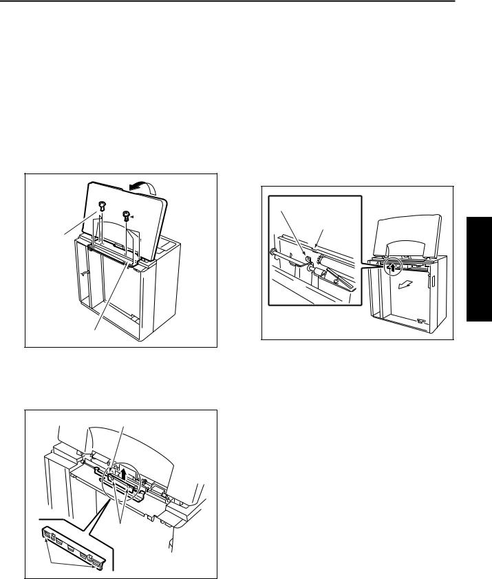
a.Procedure
(1)Open the top cover.
(2)Remove six screws to detach the paper feed cover B.
Top  cover
cover 
 Screws
Screws
Paper feed cover B
[2]Cleaning the LT feed PS (PS106)/LT first paper feed PS (PS107)
 Caution:If LT is connected to the main body, make sure that main body power plug is disconnected from the power outlet.
a.Procedure
(1)Looking into the paper exit side of the LCT from below, and clean sensors through the cavity for LT feed PS (PS106) and the cavity for LT first paper feed (PS107) using a blower brush.
Cavity for PS106 |
|
Cavity for PS107 |
3 DIS./ASSEMBLY |
Paper |
|
exit |
|
side |
|
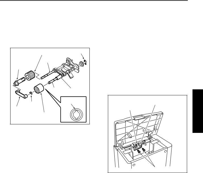
(3)Insert a flat bladed screwdriver in the cavities (in two locations) for paper dust removing brush to release the locking lugs, then remove the paper dust removing brush.
Paper dust removing brush |
Cavity |
Locking lugs |
(4)Clean the paper dust removing brush using a blower brush.
(5)Reinstall the above parts following the removal steps in reverse.
3-1

C-403/C-404
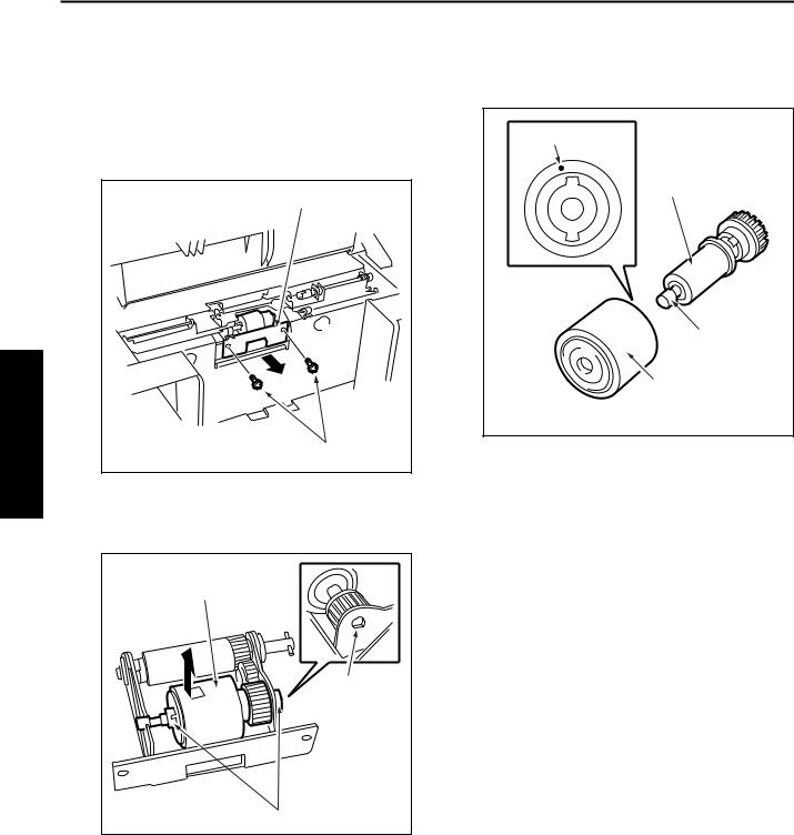
[3]Removing and Reinstalling the Paper Feed Roller Unit
 Caution:If LT is connected to the main body, make sure that main body power plug is disconnected from the power outlet.
a.Procedure
(1)Open the top cover.
(2)Remove the spring from the paper feed roller unit.
|
Top cover |
DIS./ASSEMBLY |
Spring |
Paper feed roller unit |
|
|
Remove |
|
this. |
3 |
|
|
Paper feed roller unit |
(3)After removing two stop rings, remove the two bearings outward to remove the paper feed roller unit.
Paper feed roller unit |
|
Bearing |
Bearing |
|
|
Stop ring |
Stop ring |
[4]Replacing the Paper Feed Roller Rubber/Feed Roller Rubber
 Caution:If LT is connected to the main body, make sure that main body power plug is disconnected from the power outlet.
a.Procedure
(1)Remove the paper feed roller unit.
(2)Remove the bearing and paper feed reference actuator.
Paper feed reference actuator |
Bearing |
(3)Remove two stop rings.
(4)Remove two bearings outward to detach the roller section from the roller fitting.
Roller fitting |
Bearing |
|
|
Stop rings |
|
Bearing |
|
(4)Reinstall the above parts following the removal steps in reverse.
3-2
C-403/C-404
(5)Remove the bearing from the opposite side of the coupling, then remove the paper feed roller from the shaft.
(6)Remove the stop ring to pull the feed roller from the shaft.
(7)Remove the rubber from each roller.
Paper feed roller rubber |
Coupling |
|
|
||
Shaft |
|
|
Paper feed |
|
|
roller |
|
|
Shaft |
|
Feed roller |
Stop ring |
Paint mark |
|
Bearing |
|
|
Feed roller rubber |
|
|
(8)Reinstall the above parts following the removal steps in reverse.
Caution1: Make sure rollers and rubber portions are oriented properly when reinstalling them.
Caution2: Make sure the one-way clutch direction is correct.
Caution3: Check whether grease or the like is present on each roller.
[5]Replacing the Double Feed Prevention Roller Rubber
 Caution:If LT is connected to the main body, make sure that main body power plug is disconnected from the power outlet.
a.Procedure
Caution: With the power held on, press the LT tray down switch (SW100) to move the up/down plate down to the bottom in advance.
(1)Remove the paper feed roller unit.
(2)Remove two screws to detach the double feed prevention roller unit cover.
|
Double feed |
Double feed |
prevention roller unit cover |
prevention roller |
|
Screws
3 DIS./ASSEMBLY
3-3
3 DIS./ASSEMBLY
C-403/C-404
(3) Remove two screws to detach the double feed |
(5) Remove the double feed prevention roller rubber |
prevention roller unit. |
from the double feed prevention roller. |
Caution: When reinstalling the double feed prevention roller unit, tighten the screws on the rear side first.
Double feed prevention roller unit |
|
Screws |
(6) |
|
(4)Remove two stop rings, fit the shaft into the D-cut in the fitting, and remove the double feed prevention roller together with the shaft.
Double feed prevention roller |
D-cut |
Stop ring |
Paint mark |
Double feed |
prevention roller |
Shaft |
Double feed |
prevention roller |
rubber |
Reinstall the double feed prevention roller in the reverse order of the removal procedure. Caution1: Make sure the double feed preven-
tion roller rubber is oriented properly when reinstalling it.
Caution2: Check whether scratch or the like is visible on the pet cover for the drive gear.
Caution3: Check whether grease or the like is present on double feed prevention roller.
3-4
C-403/C-404
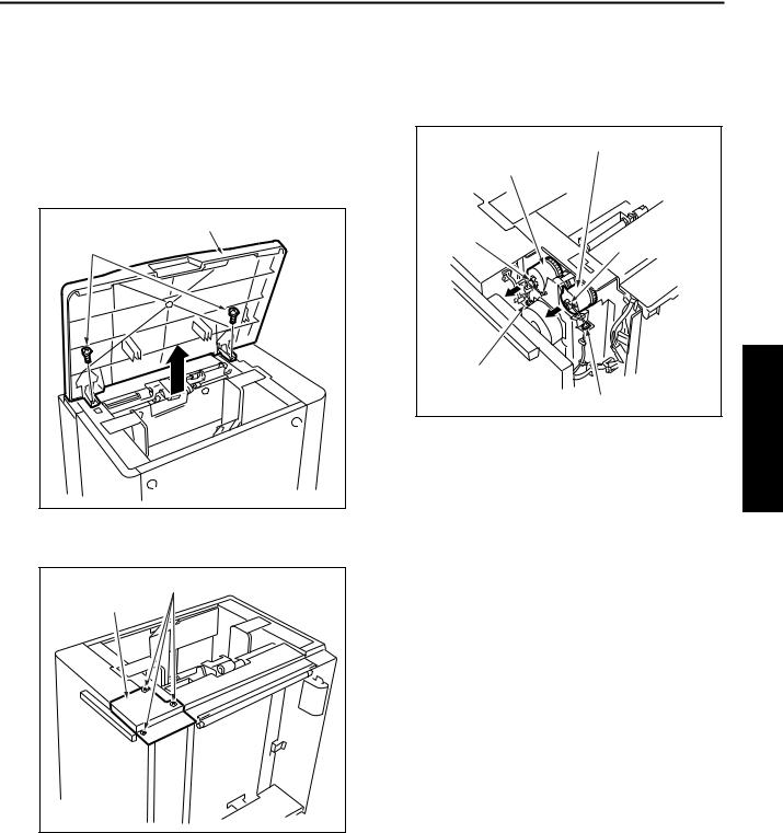
[6] Replacing the LT feed MC (MC101)/LT first paper feed MC (MC102)
a.Procedure
(1)Open the top cover.
(2)Remove the spring from the paper feed roller unit.
(3)Remove two screws to detach the top cover.
Top cover |
Screws |
(4) Remove three screws to detach the clutch |
replacement cover. |
Clutch |
Screws |
|
|
replacement cover |
|
(5)Disconnect two relay connectors (CN765, CN766) of the clutches.
(6)Remove the stop ring to detach each clutch.
LT first paper feed MC (MC102)
LT feed MC (MC101)
Stop ring
Stop ring
Relay connector
(CN766)
Relay connector (CN765)
(7)Reinstall the above parts following the removal steps in reverse.
Caution: When installing each MC, make sure that the stopper of each clutch is on the predefined position.
3 DIS./ASSEMBLY
3-5
3 DIS./ASSEMBLY
C-403/C-404
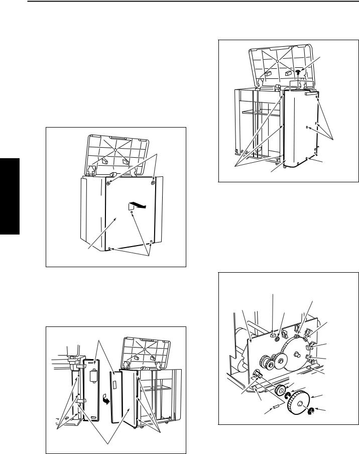
[7] Replacing the C-403 Up/Down Wires
Caution: With the power held on, press the LT tray down switch (SW100) to move the up/down plate down to the bottom in advance.
a.Procedure
(1)Open the top cover.
(2)Remove the clutch replacement cover.
(3)Remove five screws to detach the right side cover.
Screws
Right side |
|
cover |
Screws |
(5) Remove twelve screws to detach the rear cover.
Screw
 Screws
 Screws
Screws
Rear cover
(6)Remove the five relay connectors (CN749, CN780, CN781, CN782, CN783) to disconnect the wiring harness from the up/down motor mounting assembly.
(7)Remove the E-ring to detach the up/down gear.
(8)Pull the pin from the shaft.
(9)Remove the E-ring to detach the bearing.
(10)Remove three screws to detach the up/down motor assembly.
(4) |
After opening the jam access door, remove six |
|
Relay connector |
Relay |
|
screws to detach the front cover. |
|
||
|
Up/down |
(CN749) |
connector |
|
|
|
|||
|
Caution: When removing the front cover, close |
motor mounting |
(CN780) |
|
|
Relay |
|||
|
the jam access door after removing |
assembly |
Screw |
|
|
|
connector |
||
|
the screws. |
|
|
|
|
|
|
(CN781) |
|
|
|
|
|
Relay |
|
Jam access door |
|
|
connector |
|
|
|
|
(CN782) |
|
|
|
|
Relay |
|
|
|
|
connector |
|
|
|
|
(CN783) |
|
|
|
|
Screw |
|
|
|
Bearing |
|
|
|
|
|
E-ring |
|
|
Shaft |
|
Up/down |
|
|
Screw |
gear |
|
|
|
|
||
|
|
|
Pin |
E-ring |
|
|
|
|
|
|
Screws |
|
|
|
|
Screws |
|
|
|
|
Right side cover |
|
|
|
3-6
 Loading...