


 Loading...
Polygon Editing Tool
Instruction Manual

ν Safety Symbols
The following symbols are used in this manual to prevent accidents which may occur as result of incorrect use of the instrument.
Denotes a sentence regarding safety warning or note.
Read the sentence carefully to ensure safe and correct use.
Denotes a prohibited operation.
The operation must never been performed.
Denotes an instruction.
The instruction must be strictly adhered to.
Denotes a sentence regarding safety precaution for laser.
Read the sentence carefully to ensure safe and correct use.
ν Notes on this Manual
• The VI-9i, VI-910, VI-900, VI-700, VI-300 are model names for Europe and VIVID 9i, VIVID 910, VIVID 900, VIVID 700, VIVID 300 are model names for other countries. The VIVID (VI) series digitizer includes VIVID 9i (VI-9i), VIVID 910 (VI-910), VIVID 900 (VI-900), VIVID 700 (VI-700) and VIVID 300 (VI-300).
• In this manual, VIVID(VI) Series digitizer is also renamed to as “VIVID digitizer” or simply “VIVID”.
• Copying or reproduction of all or any part of the contents of this manual without KONICA MINOLTA SENSING’s permission is strictly prohibited.
• The contents of this manual are subject to change without prior notice.
• Every effort has been made in the preparation of this manual to ensure the accuracy of its contents. However,should you have any questions or find any errors,please contact a KONICA MINOLTA SENSING authorized service facility.
• KONICA MINOLTA SENSING will not accept any responsibility for consequences arising from the use of the instrument.
ν Trademarks
• Microsoft and Windows are registered trademarks of the Microsoft Corporation in the United States and other countries.
• Other product names and company names used herein are trademarks or registered trademarks of their respective owners.
ν Official names for application mentioned in this manual
Name given in this manual |
Official name |
Windows |
Microsoft® Windows® |
Windows XP |
Microsoft® Windows® XP Professional Operating System |
Windows Vista |
Microsoft® Windows® Vista Business Operating System |
Windows 7 |
Microsoft® Windows® 7 Professional Operating System |
ν About This Manual and Related Documents
This manual explains how to install and operate the Polygon Editing Tool software as well as explaining all the functions it provides.
The Polygon Editing Tool software is designed to control “VIVID Series” non-contact 3D digitizers, convert scan data into polygons, edit data and convert VIVID data to universal data formats.
The following is a list of manuals related to this one.
Document |
Content |
Polygon Editing Tool
Explains the basic operations of the Polygon Editing Tool software.
Basic Operation Guide
Instruction manual for each model in |
VIVID digitizers offers rapid, high-precision 3D scanning ideal for imaging of in- |
the VIVID series of non-contact 3D |
dustrial products in a wide range of shapes and configurations. This manual describes the |
digitizers |
digitizer’s features and operating procedures, and calls attention to relevant precautions. |
|
|
Photogrammetry System |
Explains the PSC-1 system, a high-precision alignment system based on photographic |
PSC-1 Instruction Manual |
measurement technology. This system is for use in the VIVID 9i only. |
|
|
Bench Top Frame Set |
This manual explains how to set up the Bench Top Frame Set, which offers more |
stable measurements both horizontally and vertically, and how to attach the VIVID |
|
Instruction Manual |
910(VI-910) or VIVID 900(VI-900) to the set. This frame set is for use with VIVID |
|
910(VI-910) or VIVID 900(VI-900) only. |
|
|
Safety Precautions
When using this software, the following points must be strictly observed to ensure correct and safe use. After you have read this manual, keep it in a safe place so that it can be referred to easily whenever it is needed.
WARNING |
Failure to adhere to the following points may |
result in death or serious injury |
To ensure correct and safe use of this software, please read the instruction manuals of the VIVID (VI) series digitizer and personal computer in addition to this manual before operating. Incorrect operation of the software may result in fire or electric shock.
Software Restrictions
•Copying or reproduction of all or any part of the contents of this software and manual without KONICA MINOLTA SENSING’s permission is strictly prohibited.
•The specifications of the software are subject to change without prior notice.
•KONICA MINOLTA SENSING will not take any responsibility for damage caused as result of use of this software.
Notes On Use
•When inserting a CD-ROM into the CD-ROM drive, make sure that it is placed straight in the right direction, and inserted gently.
•Keep the CD-ROM clean. If it becomes dirty, a reading or writing error may result.
•Pay attention to rapid temperature changes and dew condensation.
•Keep the CD-ROM away from direct sunlight or heaters.
•Do not let the CD-ROM drop or be exposed to strong shocks.
•Keep the CD-ROM away from water, alcohol, thinner etc.
Notes On Storage
• Do not store the CD-ROM in a hot area, for instance, in direct sunlight or near heaters.
1

Contents |
|
|
|
|
|
Safety Precautions............................................................................................................................................... |
|
|
|
1 |
|
Software Restrictions........................................................................................................................................... |
|
|
|
1 |
|
Notes On Use....................................................................................................................................................... |
|
|
|
1 |
|
Notes On Storage................................................................................................................................................ |
|
|
|
1 |
|
Conventions for Command Reference (Chapter 2) |
.............................................................................................. |
6 |
|||
Chapter 1 Foreword |
|
|
|
||
Preparations |
|
|
|
|
|
1) Introduction of Operating Conditions......................................................................................................................... |
|
8 |
|||
2) Attaching the protect key to the computer................................................................................................................... |
|
9 |
|||
3) Installing the ASPI driver software on the computer.................................................................................................. |
10 |
||||
4) Installing Polygon Editing Tool on the computer........................................................................................................ |
|
11 |
|||
5) Connecting the VIVID (VI) digitizer to the computer .......(necessary only if the VIVID (VI) digitizer will be controlled from the software) |
13 |
||||
Regarding the software |
|
|
|
||
1) Starting and exiting from the software........................................................................................................................ |
|
16 |
|||
2) Main window, toolbar and icons |
................................................................................................................................. |
|
17 |
||
Uninstalling |
|
|
|
|
|
1) Uninstalling Polygon Editing Tool............................................................................................................................... |
|
19 |
|||
2) Uninstalling the protect key (HASP) ...................................................................................................driver software |
20 |
||||
Chapter 2 Command Reference |
|
|
|||
• File Menu |
|
|
|
|
|
File |
New |
|
|
Creating New Scene Data |
24 |
|
Open |
|
|
Opening Saved Data |
24 |
|
Save |
Elements |
|
Saving Element Data |
26 |
|
|
Scene |
|
Saving Scene Data |
27 |
|
Save as |
Elements |
|
Saving Element Data under a Different Name |
28 |
|
|
Scene |
|
Saving Scene Data under a Different Name |
29 |
|
Import |
Elements |
|
Importing Scanned Data |
30 |
|
Import |
Digitizer |
One Scan |
|
|
|
|
|
|
Performing One Scan with the VIVID 9i |
33 |
|
|
|
|
Performing One Scan with the VIVID 910 |
50 |
|
|
|
|
Performing One Scan with the VIVID 900 or VIVID 910 |
74 |
|
|
|
|
Performing One Scan with the VIVID 700 |
103 |
|
|
|
|
Performing One Scan with the VIVID 300 |
118 |
|
Import |
Digitizer |
Step Scan |
|
|
|
|
|
|
Performing Step Scan with the VIVID 9i |
41 |
|
|
|
|
Performing Step Scan with the VIVID 910 |
58 |
|
|
|
|
Performing Step Scan with the VIVID 900 or VIVID 910 |
79 |
|
|
|
|
Performing Step Scan with the VIVID 700 |
106 |
|
|
|
|
Performing Step Scan with the VIVID 300 |
121 |
|
Import |
Digitizer |
PC Card |
|
|
|
|
|
|
Importing Data from the Memory Card of VIVID 910 |
67 |
|
|
|
|
Importing Data from the Memory Card of VIVID 900 or VIVID 910 |
96 |
|
|
|
|
Importing Data from the Memory Card of VIVID 700 |
111 |
|
|
|
Easy Align |
Aligning Multiple Scans (for VIVID 910 only) |
126 |
|
|
|
PSC - 1 |
Performing Precision Registration of Scan Data |
136 |
|
Export |
Elements |
|
Exporting Element Data as Various Formats |
137 |
|
|
Images |
|
Exporting Image Data as Various Formats |
140 |
|
|
Elements |
|
Removing the Selected Element (s) |
141 |
|
Preferences |
|
|
Displaying Information for Setting Conditions |
142 |
|
Select Digitizer |
|
Selecting a Digitizer |
144 |
|
|
Exit |
|
|
Exiting the Polygon Editing Tool |
145 |
2

• View Menu
View |
Orbit |
Rotating or moving the Camera Position |
148 |
|
Zoom |
Enlarging/Reducing the Displayed Item |
149 |
|
|
|
|
|
Full Frame All |
Displaying Data Fully in all Windows |
150 |
|
Full Frame Displaying |
Data Fully in Active Window |
150 |
|
|
|
|
|
Area Orbit |
Rotating the Camera and Setting the Rotation Center |
151 |
|
Area Zoom |
Enlarging/Reducing Item Enclosed by Specified Rectangle |
152 |
|
|
|
|
|
Move Plane |
Setting Display Depth |
153 |
|
Move Light |
Moving the Light |
154 |
|
|
|
|
|
Camera Settings |
Setting the Camera Parameters |
155 |
|
Image |
Displaying Color Images |
156 |
|
|
|
|
|
Show Element List/Hide Element List |
Displaying/Hiding the Element List |
156 |
|
Show Toolbar |
Displaying the Toolbar |
156 |
• Select Menu |
|
|
|
|
|
|
|
Select |
Point |
Selecting/Unselecting a Point by Clicking the Mouse |
158 |
|
Rectangle |
Selecting/Unselecting Points within Specified Rectangle Area |
159 |
|
|
|
|
|
Bezier |
Selecting Points within Specified Bezier Curve |
160 |
|
Boundary – Elements |
Selecting Only the Boundary of Holes of Element (s) |
162 |
|
|
|
|
|
Boundary – Points |
Selecting Only the Boundary of Holes of Points |
162 |
|
Color |
Selecting Points within Specified Homogeneous Area |
163 |
|
|
|
|
|
Toggle Points |
Reversing Selection State of Points of Selected Element (s) |
165 |
|
Select by Elements |
Selecting All the Points of Element (s) |
165 |
|
|
|
|
|
Unselect by Elements |
Unselecting All the Points of Element (s) |
166 |
|
Select Front |
Selecting Only the Points Comprising Polygons that are Both Visible and at the Front |
166 |
• Edit Menu |
|
|
|
|
|
|
|
Edit |
Undo |
Canceling the Previous Operation |
168 |
|
Redo |
Performing the Canceled Operation |
168 |
|
|
|
|
|
Delete – Elements |
Deleting the Selected Elements from the Element List |
169 |
|
Delete – Points |
Deleting the Selected Points |
170 |
|
|
|
|
|
Delete – Polygons |
Deleting Polygons Comprised of Selected Points |
170 |
|
Images |
Editing the Texture of Selected Element |
171 |
|
|
|
|
|
Define |
Defining Points as a New Element |
178 |
|
Recalc LOD |
Recalculating the Simplified Display Data |
179 |
Chapter 1
Preparations
Regarding the software
Uninstalling
Chapter 2
File
Menu
View
Menu
Select
Menu
Edit
Menu
Build
Menu
Info
Menu
Window
Menu
Tool
Menu
Pop-up Menus
in Element View
Window
Pop-up Menus
in Element List
Pop-up Menus
in Image Window
Chapter 3
Error
Messages
Explanation of
TechnicalTerms
9i |
910 |
900 |
700 |
300 |
3
• Build Menu |
|
|
|
|
|
|
|
|
|
|
|
Build |
Registration |
Initial |
Manual |
Performing Initial Registration of Elements Manually |
182 |
|
|
|
Auto |
Performing Initial Registration of Elements Automatically |
184 |
|
|
|
|
|
|
|
|
Fine |
Elements |
Performing Fine Registration of Elements |
185 |
|
|
|
Points |
Performing Fine Registration of Selected Points |
186 |
|
|
|
|
|
|
|
Move |
Points |
|
Moving the Selected Points |
187 |
|
|
Elements |
|
Moving Element (s) |
189 |
|
|
|
|
|
|
|
|
To Origin |
|
Moving the Element (s) to the Origin |
191 |
|
|
To X-Y-Z |
|
Converting the Coordinate System of Element |
192 |
|
|
|
|
|
|
|
Rotate |
Elements |
|
Rotating Element (s) |
198 |
|
Merge |
|
|
Merging Elements |
200 |
|
|
|
|
|
|
|
Fill Holes |
Manual |
|
Filling Holes Manually |
201 |
|
|
Auto |
|
Filling Holes Automatically |
202 |
|
|
|
|
|
|
|
Smooth |
Element |
|
Smoothing the Selected Element |
204 |
|
|
Points |
|
Smoothing the Selected Points |
205 |
|
|
|
|
|
|
|
Subsample |
Uniformly |
Element |
Reducing the Number of Points of the Selected Element Uniformly |
206 |
|
|
|
Points |
Reducing the Selected Points Uniformly |
207 |
|
|
|
|
|
|
|
|
Adaptively |
Element |
Reducing the Number of Points of the Selected Element Adaptively |
208 |
|
|
|
Points |
Reducing the Selected Points Adaptively |
209 |
|
|
|
|
|
|
|
Modify |
Element |
|
Rebuilding the Selected Element by Deleting Small Polygons |
210 |
|
|
Points |
|
Rebuilding the Selected Points by Deleting Small Polygons |
211 |
|
|
|
|
|
|
|
Subdivision |
Element |
|
Rebuilding the Selected Element by Dividing Large Polygons |
212 |
|
|
Points |
|
Rebuilding the Selected Points by Dividing Large Polygons |
213 |
|
|
|
|
|
|
|
Triangulate |
Elements |
|
Dividing Polygons in Elements into Triangles |
214 |
|
|
Polygons |
|
Dividing Selected Polygons into Triangles |
214 |
|
|
|
|
|
|
|
Texture Blending |
|
|
Blending Textures |
215 |
|
Check Polygons |
Element |
|
Checking for Illegal Polygons in Element |
216 |
|
|
|
|
|
|
|
|
Polygons |
|
Checking for Illegal Polygons Composed of Selected Points |
218 |
• Info Menu
Info |
Info |
Elements |
Displaying Information for the Element (s) |
222 |
|
Points |
|
Displaying Information for Points |
223 |
|
|
|
|
|
|
Picked Point |
|
Displaying Information for the Picked Point |
224 |
• Window Menu
Window |
New |
Front/Right/Left/Back/Top/Bottom/Isometric/Perspective |
|
|
|
|
|
Changing Direction of View of Element view window |
226 |
|
|
|
|
|
|
Clone |
|
Cloning an Element view window |
226 |
|
Close |
|
Closing Active Element view window |
227 |
|
|
|
|
|
|
Cascade |
|
Cascading Element view windows |
227 |
|
Tiling |
|
Tiling Element view windows |
228 |
|
|
|
|
|
|
Layout |
1/4 |
Displaying an Element view windows in 1/4 Layout |
228 |
|
|
1/1 |
Displaying an Element view window in 1/1 Layout |
228 |
|
|
|
|
|
|
|
Format A |
Displaying an Element view window in Format A Layout |
229 |
|
|
Format B |
Displaying an Element view window in Format B Layout |
229 |
|
|
|
|
|
|
Property |
|
Displaying Window Properties |
230 |
|
Next |
|
Displaying Next Element view window |
232 |
|
|
|
|
|
|
Previous |
|
Displaying Previous Element view window |
232 |
• Tool Menu
Tool |
Measure |
Measuring Dimensions within the Selected Element (s) |
234 |
|
Menu Add |
Adding a Menu |
241 |
|
|
|
|
|
Menu Del |
Deleting an Added Menu |
241 |
|
Shortcut Keys |
Displaying a List of Shortcut Keys |
242 |
4

• Pop-up Menus in Element view window |
|
|
View Mode |
Front/Right/Left/Back/Top/Bottom/Isometric/Perspective |
|
|
Changing View Mode |
244 |
Rendering Mode |
Wireframe/Shading/Texture Mapping/Wireframe + Shading/Wireframe + Texture Mapping |
|
|
Changing Rendering Mode |
244 |
Show Vertex/Hide Vertex |
Showing or Hiding Vertices |
244 |
Show Normal/Hide Normal |
Showing or Hiding Normal Vectors |
245 |
Show Axis/Hide Axis |
Showing or Hiding Axes |
245 |
Smooth Shading/Flat Shading |
Changing Shading Mode |
245 |
Select element from window |
Changing Displayed Element by Windows |
246 |
Create clone window |
Cloning an Element view window |
247 |
Close window |
Closing an Element view window |
247 |
Property |
Displaying Window Properties |
248 |
• Pop-up Menus in Element List |
|
|
Show Element/Hide Element |
Showing/Hiding Elements |
250 |
Delete Elements |
Deleting Elements from the Element List |
250 |
View Image |
Displaying Color Images |
251 |
Set Wireframe Color |
Changing Wireframe Color |
251 |
Set Shading Color |
Changing Shading Color |
252 |
Rename Element |
Changing an Element Name |
252 |
• Pop-up Menus in Image Window |
|
|
Change Image |
Changing the Color Image |
254 |
Overlay |
Displaying Wireframe on a Color Image |
254 |
Zoom In |
Enlarging the Color Image |
254 |
Zoom Out |
Reducing the Color Image |
255 |
Actual Pixels |
Displaying the Color Image in One-to-One Pixel Mode |
255 |
Close |
Closing the Color Image |
255 |
Chapter 3 Appendix |
|
|
Error Messages................................................................................................................................................ |
|
259 |
Explanation of Technical Terms....................................................................................................................... |
|
264 |
Coordinate System.................................................................................................................................................. |
|
264 |
Window View........................................................................................................................................................... |
|
264 |
Vertex....................................................................................................................................................................... |
|
264 |
Polygon.................................................................................................................................................................... |
|
264 |
Color Image............................................................................................................................................................. |
|
264 |
Element.................................................................................................................................................................... |
|
265 |
Scene....................................................................................................................................................................... |
|
265 |
Camera Data File..................................................................................................................................................... |
|
265 |
Element File............................................................................................................................................................. |
|
265 |
Scene File................................................................................................................................................................ |
|
266 |
Dynamic Range Expansion Function....................................................................................................................... |
266 |
|
Chapter 1
Preparations
Regarding the software
Uninstalling
Chapter 2
File
Menu
View
Menu
Select
Menu
Edit
Menu
Build
Menu
Info
Menu
Window
Menu
Tool
Menu
Pop-up Menus
in Element View
Window
Pop-up Menus
in Element List
Pop-up Menus
in Image Window
Chapter 3
Error
Messages
Explanation of
TechnicalTerms
9i |
910 |
900 |
700 |
300 |
5
ConventionsforCommandReference(Chapter2)
Chapter 2 “Command Reference” (from page 21) gives an explanation of the function and operating procedure of each command in the menu order.
The shortcut key and the icon (displayed on the tool bar) are also shown in the command title.
We recommend that you make extensive use of shortcut keys when running this software. Note that while software keys indicated in the command reference are effective by default, you are free to add new shortcuts and to customize the existing ones.
Ref. For information about using and customizing shortcut keys, see page 242.
Command icon
Mouse functions
Command name
Description of the command
Shortcut key
|
|
|
|
|
|
|
|
|
|
|
View – Zoom |
[Z] (Effective while held down) |
|
|
Enlarging/Reducing the Displayed Item
This command is used to enlarge (zoom-in) or reduce (zoom-out) the displayed item, or to move the camera to change the view angle.
Ref. For a description of camera position, refer to the View – Camera Settings command (page 155).
Note
View – Zoom mode will be active when this command is selected. To cancel the View – Zoom mode, execute the View
– Zoom command again. However, if you are executing this command using the shortcut key, the View – Zoom mode can be canceled by releasing the key.
|
Left |
: zoom-in, zoom-out |
|
|
|
Middle ([Shift] + Left) : – |
|
||
|
Right |
: Drags the camera. |
|
|
|
|
|
|
|
Operating Procedure |
|
|
||
1 |
FromClick [Zoom]the [File]onmenu,the [Visew]lectmenu[Import],. |
• The monochrome monitor image currently cap- |
||
tured by the VIVID 900/910 will appear in the |
||||
|
[Digitizer] and then [Step Scan]. |
Image area of the dialog box. |
||
|
The [File-Import-Digitizer-Step Scan] dialog |
|||
|
|
|||
2 |
box will appear. |
|
|
|
Drag the item in an element window |
|
|||
|
while holding down the left mouse button. |
|
||
Dragging the item upward will enlarge it (zoom-in) and dragging it downward will reduce it (zoom-out).
2 Place the object on the rotating stage.
3 |
To display the object in the middle of |
|
|
the window, change the position of the |
Memo |
|
object or move the VIVID 900/910 back |
|
|
If necessary, replace the lens attached to the VIVID |
|
|
and forth to change the view angle. |
|
|
900/910. |
|
|
|
Chapter 2
View
Menu
910 |
900 |
9i |
910 |
900 |
700 |
300 |
Chapter and
Nenu entry
In Chapter 2, it shows the model name.
149
The left column shows detailed explanations of each step.
The right column shows the outline of the procedure.
|
This sample page is for explanatory purposes. |
6 |
Actual pages will be different. |
|

Chapter 1
F o r w a r d
Chapter 1 explains the preparations for using Polygon EditingTool. The method for uninstalling the software from the computer is also explained.
Preparations |
|
|
1) |
Introduction of Operating Conditions..................................... |
8 |
2) |
Attaching the protect key to the computer............................ |
9 |
3) |
Installing the ASPI driver software on the computer............ |
10 |
4) |
Installing Polygon Editing Tool on the computer................. |
11 |
5) |
Connecting the VIVID (VI) digitizer to the computer |
|
|
(necessary only if the VIVID(VI) digitizer will be controlled from the software)....... |
13 |
Regarding the software |
|
|
1) |
Starting and exiting from the software................................. |
16 |
2) |
Main window, toolbar and icons.......................................... |
17 |
Uninstalling |
|
|
1) |
Uninstalling Polygon Editing Tool......................................... |
19 |
2) |
Uninstalling the protect key (HASP) driver software............ |
20 |
Chapter 1
Preparations
Regarding the software
Uninstalling
7
Preparations
Chapter 1
Preparations 1) Introduction of Operating Conditions
The following hardware environment is required to run this software.
Hardware |
PC/AT compatible |
|
|
|
|
CPU |
Piuentm 4 or higher recommended (only Intel) |
|
|
|
|
Main memory |
1024 MB or more (2048 MB or more recommended) |
|
|
|
|
HDD |
15 MB free space is required to install this software. |
|
|
|
|
|
Windows XP Professional SP2 (32 bit) |
|
|
Windows XP Professional x64 Edition SP2 (64 bit) |
|
|
Windows Vista Business Edition SP2 (32 bit) |
|
Applicable OS |
Windows Vista Business x64 Edition SP2 (64 bit) |
|
|
Windows 7 Professional (32 bit) |
|
|
Windows 7 Professional (64 bit) |
|
|
* This software runs as the 32 bit application software on the 64 bit OS. |
|
|
|
|
Graphic |
A graphic board that supports Open GL and enables 16-bit color display with a resolu- |
|
tion of 1024 by 768 pixels or higher is required. |
||
|
||
|
|
|
|
USB port for the protect key |
|
|
SCSI port for VIVID control |
|
Interface |
* Adaptec SCSI interface board and ASPI layer (Ver. 4.70 or higher) must be installed. |
|
|
* When Windows Vista or Windows 7 is used, the RATOC Systems Inc.’s USB2.0- |
|
|
UltraSCSI converter U2SCX must be used. |
|
|
|
|
Other |
A CD-ROM drive is required to install the software. |
|
|
|
Note
To install and use this software, a login must be made by a user who has Administrator authority.
8
2) Connecting the protect key to the computer
When using Polygon Editing Tool, it is necessary to attach the protect key and install the protect key (HASP) driver to the computer before installing Polygon Editing Tool.
Attach the protect key to the computer correctly according to the following procedure.
Memo
The installation procedure is also given in the “README_E.txt” file in the “Polygon Editing Tool” directory of the software’s CD-ROM.
ν Installingtheprotectkeydriversoftware(HASPdriver)onthecomputer
In order for the protect key to be recognized by the corresponding driver software, it is necessary to install the driver software on the computer before connecting the protect key to the computer.
Operating Procedure
1 Start Windows and insert the software CD-ROM into the CD-ROM drive.
2 From Explorer, execute the “HASPUserSetup.exe” file stored in the CD-ROM.
The driver setup program will start.
3 Follow the instructions displayed on the screen to complete installation.
The protect key driver will be installed.
ν Connecting the protect key
Connect the protect key to the USB port of the computer.
*Insert the protect key into the computer’s USB port straightly and carefully.
1Connect the protect key to the computer’computer’s USB port.
Chapter 1
Preparations
9
Chapter 1
Preparations
3) InstallingtheASPIdriversoftwaretothecomputer
The software uses SCSI as the interface connecting the VIVID and the computer.
For the computer to recognize VIVID correctly, it is necessary to install the ASPI driver software on the computer.
* Even if the VIVID will not be connected to the computer, it is still necessary to install the ASPI driver.
Note
When Windows Vista or Windows 7 is used, it is necessary to install the driver software of the RATOC Systems Inc.’s USB2.0-Ul- traSCSI converter U2SCX on the computer. Be careful not to install the Adaptec ASPI driver software, because it cannot control the VIVID digitizer.
To install the USB2.0-UltraSCSI converter driver software, refer to “About installation of U2SCX” below.
Operating Procedure
1 Start up Windows, and set the Polygon Editing Tool CD-ROM into the computer’s CD-ROM drive.
2 Using Explorer, access the CD-92ROM drive and double-click on “aspi_v . exe”.
3 Proceed to install the driver as described below.
4 Double-click on the decompressed “ASPIINST.EXE” file.
The driver install program starts up.
5 Follow the instructions on the screen to complete the installation.
The install program installs the ASPI driver.
Memo
The “aspi_v .exe” file stores the driver and installation software in self-compressed form. Double-clicking on“aspi_v .exe” causes the file to automatically decompress into multiple files.
Memo
About the details of installation, refer to the decompressed “Readme.txt” file.
Memo
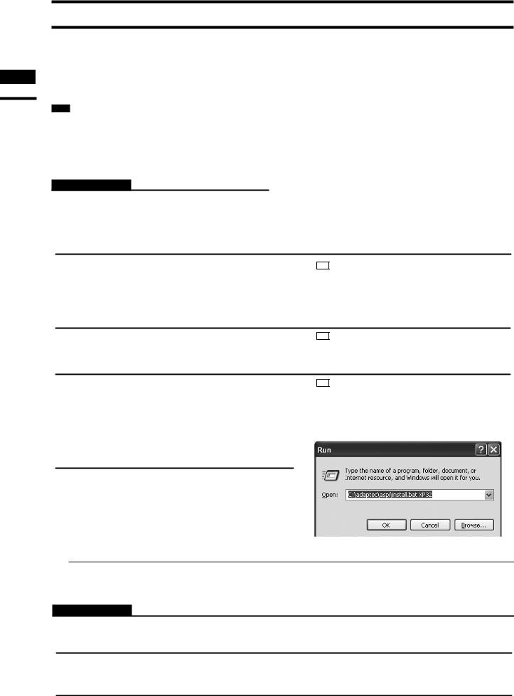
If you use Windows XP, select [Run] from the [Start] menu, and then run the decompressed “INSTALL.BAT” file added “XP32” parameter as following dialog. The install program starts to install.
ν About installation of U2SCX
It is necessary to install Polygon Editing Tool on the computer before installing the driver software of the USB2.0-UltraSCSI converter.
Operating Procedure
1 Start Windows and insert the software CD-ROM into the CD-ROM drive.
2 From Explorer, open the “U2SCX for Vista” (when using Windows Vista) or “U2SCX for Win7” (when using Windows 7 ) directory in the CD-ROM.
3 Proceed to install the driver as described on “Installation of Emulation Driver” in U2SCX_ InstallGuide.
10

4) Installing Polygon Editing Tool on the computer
When installing the software, make sure to install it correctly according to the following procedure.
Memo
It is necessary to connect the protect key to the computer correctly before installing the software.
If the protect key has not yet been connected, connect the protect key to the computer according to the procedure on
page 9.
Operating Procedure
1 Start Windows and insert the software CD-ROM into the CD-ROM drive.
2 From Explorer, execute the “setup.exe”
Below are display examples when Windows Vista is used.
file stored in the CD-ROM.
The setup program will start.
3 Click the [NEXT] button.
A dialog asking whether you agree with the program agreement will appear.
Note
Read it thoroughly and select whether you agree or not.
If you agree, proceed to step 4.
If you do not agree, the software cannot be installed.
Click the [Cancel] button to cancel installation.
Chapter 1
Preparations
4 Select [ I accept the terms in the license agreement. ] and click the [NEXT] button.
Memo If you want to install the software in another directory, click the [Change...] button and select the desired directory. If you do not specify another directory, the software will be installed in “C:\Program Files (x86)\KONICA MINOLTA” in case of a 64-bit OS or “C:\Program Files\ KONICA MINOLTA” in case of a 32-bit OS.
11
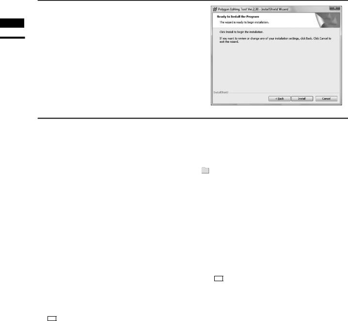
5 Click the [NEXT] button and click the [Install] button.
Chapter 1
Preparations
6 |
Follow the instructions displayed on the |
|
|
screen to complete installation. |
|
|
The Polygon Editing Tool will be installed. |
|
|
When installation is completed successfully, |
|
|
the following files will be created in the direc- |
|
|
tory where the software has been installed. |
KONICA MINOLTA |
 Polygon Editing Tool Ver. .
 Bin
Bin
 PET.exe
•
•
•
 Plugin
 AddTexture.dll
Memo
The files that will be created will change according to the selected installation type.
Memo
When the application software runs for the first time, the “..KONICA MINOLTA\Polygon Editing Tool Ver.*.** \Model” folder will be created in My Documents.
12
5) Connecting the VIVID digitizer to the computer
When the VIVID digitizer will be controlled from Polygon Editing Tool, connect the VIVID digitizer to the computer first, and then start up Polygon Editing Tool.
The first time the VIVID digitizer is connected to the computer, it is necessary for the computer to recognize the VIVID digitizer as an external device.
Perform operations according to the following procedure.
ν Connecting the VIVID digitizer to the computer
In order for the protect key to be recognized by the corresponding driver software, it is necessary to install the driver software on the computer before connecting the protect key to the computer.
Operating Procedure
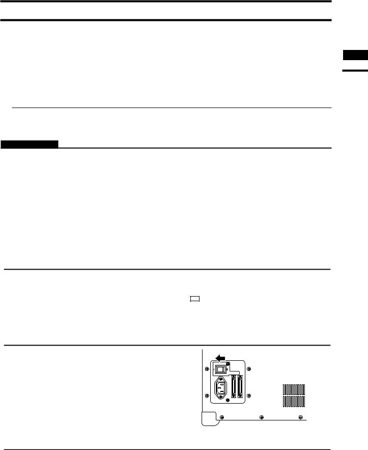
1 Turn the POWER switch of the computer OFF.
2 Connectputer. the VIVID digitizer to the com-
Memo
3 Set the POWER switch of the VIVID digitizer to ON (set switch to “I” mark).
Initializing of the digitizer will start.
4 After MENU appears in the finder of the digitizer, switch on the computer to start the Windows operating system.
Note
The POWER switch of the digitizer should be set to ON first before switching on the computer.
For details on how to connect the VIVID digitizer to the computer, refer to the instruction manual of each model of the VIVID digitizer.
0/7%2
!# ). 3#3)
Chapter 1
Preparations
13
Chapter 1
Preparations
ν Recognition of the VIVID digitizer by the computer
The first time the VIVID digitizer is connected to the computer, cause the computer to recognize the VIVID digitizer as an external device by following the procedure below.
Note
It is not necessary to install the device driver of the VIVID digitizer on the computer; however, Polygon Editing Tool cannot control the digitizer until recognition has been completed.
Operating Procedure
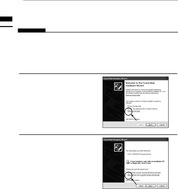
1 After connecting the digitizer to the computer, switch on the computer. The digitizer will be recognized by the computer as a new external device, and then the Hardware Wizard will start.
2 A dialog confirming whether or not to connect to Windows Update will appear first. Check the “No, not this time” checkbox and then click “Next”.
3 When a dialog for confirming the driver installation method appears, check the “Install from a list or specific location (Advanced)” checkbox and then click “Next”.
14
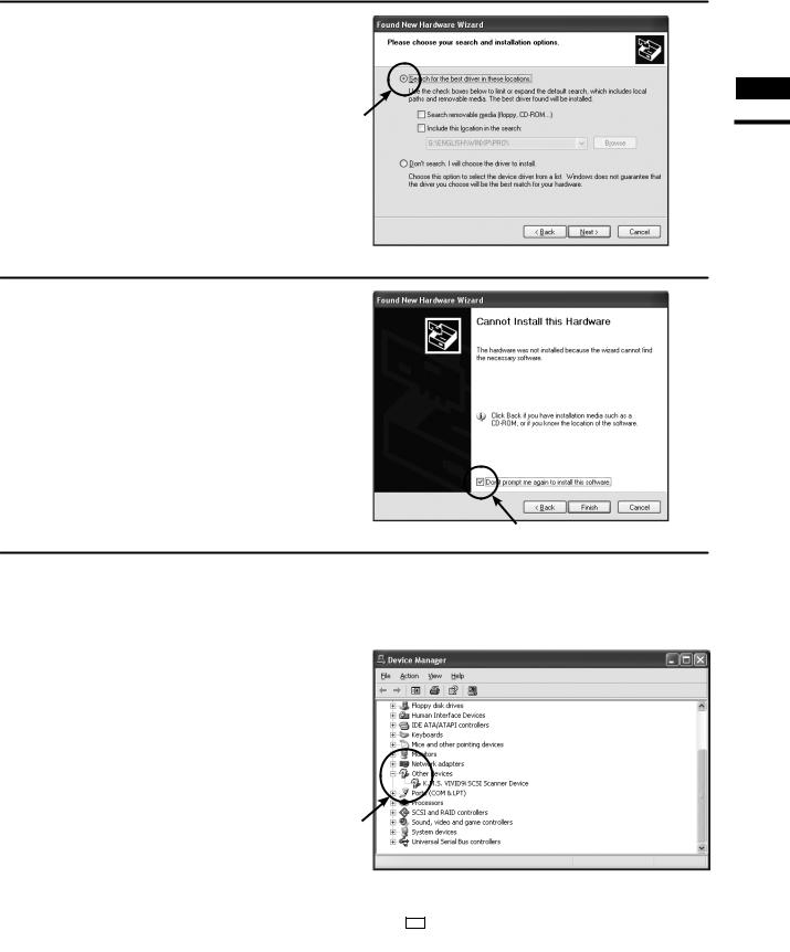
4 When a dialog for specifying the desired driver search method appears, check the “Search for the best driver in these locations.” radio button, clear any other checkbox for specifying the location, and then click “Next”.
5 If a dialog with the message “Cannot Install this Hardware” appears, check the “Don’t prompt me again to install this software.” checkbox and then click “Finish”.
6 Start the device manager to confirm whether or not the VIVID digitizer has been properly recognized by the computer.
Right-click the “My Computer” icon and select “Properties” in the popup menu. When the “System” dialog appears, click “Device Manager” in the “Hardware” tab.
Alternately, open the “Control Panel” from the “Start” menu, double-click the “System” icon to display the “System Properties” dialog, and then click “Device Manager” in the “Hardware” tab.
If the name showing the VIVID digitizer such as “VIVID XXX Scanner Device” appears in the “Other devices” section, recognition of the digitizer has been completed.
Chapter 1
Preparations
Memo
 marks may be displayed on the device icon. This is not a problem.
15
Regarding the software
Chapter 1
Regarding the software
1) Starting and Quitting the Software
ν Starting the Software
Operating Procedure
1 From the [Start] menu, select [Program] –[KONICA MINOLTA], and then click [Polygon Editing Tool Ver. . ].
The Polygon Editing Tool will start.
•If a scene file with the name “startup.scn” currently exists in the directory named “Polygon Editing Tool Ver. . ”
Model”, the program will automatically load this file as it starts up.
Note
When Windows Vista is used and the user account control is available, the [User Account Control] dialog box will appear. Click the [Continue] button.
When Windows 7 is used and UAC (User Account Control) is set to other than “Never notify”, the [User Account Control] dialog box will appear. Click the [Yes] button.
ν Quitting the Software
Operating Procedure
1 Click [Exit] on the [File] menu.
The software will be exited.
16
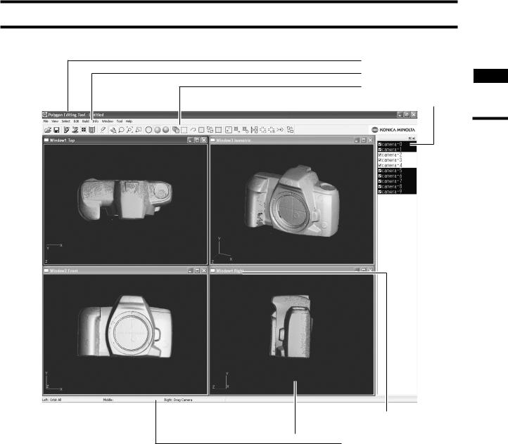
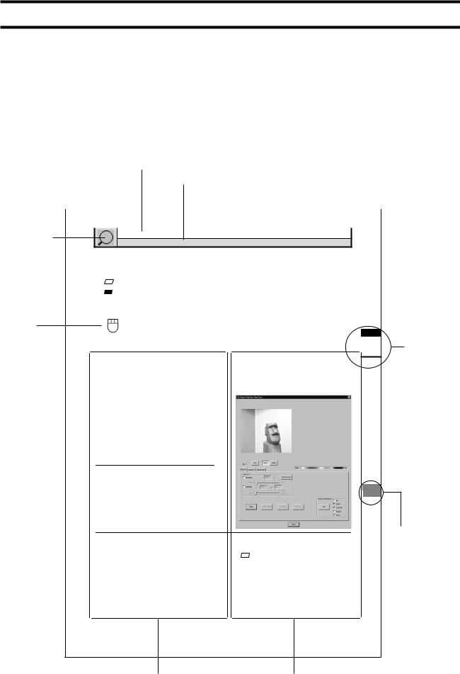
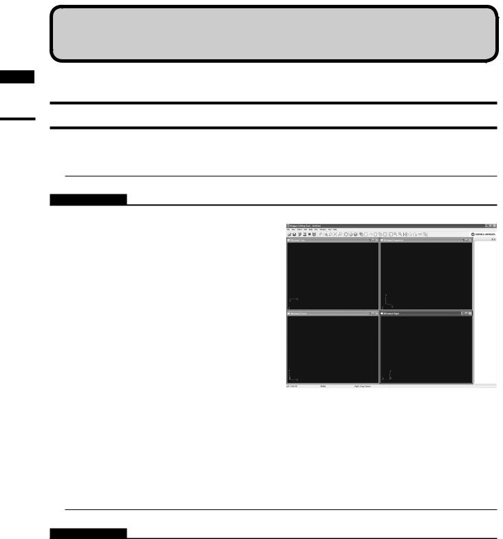
2) Main Window
1. Title bar
2. Menu bar
3. Tool bar 1
Chapter
4. Element list
Regarding the software
5. Window tile  6. Element view window
7. Status bar
1. Title bar Displays the file name of the currently displayed image data. 2. Menu bar Used to select various functions of this software.
3. Tool bar Displays the icons of the frequently used commands. Clicking an icon will execute the corresponding command.
4. Element list Displays the names of all the elements currently opened by this software. Highlighted elements mean that they have been selected by an operation (e.g. by a menu). To select/unselect an element, just click its name.
If you place a checkmark next to an element name, the element will appear in the Element view window. To toggle the display of all selected elements on or off, press the space bar or the [Ctrl] key.
5. Window title Indicates the orientation of the image shown in the window. It is possible to open two or more windows having the same orientation. In the Isometoric or Perspective window, the image can be rotated in different directions using the [Orbit], [Camera Settings] commands of the [View] menu.
6. Element view window Displays the elements whose corresponding checkboxes are checked (i.e. a check mark is displayed).
7. Status bar Displays the function of each button of the mouse according to the currently selectedcommand. (The functions vary with the currently selected command.)
17
Chapter 1
Regarding the software
18
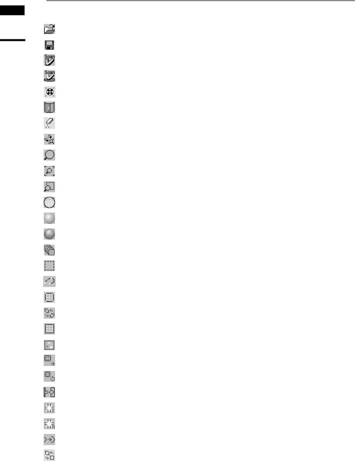
ν Toolbar Icons
Icon |
Command |
Description |
Reference Page |
|
|
|
|
|
File – Open |
Open an element file or scene file. |
24 |
|
|
|
|
|
File – Save – Elements |
Saves element data. |
26 |
|
|
|
|
|
File – Import – Digitizer – One Scan |
Reads in the data from a 1-shot scan by the digitizer. |
33, 50, 74, |
|
103, 118 |
||
|
|
|
|
|
File – Import – Digitizer – Step Scan |
Reads in the data from a step-shot scan by the digi- |
41, 58, 79, |
|
tizer. |
106, 121 |
|
|
|
||
|
File – Import – Digitizer – PSC-1 |
Performing Precision Registration of Scan Data |
136 |
|
for VIVID 9i only; Additional license is required. |
||
|
|
|
|
|
File – Import – Digitizer – Easy Align |
Aligns multiple scans taken by the digitizer. |
126 |
|
|
|
|
|
Edit – Delete – Points |
Deletes a point(s) selected for the currently displayed |
170 |
|
element. |
||
|
|
|
|
|
View – Orbit |
Rotating / moving the camera position |
148 |
|
|
|
|
|
View – Zoom |
Enlarges/reduces the window. |
149 |
|
|
|
|
|
View – Full Frame All |
Fully frames the element in the window. |
150 |
|
|
|
|
|
View – Area Zoom |
Enlarges/reduces the selected area. |
152 |
|
|
|
|
|
Wireframe (Window – Property) |
Displays the wireframe. |
230 |
|
|
|
|
|
Shading (Window – Property) |
Displays the image in shading mode. |
230 |
|
|
|
|
|
Texture (Window – Property) |
Texture-maps the image. |
230 |
|
|
|
|
|
Select – Select Front |
Selects a group of polygon points that are at the front |
166 |
|
and visible. |
||
|
|
|
|
|
Select – Rectangle |
Selecting points within the specified rectangle area. |
159 |
|
|
|
|
|
Select – Bezier |
Selecting points within the specified Bezier curve. |
160 |
|
|
|
|
|
Select – Unselect by Element |
Unselects all the points inside the element. |
166 |
|
|
|
|
|
Select – Toggle Points |
Reverses the selection state of the points. |
165 |
|
|
|
|
|
Select – Boundary – Elements |
Select the points on the boundary of the element. |
162 |
|
|
|
|
|
Build – Registration – Initial – Manual |
Performs initial registration of the specified corre- |
182 |
|
sponding points of elements. |
||
|
|
|
|
|
Build – Move – Elements |
Moves the currently selected elements. |
189 |
|
|
|
|
|
Build – Rotate – Elements |
Rotates the elements. |
198 |
|
|
|
|
|
Build – Merge |
Merges elements to form one element. |
200 |
|
|
|
|
|
Build – Fill Holes – Auto |
Fills holes in the element automatically. |
202 |
|
|
|
|
|
Build – Fill Holes – Manual |
Creates polygon data for the specified points to fill |
201 |
|
holes in the element. |
||
|
|
|
|
|
Build – Smooth – Points |
Smoothens the boundary of the specified points. |
205 |
|
|
|
|
|
Show Vertex/Hide Vertex |
Showing or Hiding Vertices |
244 |
|
|
|
|
Uninstalling
1) Uninstalling the Polygon Editing Tool
To uninstall the software, use the standard uninstall program of Windows.
Remarks
The software will be deleted one folder at a time. If you have a file(s) you want to keep, copy it to another folder before starting uninstallation.
Operating Procedure
1 From the [Start] menu, select [Setting] and then click [Control Panel].
The [Control Panel] window will appear.
2 Double-click the “Add/Remove” icon, select “Polygon Editing Tool” from the list that appears, and then click the [Add/Remove] button.
The uninstall program will start.
3 Follow the instructions displayed on the screen to complete uninstallation.
Chapter 1
Uninstalling
19

Chapter 1
Uninstalling
2) Uninstalling the Protect Key Driver
To uninstall the protect key driver, use the standard uninstall program of Windows.
Memo
Before uninstalling the protect key driver, make sure that the protect key is removed from the computer.
Operating Procedure
1 Remove the protect key from the computer’s USB port.
2 From the [Start] menu, select [Setting] and then click [Control Panel].
The [Control Panel] window will appear.
3 Double-click the “Add/Remove” icon, select “HASP Device Driver” from the list that appears, and then click the [Change/Remove] button.
The uninstall program will start.
4 Follow the instructions displayed on the screen to complete uninstallation.
The protect key driver will be uninstalled.
Memo
After the protect key driver has been uninstalled, restart the computer.
20

Chapter 2
Command Reference
Chapter 2 explains the functions of Polygon Editing Tool, using as keywords the commands that can be selected from the menus of the main window and/or icons of the toolbar.
In addition, the scanning procedure for storing 3-dimensional data by controlling the digitizer from Polygon Editing Tool is also explained.
Chapter 1
Preparations
Regarding the software
Uninstalling
Chapter 2
File
Menu
View
Menu
Select
Menu
Edit
Menu
Build
Menu
Info
Menu
Window
Menu
Tool
Menu
Pop-up Menus
in Element View
Window
Pop-up Menus
in Element List
Pop-up Menus
in Image Window
Chapter
Error
Messages
Explanation of
TechnicalTerms
9i |
910 |
900 |
700 |
300 |
21
22

File Menu
New…………………………………………………………………………………………24 Open… ……………………………………………………………………………………24 Save – Elements……………………………………………………………………………26 Save – Scene… ……………………………………………………………………………27 Save as – Elements…………………………………………………………………………28 Save as – Scene… …………………………………………………………………………29 Import – Elements… ………………………………………………………………………30 Import – Digitizer – One Scan
•When VIVID 9i is Selected … ……………………………………………………33
•When VIVID 910 is Selected……………………………………………………50
•When VIVID 900/910 is Selected…………………………………………………74
•When VIVID 700 is Selected………………………………………………… 103
•When VIVID 300 is Selected………………………………………………… 118
Import – Digitizer – Step Scan
•When VIVID 9i is Selected … ……………………………………………………41
•When VIVID 910 is Selected……………………………………………………58
•When VIVID 900/910 is Selected…………………………………………………79
•When VIVID 700 is Selected………………………………………………… 106
•When VIVID 300 is Selected………………………………………………… 121
Import – Digitizer – PC Card
•When VIVID 910 is Selected……………………………………………………67
•When VIVID 900/910 is Selected…………………………………………………96
•When VIVID 700 is Selected………………………………………………… 111
Import – Digitizer – Easy Align………………………………………………………… 126 Import – Digitizer – Photogrametry System PSC-1… ………………………………… 136
Export – Elements… …………………………………………………………………… 137 Export – Images… ……………………………………………………………………… 140 Remove Elements… …………………………………………………………………… 141 Preferences……………………………………………………………………………… 142 Select Digitizer… ……………………………………………………………………… 144 Exit……………………………………………………………………………………… 145
Chapter 2
File
Menu
9i |
910 |
900 |
700 |
300 |
23
File – New |
[Ctrl] + [N] |
Creating New Scene Data
This command is used to delete the current scene and open a new scene.
Operating Procedure
1 Click [New] on the [File] menu.
The current scene will be deleted and a new blank scene will be generated.
•If modifications have been made to an element after it has been imported or saved, the “Some elements are modified. Do you want to save them?” message dialog box will appear.
Chapter 2
File
Menu
• To save the element data, click the [Yes] button.
• Clicking the [No] button will display the new scene without saving the element data.
Ref. For details of how to save elements, refer to the File
– Save – Elements command (page 26).
9i |
910 |
900 |
700 |
300 |
File – Open |
[Ctrl] + [O] |
Opening Saved Data
This command is used to load an element file or scene file that has been saved using the File – Save – Elements command etc.
Operating Procedure
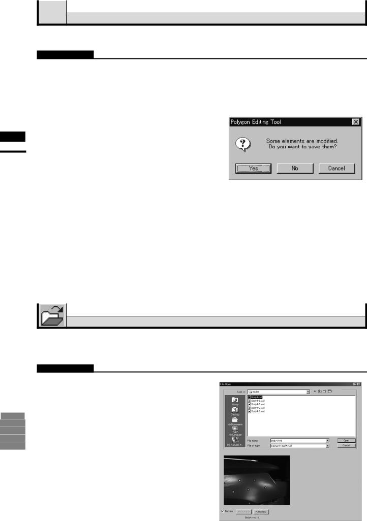
1 Click [Open] on the [File] menu.
The [File-Open] dialog box will appear.
•The dialog box shows a list of files. If all the files cannot be displayed on one page, a scroll bar will be displayed.
24
File – Open
2 Select the file you want to load.
If you select an element file with an attached image and you have also checked the Preview box, the display area will show a preview image.
Note
•It is not possible to select files of different formats.
•In the case of scene files, only one file can be opened.
•It is not possible to open scene files which have been saved using the Utility Software VI-S1.
3 Click the [Open] button.
The data of the selected file(s) will be loaded and displayed in the element view window.
When an element file is loaded:
•The loaded data will be ready to be displayed in all windows. It will be displayed in the active window and the windows for which all the elements are set to be displayed.
•When the data is loaded for the first time after the software is started, it will be fully framed in all the windows including those that are hidden.
•The names of the loaded elements will also appear in the element list, indicating that the elements have been selected (highlighted).
When a scene file is loaded:
•The element list will show the names of the elements contained in the scene, and the view information of each element will be loaded.
The state in effect when a scene file was saved can be restored. However, it cannot always be restored completely, for example, if elements in the file have been set not to be displayed.
•To display files of a certain format only, select the desired format from the [File of type] pull-down menu.
Memo
In the case of element files, it is possible to select two or more files by clicking them while holding down the [Shift] or [Ctrl] key. If two or more files are selected, the preview image can be switched from one file to another
using the [BACKWARD] and [FORWARD] buttons. 2
Chapter
File
Menu
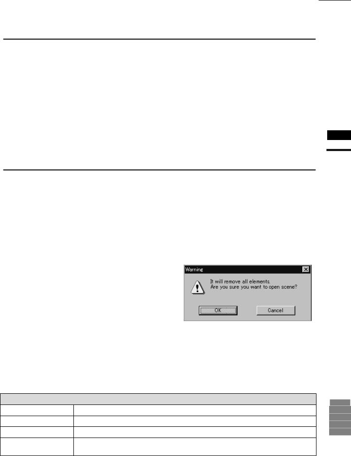
• If an element has already been loaded, the Warning dialog box shown on the right will appear. q Click the [OK] button.
All the elements that have already been loaded will be deleted, and the data of the scene file will be displayed.
Memo
A clock icon will be displayed during loading.
Parameters for [File-Open] Dialog Box |
9i |
||
|
|
||
Look in |
Select the folder containing the file to open. |
910 |
|
File name |
File name selected on the list is displayed. |
900 |
|
700 |
|||
|
|
||
File of type |
Data format of the selected file is displayed. |
300 |
|
Preview |
If you check the Preview box, the [File - Open] dialog box will display preview images of those |
|
|
|
element files that have attached images. |
|
|
25
Chapter 2
File
Menu
File – Save – Elements |
[Ctrl] + [S] |
Saving Element Data
This command is used to save the data selected in the element list. The data will be saved under the current element file name.
Operating Procedure
1 From the element list, select the element(s) to be saved.
2 From the [File] menu, select [Save] and then click [Elements].
Memo
It is possible to select two or more elements by clicking them while holding down the [Shift] or [Ctrl] key.
The selected element data will be saved under the current file name.
•If the selected elements are newly created elements or those that are loaded in another file format, the same dialog box as the one that appears when the File – Save as – Elements command is selected will appear, displaying the element
names in the order they are selected.
q If you want to change the file name, change it and click the [Save] button.
•The first element will be saved, and a dialog box for the next element will appear.
•If you click the [Cancel] button, the next element and subsequent elements will not be saved.
Ref. For details of the File – Save as – Elements command, refer to page 28.
9i |
910 |
900 |
700 |
300 |
26

File – Save – Scene
Saving Scene Data
This command is used to save the current scene data under the current scene file name.
Operating Procedure
1 From the [File] menu, select [Save] and then click [Scene].
The elements comprising the scene and its view information will be saved under the current scene file name.
•If the scene is one that has been newly created, the same dialog box as the one that appears when the File – Save as – Scene command is selected
will appear.
q Enter the desired file name, and click the [Save] button.
The scene will be saved.
Ref. For details of the File – Save as – Scene command, refer to page 29.
Memo
If no elements are present, only the view information will be saved.
Chapter 2
File
Menu
9i |
910 |
900 |
700 |
300 |
27
Chapter 2
File
Menu
File – Save as – Elements
Saving Element Data under a Different Name
This command is used to save the data selected in the element list under a different file name.
Operating Procedure
1 |
From the element list, select the |
Memo |
|
element to be saved. |
It is possible to select two or more elements by clicking |
|
|
|
|
|
them while holding down the [Shift] or [Ctrl] key. |
2 |
From the [File] menu, select [Save as] |
|
|
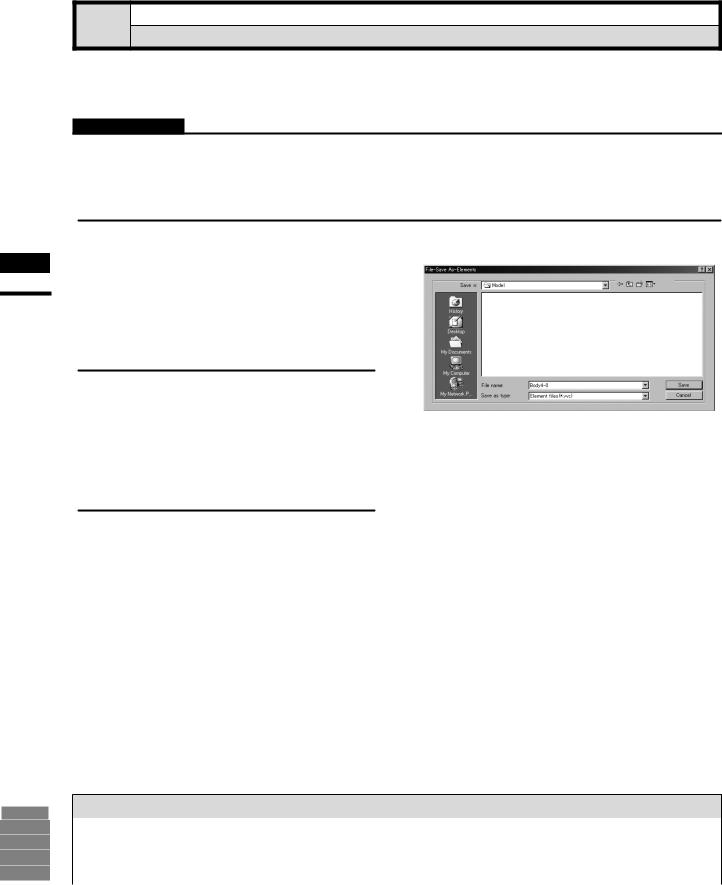
and then click [Elements]. |
|
The [File-Save as-Elements] dialog box will appear.
•If two or more elements have been selected, their names will be displayed in the order they are displayed in the element list.
3 If you want to change the file name, enter a new file name.
Note
The file name must consist of alphanumeric characters only.
Changing the file name will not cause the element names to change.
4 Click the [Save] button.
The first element will be saved, and a dialog box for the next element will appear.
•When all the elements are saved, the dialog box will close.
•If you click the [Cancel] button, the next element and subsequent elements will not be saved.
Memo
By selecting “Element files Ver.1.x” from the [Save as type] pull-down menu, the elements can be saved under the format of the Utility Software VI-S1.
Note
If the elements are saved under the format of the Utility Software VI-S1, data attached to the images may be lost.
9i |
910 |
900 |
700 |
300 |
Parameters for [File-Save As-Elements] Dialog Box
Save in |
Select the folder for saving file. |
|
|
File name |
Input the name of file to save. |
|
|
Save as type |
Select format for saving file. |
|
|
28
Loading...