


1156SBT000AA
EP5000/EP4000
TROUBLESHOOTING

1139SBT0100A
1 INTRODUCTION
1139SBT0101A
1-1. General Precautions
1.When servicing the copier with its covers removed, use utmost care to prevent your hands, clothing, and tools from being caught in revolving parts including the chains and gears. When servicing the copier with the Lower Rear Cover removed, be sure to install the jig.
2.Before attempting to replace parts and unplugging connectors, make sure that the power cord of the copier has been unplugged from the wall outlet.
3.Never create a closed circuit across connector pins except those specified in the text and on the printed circuit.
4.When creating a closed circuit and measuring a voltage across connector pins specified in the text, be sure to use the green wire (GND).
5.When the user is using a word processor or personal computer from the wall outlet of the same line, take necessary steps to prevent the circuit breaker from opening due to overloads.
6.Keep all disassembled parts in good order and keep tools under control so that none will be lost or damaged.
1139SBT0102A
1-2. How to Use This Book
1.If a component on a PWB or any other functional unit including a motor is defective, the text only instructs you to replace the whole PWB or functional unit and does not give troubleshooting procedures applicable within the defective unit.
2.All troubleshooting procedures contained herein assume that there are no breaks in the harnesses and cords and all connectors are plugged into the right positions.
3.For the removal procedures of covers and parts, see DIS/REASSEMBLY, ADJUSTMENT.
4.The troubleshooting procedures are given in the order of greater frequency of trouble or order of operation.
5.The procedures preclude possible malfunctions due to noise and other external causes.
1139SBT0103A
1-3. Reading the Text
1.The paper transport failure troubleshooting procedures are given according to the symptom. First identify the location where the paper is present and start the procedure for that particular location. For malfunction troubleshooting, start with step 1 and onward.
2.Make checks in numerical order of steps and, if an item is checked okay, go to the next step.
Pattern 1
Step |
Check Item |
Result |
Action |
|
1 |
Is...? |
YES |
Do this. |
|
|
|
|
|
|
2 |
|
↑ |
|
|
|
Go to step 2 if you answered NO. |
|
||
|
|
|||
Pattern 2
Step Check Item |
Result |
Action |
|
1 |
Is...? |
YES |
Do this. |
|
NO |
Check that. |
|
|
|
||
2 |
↑ |
|
Go to step 2 if it checks okay. |
||
|
T-1

1151SBT0200A
2 I/O PORT CHECK
1156SBT0201A
2-1. Controlled Parts Check Procedure
To allow the Tech. Rep. to easily and safely determine whether a particular controlled part is fully operational, this copier provides the following provision: checking the data of the I/O port of the board IC with the copier in the standby state (including a misfeed, malfunction, and closure failure condition) allows the Tech. Rep. to determine whether a signal is properly input to, and output from, a controlled part.
<Procedure>
1)On the circuit diagram accompanying the text, locate the I/O port of the controlled part which is probably defective when a misfeed or malfunction occurs.
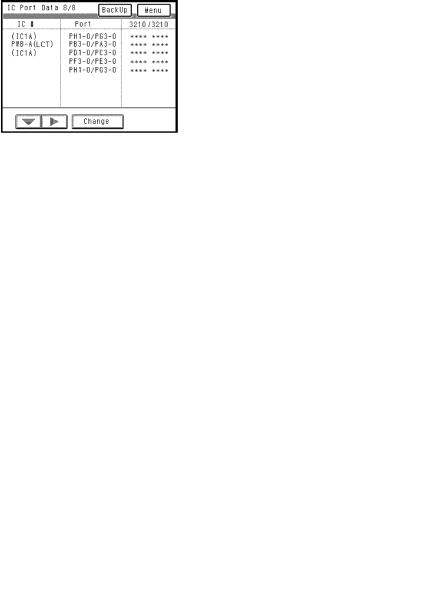
2)Select the “IC Port Data Check” function of “I/O Check” in the Tech. Rep. mode and access the screen which contains the port identified in step 1 above. (See SWITCHES ON PWBs/TECH. REP. MODE.)
3)Change or check the input or output port data to determine whether the controlled part is operational and signals are properly input and output.
4)If the controlled part does not operate properly after changing the output port data, select “Controller Board Check” of “I/O Check” in the Tech. Rep. mode and determine whether the board is responsible for that malfunction or not.
Note: Only the output ports given on pages T-37 and 38 may be checked by “Controller Board Check” of “I/O Check” in the Tech. Rep. mode.
T-2

<Controlled Part Check Procedure by Changing Input Port Data>
Example: When a paper misfeed occurs in the paper take-up section of the copier, 1st Drawer Paper Take-Up Sensor PC56 is considered to be responsible for it.
<Procedure>
1)Remove the sheet of paper misfed and reset the misfeed.
2)From the I/O port check list, it is found that the H/L input signal to PC56 is supplied from PWB-A (IC3A) APB3.
3)Select “IC Port Check” from the I/O Check function in the Tech. Rep. mode and access the screen which includes the input ports of PWB-A (IC3A) APB3.
4)Check that the input port data of PWB-A (IC3A) APB3 on the screen is “H” (sensor being unblocked).
5)Move the PC56 actuator to block the sensor.
6)Return to the “I/O Check” basic screen once, select “IC Port Check” again, choose the screen which includes the APB3 input port data, and make sure that the data has changed from “H” to “L”.
L: PC56 is operational. |
H: PC56 is faulty. |
|||||||||||||||||||||||||
|
|
|
|
|
|
|
|
|
|
|
|
|
|
|
|
|
|
|
|
|
|
|
|
|
|
|
T-3

<Controlled Part Check Procedure by Changing Output Port Data>
Example: When a manual paper misfeed occurs, Manual Feed Paper Take-Up Clutch CL3 is considered to be responsible for it.
<Procedure>
1)Remove the sheet of paper misfed and reset the misfeed.
2)From the I/O port check list, it is found that the ON/OFF output signal of CL3 is supplied from PWB-A (IC5A) BPA1.
3)Select “IC Port Check” from the I/O Check function in the Tech. Rep. mode and access the screen which includes the output ports of PWB-A (IC5A) BPA1.
4)Check that the output port data of PWB-A (IC5A) BPA1 on the screen is “1” (CL3 is deenergized).
5)Touch the “CHANGE” key on the screen to change the data from “1” to “0”, causing CL3 to be energized for approx. 5 seconds. This allows you to determine whether the Clutch is “operational or faulty” by checking for the Clutch sound.
Operational: Sound produced. |
Faulty: No sound produced. |
6)If CL3 was not energized, make the “Controller Board Check” in the same mode (for some electrical parts only).
7)If the “ON” signal of CL51 is not output from PWB-A, the corresponding malfunction code is displayed.
*For CL3, “C0337” is displayed.
T-4
1156SBT0202A
2-2. I/O Port Check List
<Port Check Screens>
D The following screens are displayed in the standby mode but may not always be as shown below because some port data are undefined. (Copier+PF-205)
1156T016CA |
1156T020CA |
|
1156T017CA |
1156T021CA |
1156T018CA |
1156T022CA |
1156T019CA |
1156T023CA |
T-5
<I/O Port Check List>
Copier |
*The shaded areas of the following table indicate that the output check cannot be made by |
||||||||
|
touching the Change key. |
|
|
|
|
|
|
|
|
|
|
|
|
|
|
|
|
|
|
|
|
Dis- |
|
|
|
Operation Char- |
|
||
Sym- |
|
IC |
Port |
|
acteristics/Panel |
CN/PJ |
|||
Parts/Signal Name |
play |
I/O |
|||||||
bol |
No. |
No. |
Display |
No. |
|||||
|
Page |
|
|||||||
|
|
|
|
|
H or 1 |
L or 0 |
|
||
|
|
|
|
|
|
|
|||
|
|
|
|
|
|
|
|
|
|
M1 |
Main Drive Motor/REM |
2/8 |
IC4A |
BPA2 |
f |
OFF |
ON |
PJ18A-9 |
|
|
|
|
|
|
|
|
|
|
|
↑ |
Main Drive Motor/lock |
2/8 |
IC4A |
BPB1 |
|
When |
When |
PJ18A-10 |
|
signal |
locked |
turned |
|||||||
|
|
|
|
|
|
||||
|
|
|
|
|
|
|
|
|
|
M2 |
Scanner Motor/SCAN |
3/8 |
IC4A |
APC0 |
f |
Stop |
Scan |
PJ8A-5 |
|
cycle |
|||||||||
|
|
|
|
|
|
|
|
||
|
|
|
|
|
|
|
|
|
|
M3 |
Ventilation Fan Motor/ |
3/8 |
IC4A |
BPC1 |
f |
OFF |
ON |
PJ34A-1 |
|
REM |
|||||||||
|
|
|
|
|
|
|
|
||
|
|
|
|
|
|
|
|
|
|
↑ |
Ventilation Fan Motor/ |
2/8 |
IC4A |
BPB6 |
|
When |
When |
PJ34A-3 |
|
lock signal |
locked |
turned |
|||||||
|
|
|
|
|
|
||||
|
|
|
|
|
|
|
|
|
|
|
Suction Fan Motor/se- |
|
|
|
|
Turned |
Turned |
|
|
M4 |
3/8 |
IC4A |
BPC2 |
f |
at high |
at low |
PJ15A-4 |
||
lect signal |
|||||||||
|
|
|
|
|
speed |
speed |
|
||
|
|
|
|
|
|
|
|||
|
|
|
|
|
|
|
|
|
|
↑ |
Suction Fan Motor/lock |
3/8 |
IC4A |
BPC7 |
|
When |
When |
PJ15A-3 |
|
signal |
locked |
turned |
|||||||
|
|
|
|
|
|
||||
|
|
|
|
|
|
|
|
|
|
M5 |
Original Glass Cooling |
3/8 |
IC4A |
BPC0 |
f |
OFF |
ON |
PJ15A-5 |
|
Fan Motor/REM |
|||||||||
|
|
|
|
|
|
|
|
||
|
|
|
|
|
|
|
|
|
|
↑ |
Original Glass Cooling |
2/8 |
IC4A |
BPB5 |
|
When |
When |
PJ15A-7 |
|
Fan Motor/lock signal |
locked |
turned |
|||||||
|
|
|
|
|
|
||||
|
|
|
|
|
|
|
|
|
|
M8 |
Main Hopper Toner Re- |
3/8 |
IC4A |
BPC3 |
f |
OFF |
ON |
PJ11A-4A |
|
plenishing Motor/REM |
|||||||||
|
|
|
|
|
|
|
|
||
M9 |
Sub Hopper Toner Re- |
3/8 |
IC5A |
APA2 |
f |
OFF |
ON |
PJ11A-2A |
|
plenishing Motor/REM |
|||||||||
|
|
|
|
|
|
|
|
||
|
|
|
|
|
|
|
|
|
|
|
1st Drawer Paper Take- |
|
|
|
|
Turn in- |
Turn |
|
|
M11 |
3/8 |
IC5A |
APA0 |
f |
per- |
PJ18A-1 |
|||
Up Motor |
hibited |
||||||||
|
|
|
|
|
mitted |
|
|||
|
|
|
|
|
|
|
|
||
|
|
|
|
|
|
|
|
|
|
|
2nd Drawer Paper Take- |
|
|
|
|
Turn in- |
Turn |
|
|
M12 |
3/8 |
IC5A |
APA1 |
f |
per- |
PJ18A-2 |
|||
Up Motor |
hibited |
||||||||
|
|
|
|
|
mitted |
|
|||
|
|
|
|
|
|
|
|
||
|
|
|
|
|
|
|
|
|
|
M13 |
1st Drawer Paper Lift-Up |
3/8 |
IC5A |
APA4 |
f |
OFF |
ON (up) |
PJ18A-5 |
|
Motor (UP) |
|||||||||
|
|
|
|
|
|
|
|
||
↑ |
1st Drawer Paper Lift-Up |
3/8 |
IC5A |
APA5 |
f |
OFF |
ON |
PJ18A-6 |
|
Motor (DOWN) |
(down) |
||||||||
|
|
|
|
|
|
|
|||
M14 |
2nd Drawer Paper |
3/8 |
IC5A |
APA6 |
f |
OFF |
ON (up) |
PJ8A-7 |
|
Lift-Up Motor (UP) |
|||||||||
|
|
|
|
|
|
|
|
||
↑ |
2nd Drawer Paper |
3/8 |
IC5A |
APA7 |
f |
OFF |
ON |
PJ18A-8 |
|
Lift-Up Motor (DOWN) |
(down) |
||||||||
|
|
|
|
|
|
|
|||
M15 |
Fusing Section Cooling |
3/8 |
IC4A |
APC2 |
f |
OFF |
ON |
PJ10A-1 |
|
Fan Motor/REM |
|||||||||
|
|
|
|
|
|
|
|
||
|
|
|
|
|
|
|
|
|
|
T-6
|
|
Dis- |
|
|
|
Operation Char- |
|
||
|
|
IC |
Port |
|
acteristics/Panel |
CN/PJ |
|||
Symbol |
Parts/Signal Name |
play |
I/O |
||||||
No. |
No. |
Display |
No. |
||||||
|
|
Page |
|
||||||
|
|
|
|
|
H or 1 |
L or 0 |
|
||
|
|
|
|
|
|
|
|||
|
|
|
|
|
|
|
|
|
|
|
Fusing Section Cool- |
|
|
|
|
When |
When |
|
|
↑ |
ing Fan Motor/lock |
3/8 |
IC4A |
APB6 |
|
PJ10A-3 |
|||
locked |
turned |
||||||||
|
signal |
|
|
|
|
|
|||
|
|
|
|
|
|
|
|
||
|
|
|
|
|
|
|
|
|
|
SL1 |
Separator Solenoid |
2/8 |
IC4A |
BPA0 |
f |
OFF |
ON |
PJ11A-6A |
|
|
|
|
|
|
|
|
|
|
|
SL5 |
Exit/Duplex Switching |
2/8 |
IC4A |
BPA5 |
f |
OFF |
ON |
PJ14A-6 |
|
Solenoid |
|||||||||
|
|
|
|
|
|
|
|
||
|
|
|
|
|
|
|
|
|
|
|
Manual Feed Paper |
|
|
|
|
|
ON |
|
|
SL51 |
Take-Up Solenoid |
3/8 |
IC5A |
BPA2 |
f |
OFF |
PJ15A-10 |
||
(up) |
|||||||||
|
(UP) |
|
|
|
|
|
|
||
|
|
|
|
|
|
|
|
||
|
|
|
|
|
|
|
|
|
|
|
Manual Feed Paper |
|
|
|
|
|
ON |
|
|
↑ |
Take-Up Solenoid |
3/8 |
IC5A |
BPA3 |
f |
OFF |
PJ15A-9 |
||
(down) |
|||||||||
|
(DOWN) |
|
|
|
|
|
|
||
|
|
|
|
|
|
|
|
||
|
|
|
|
|
|
|
|
|
|
CL1 |
Paper Transport |
2/8 |
IC4A |
BPA3 |
f |
OFF |
ON |
PJ14A-2 |
|
Clutch |
|||||||||
|
|
|
|
|
|
|
|
||
|
|
|
|
|
|
|
|
|
|
CL2 |
Synchronizing Roller |
2/8 |
IC4A |
BPA4 |
f |
OFF |
ON |
PJ14A-4 |
|
Clutch |
|||||||||
|
|
|
|
|
|
|
|
||
|
|
|
|
|
|
|
|
|
|
CL3 |
Manual Feed Paper |
3/8 |
IC5A |
BPA1 |
f |
OFF |
ON |
PJ15A-12 |
|
Take-Up Clutch |
|||||||||
|
|
|
|
|
|
|
|
||
|
|
|
|
|
|
|
|
|
|
|
Duplex Unit Vertical |
|
|
|
|
Paper |
Paper |
|
|
PC12 |
3/8 |
IC5A |
BPB0 |
|
not |
PJ17A-8 |
|||
Transport Sensor |
present |
||||||||
|
|
|
|
|
present |
|
|||
|
|
|
|
|
|
|
|
||
|
|
|
|
|
|
|
|
|
|
PC35 |
Toner Bottle Home |
3/8 |
IC4A |
BPC5 |
|
Un- |
Blocked |
PJ11A-9 |
|
Position Sensor |
blocked |
||||||||
|
|
|
|
|
|
|
|||
|
|
|
|
|
|
|
|
|
|
|
Manual Feed Paper |
|
|
|
|
Paper |
Paper |
|
|
PC51 |
3/8 |
IC5A |
BPB1 |
|
not |
PJ15A-14 |
|||
Empty Sensor |
present |
||||||||
|
|
|
|
|
present |
|
|||
|
|
|
|
|
|
|
|
||
|
|
|
|
|
|
|
|
|
|
|
Transport Roller Sen- |
|
|
|
|
Paper |
Paper |
|
|
PC54 |
3/8 |
IC5A |
BPB6 |
|
not |
PJ19A-5 |
|||
sor |
present |
||||||||
|
|
|
|
|
present |
|
|||
|
|
|
|
|
|
|
|
||
|
|
|
|
|
|
|
|
|
|
|
Paper Leading Edge |
|
|
|
|
Paper |
Paper |
|
|
PC55 |
3/8 |
IC5A |
BPB5 |
|
not |
PJ19A-2 |
|||
Detecting Sensor |
present |
||||||||
|
|
|
|
|
present |
|
|||
|
|
|
|
|
|
|
|
||
|
|
|
|
|
|
|
|
|
|
|
1st Drawer Paper |
|
|
|
|
Paper |
Paper |
|
|
PC56 |
1/8 |
IC3A |
APB3 |
|
not |
PJ21A-5A |
|||
Take-Up Sensor |
present |
||||||||
|
|
|
|
|
present |
|
|||
|
|
|
|
|
|
|
|
||
|
|
|
|
|
|
|
|
|
|
|
2nd Drawer Paper |
|
|
|
|
Paper |
Paper |
|
|
PC57 |
1/8 |
IC3A |
APB4 |
|
not |
PJ21A-5B |
|||
Take-Up Sensor |
present |
||||||||
|
|
|
|
|
present |
|
|||
|
|
|
|
|
|
|
|
||
|
|
|
|
|
|
|
|
|
|
PC61 |
1st Drawer Set Sen- |
1/8 |
IC3A |
BPA5 |
|
Out of |
In |
PJ22A-2 |
|
sor |
position |
position |
|||||||
|
|
|
|
|
|
||||
|
|
|
|
|
|
|
|
|
|
PC62 |
2nd Drawer Set Sen- |
1/8 |
IC3A |
APB5 |
|
Out of |
In |
PJ22A-6 |
|
sor |
position |
position |
|||||||
|
|
|
|
|
|
||||
|
|
|
|
|
|
|
|
|
|
T-7
|
|
Dis- |
|
|
|
Operation Charac- |
|
|||
Sym- |
|
IC |
Port |
|
teristics/Panel Dis- |
CN/PJ |
||||
Parts/Signal Name |
play |
I/O |
||||||||
bol |
No. |
No. |
play |
|
No. |
|||||
|
Page |
|
|
|||||||
|
|
|
|
|
H or 1 |
L or 0 |
|
|||
|
|
|
|
|
|
|
||||
|
|
|
|
|
|
|
|
|
|
|
|
1st Drawer Vertical |
|
|
|
|
Paper |
Paper |
|
||
PC63 |
1/8 |
IC3A |
APB6 |
|
not |
PJ21A-8A |
||||
Transport Sensor |
present |
|||||||||
|
|
|
|
|
present |
|
||||
|
|
|
|
|
|
|
|
|
||
|
|
|
|
|
|
|
|
|
|
|
|
2nd Drawer Vertical |
|
|
|
|
Paper |
Paper |
|
||
PC64 |
1/8 |
IC3A |
APB7 |
|
not |
PJ21A-8B |
||||
Transport Sensor |
present |
|||||||||
|
|
|
|
|
present |
|
||||
|
|
|
|
|
|
|
|
|
||
|
|
|
|
|
|
|
|
|
|
|
|
1st Drawer Lift-Up |
|
|
|
|
Not at |
At |
up- |
|
|
PC65 |
1/8 |
IC3A |
APB1 |
|
upper |
PJ21A-2A |
||||
Sensor |
per limit |
|||||||||
|
|
|
|
|
limit |
|
||||
|
|
|
|
|
|
|
|
|
||
|
|
|
|
|
|
|
|
|
|
|
|
2nd Drawer Lift-Up |
|
|
|
|
Not at |
At |
up- |
|
|
PC66 |
1/8 |
IC3A |
APB2 |
|
upper |
PJ21A-2B |
||||
Sensor |
per limit |
|||||||||
|
|
|
|
|
limit |
|
||||
|
|
|
|
|
|
|
|
|
||
|
|
|
|
|
|
|
|
|
|
|
PC67 |
1st Drawer Lift-Up |
1/8 |
IC3A |
APC0 |
|
Un- |
Blocked |
PJ23A-2 |
||
Motor Pulse Sensor |
blocked |
|||||||||
|
|
|
|
|
|
|
|
|||
|
|
|
|
|
|
|
|
|
|
|
PC68 |
2nd Drawer Lift-Up |
1/8 |
IC3A |
APC1 |
|
Un- |
Blocked |
PJ23A-5 |
||
Motor Pulse Sensor |
blocked |
|||||||||
|
|
|
|
|
|
|
|
|||
|
|
|
|
|
|
|
|
|
|
|
|
1st Drawer Lower |
|
|
|
|
Not at |
At lower |
|
||
PC69 |
Limit Position Sen- |
1/8 |
IC3A |
BPA2 |
|
lower |
PJ24A-5 |
|||
|
limit |
|||||||||
|
sor |
|
|
|
|
limit |
|
|
||
|
|
|
|
|
|
|
|
|||
|
|
|
|
|
|
|
|
|
|
|
|
2nd Drawer Lower |
|
|
|
|
Not at |
At lower |
|
||
PC70 |
Limit Position Sen- |
1/8 |
IC3A |
BPA3 |
|
lower |
PJ24A-6 |
|||
|
limit |
|||||||||
|
sor |
|
|
|
|
limit |
|
|
||
|
|
|
|
|
|
|
|
|||
|
|
|
|
|
|
|
|
|
||
PC72 |
Paper Size Detect- |
2/8 |
IC3A |
BPB6 |
|
Size not |
Size de- |
PJ25A-2 |
||
ing Sensor 5 |
detected |
tected |
||||||||
|
|
|
|
|
|
|||||
|
|
|
|
|
|
|
|
|
||
PC73 |
Paper Size Detect- |
2/8 |
IC3A |
BPB7 |
|
Size not |
Size de- |
PJ25A-5 |
||
ing Sensor 6 |
detected |
tected |
||||||||
|
|
|
|
|
|
|||||
|
|
|
|
|
|
|
|
|
|
|
PC81 |
Scanner Reference |
2/8 |
IC4A |
APC4 |
|
Not at |
At home |
PJ8A-4 |
||
Position Sensor |
home |
|||||||||
|
|
|
|
|
|
|
|
|||
|
|
|
|
|
|
|
|
|
|
|
|
1st Drawer Paper |
|
|
|
|
Paper |
Paper |
|
||
PC101 |
1/8 |
IC3A |
APC2 |
|
not |
PJ23A-9 |
||||
Empty Sensor |
present |
|||||||||
|
|
|
|
|
present |
|
||||
|
|
|
|
|
|
|
|
|
||
|
|
|
|
|
|
|
|
|
|
|
|
2nd Drawer Paper |
|
|
|
|
Paper |
Paper |
|
||
PC102 |
1/8 |
IC3A |
APC3 |
|
not |
PJ23A-12 |
||||
Empty Sensor |
present |
|||||||||
|
|
|
|
|
present |
|
||||
|
|
|
|
|
|
|
|
|
||
|
|
|
|
|
|
|
|
|
|
|
PC111 |
Original Cover |
2/8 |
IC4A |
APB5 |
|
Raised |
Lowered |
PJ12A-1 |
||
Detecting Sensor |
||||||||||
|
|
|
|
|
|
|
|
|
||
|
|
|
|
|
|
|
|
|
|
|
PC112 |
Toner Hopper Home |
3/8 |
IC5A |
BPB7 |
|
Not at |
At home |
PJ11A-9B |
||
Position Sensor |
home |
|||||||||
|
|
|
|
|
|
|
|
|||
|
|
|
|
|
|
|
|
|
||
CNT1 |
Total Counter/REM |
1/8 |
IC1A |
P55 |
f |
Normally |
When |
PJ13A-6 |
||
counting |
||||||||||
|
|
|
|
|
|
|
|
|||
↑ |
Total Counter/Set |
2/8 |
IC4A |
APB7 |
|
Out of |
In |
posi- |
− |
|
position |
|
tion |
||||||||
|
|
|
|
|
|
|
|
|||
|
|
|
|
|
|
|
|
|
|
|
T-8
|
|
Dis- |
|
|
|
Operation Charac- |
|
||
Sym- |
|
IC |
Port |
|
teristics/Panel Dis- |
CN/PJ |
|||
Parts/Signal Name |
play |
I/O |
|||||||
bol |
No. |
No. |
play |
No. |
|||||
|
Page |
|
|||||||
|
|
|
|
|
H or 1 |
L or 0 |
|
||
|
|
|
|
|
|
|
|||
|
|
|
|
|
|
|
|
|
|
|
|
|
|
|
|
|
When |
|
|
CNT2 |
Plug-In Counter/REM |
1/8 |
IC1A |
P44 |
f |
Normally |
count- |
PJ28A-9 |
|
|
|
|
|
|
|
|
ing |
|
|
↑ |
Plug-In Counter/Set |
3/8 |
IC5A |
BPC3 |
|
Out of |
In |
PJ28A-7 |
|
position |
position |
||||||||
|
|
|
|
|
|
|
|||
|
|
|
|
|
|
|
|
|
|
H1 |
Fusing Heater Lamp |
1/8 |
IC1A |
P57 |
f |
OFF |
ON |
PJ33A-2 |
|
|
|
|
|
|
|
|
|
|
|
H3 |
Paper Dehumidifying |
1/8 |
IC1A |
P45 |
f |
ON |
OFF |
PJ4A-5 |
|
Heater |
|||||||||
|
|
|
|
|
|
|
|
||
|
|
|
|
|
|
|
|
|
|
RY1 |
Main Relay |
1/8 |
IC1A |
P46 |
f |
ON |
OFF |
PJ4A-3 |
|
LA1 |
Exposure Lamp/AVR |
1/8 |
IC1A |
P61 |
f |
OFF |
ON |
PJ8A-13 |
|
REM |
|||||||||
|
|
|
|
|
|
|
|
||
LA2 |
Main Erase Lamp/ |
2/8 |
IC4A |
BPA1 |
f |
OFF |
ON |
PJ12A-3 |
|
REM |
|||||||||
|
|
|
|
|
|
|
|
||
LA2 |
Main Erase Lamp/ |
2/8 |
IC4A |
APC7 |
|
OFF |
ON |
PJ12A-5 |
|
failure detection |
|||||||||
|
|
|
|
|
|
|
|
||
|
|
|
|
|
|
|
|
|
|
S1 |
Power Switch |
1/8 |
IC1A |
P53 |
|
OFF |
ON |
PJ4A-1 |
|
S21 |
Front Door Interlock |
1/8 |
IC1A |
P51 |
|
OFF |
ON |
PJ4A-4 |
|
Switch |
|||||||||
|
|
|
|
|
|
|
|
||
|
|
|
|
|
|
|
|
|
|
S22 |
Right Upper Door |
3/8 |
IC5A |
BPB2 |
|
OFF |
ON |
PJ16A-2 |
|
Interlock Switch |
|||||||||
|
|
|
|
|
|
|
|
||
|
|
|
|
|
|
|
|
|
|
S23 |
Left Upper Door |
3/8 |
IC5A |
BPC6 |
|
OFF |
ON |
PJ16A-4 |
|
Interlock Switch |
|||||||||
|
|
|
|
|
|
|
|
||
|
|
|
|
|
|
|
|
|
|
|
|
|
|
|
|
Paper |
Paper |
|
|
S53 |
Paper Exit Switch |
3/8 |
IC4A |
BPB2 |
|
not |
PJ20A-12 |
||
present |
|||||||||
|
|
|
|
|
|
present |
|
||
|
|
|
|
|
|
|
|
||
|
|
|
|
|
|
|
|
|
|
|
Paper Size Detecting |
|
|
|
|
Size yet |
Size de- |
|
|
S61 |
1/8 |
IC3A |
BPA6 |
|
to be de- |
PJ26A-2 |
|||
Switch 1 |
tected |
||||||||
|
|
|
|
|
tected |
|
|||
|
|
|
|
|
|
|
|
||
|
|
|
|
|
|
|
|
|
|
|
Paper Size Detecting |
|
|
|
|
Size yet |
Size de- |
|
|
S62 |
1/8 |
IC3A |
BPA7 |
|
to be de- |
PJ26A-4 |
|||
Switch 2 |
tected |
||||||||
|
|
|
|
|
tected |
|
|||
|
|
|
|
|
|
|
|
||
|
|
|
|
|
|
|
|
|
|
|
Paper Size Detecting |
|
|
|
|
Size yet |
Size de- |
|
|
S63 |
2/8 |
IC3A |
BPB4 |
|
to be de- |
PJ26A-7 |
|||
Switch 3 |
tected |
||||||||
|
|
|
|
|
tected |
|
|||
|
|
|
|
|
|
|
|
||
|
|
|
|
|
|
|
|
|
|
|
Paper Size Detecting |
|
|
|
|
Size yet |
Size de- |
|
|
S64 |
2/8 |
IC3A |
BPB5 |
|
to be de- |
PJ26A-9 |
|||
Switch 4 |
tected |
||||||||
|
|
|
|
|
tected |
|
|||
|
|
|
|
|
|
|
|
||
|
|
|
|
|
|
|
|
|
|
|
Toner Empty |
|
|
|
|
Toner |
Toner |
|
|
S106 |
3/8 |
IC1A |
BPC6 |
|
still avail- |
PJ11A-8B |
|||
Detecting Switch |
empty |
||||||||
|
|
|
|
|
able |
|
|||
|
|
|
|
|
|
|
|
||
|
|
|
|
|
|
|
|
|
|
T-9
|
|
Dis- |
|
|
|
Operation Charac- |
|
|||
Sym- |
|
IC |
Port |
|
teristics/Panel Dis- |
CN/PJ |
||||
Parts/Signal Name |
play |
I/O |
||||||||
bol |
No. |
No. |
|
play |
No. |
|||||
|
Page |
|
|
|||||||
|
|
|
|
|
H or 1 |
|
L or 0 |
|
||
|
|
|
|
|
|
|
|
|||
|
|
|
|
|
|
|
|
|
|
|
UN5 |
1st Drawer Paper |
1/8 |
IC3A |
BPA0 |
|
OFF |
|
ON |
PJ24A-3 |
|
Descent Key |
|
|||||||||
|
|
|
|
|
|
|
|
|
||
|
|
|
|
|
|
|
|
|
|
|
↑ |
Manual Down |
1/8 |
IC3A |
APC4 |
f |
OFF |
|
ON |
PJ24A-1 |
|
Display 1 |
|
|||||||||
|
|
|
|
|
|
|
|
|
||
|
|
|
|
|
|
|
|
|
|
|
UN6 |
2nd Drawer Paper |
1/8 |
IC3A |
BPA1 |
|
OFF |
|
ON |
PJ24A-4 |
|
Descent Key |
|
|||||||||
|
|
|
|
|
|
|
|
|
||
|
|
|
|
|
|
|
|
|
|
|
↑ |
Manual Down |
1/8 |
IC3A |
APC5 |
f |
OFF |
|
ON |
PJ24A-2 |
|
Display 2 |
|
|||||||||
|
|
|
|
|
|
|
|
|
||
|
|
|
|
|
|
|
|
|
|
|
PWB-G |
AIDC Sensor Board/ |
2/8 |
IC4A |
APA4 |
f |
OFF |
|
ON |
− |
|
AIDC REM |
|
|||||||||
|
|
|
|
|
|
|
|
|
||
|
|
|
|
|
|
|
|
|
|
|
T-10
PF-205
|
|
Dis- |
|
|
|
Operation Char- |
|
||
|
|
IC |
Port |
|
acteristics/Panel |
CN/PJ |
|||
Symbol |
Parts/Signal Name |
play |
I/O |
||||||
No. |
No. |
Display |
No. |
||||||
|
|
Page |
|
||||||
|
|
|
|
|
H or 1 |
L or 0 |
|
||
|
|
|
|
|
|
|
|||
|
|
|
|
|
|
|
|
|
|
|
Vertical Transport |
|
|
|
|
Turn in- |
Turn |
PJ12A-1~ |
|
M21 |
4/8 |
IC1A |
PB3 |
f |
per- |
||||
Drive Motor |
hibited |
4 |
|||||||
|
|
|
|
|
mitted |
||||
|
|
|
|
|
|
|
|
||
|
|
|
|
|
|
|
|
|
|
|
3rd Drawer Paper |
|
|
|
|
Turn in- |
Turn |
PJ11A-1~ |
|
M22 |
4/8 |
IC1A |
PB1 |
f |
per- |
||||
Take-Up Motor |
hibited |
4 |
|||||||
|
|
|
|
|
mitted |
||||
|
|
|
|
|
|
|
|
||
|
|
|
|
|
|
|
|
|
|
|
4th Drawer Paper |
|
|
|
|
Turn in- |
Turn |
PJ10A-1~ |
|
M23 |
4/8 |
IC1A |
PB0 |
f |
per- |
||||
Take-Up Motor |
hibited |
4 |
|||||||
|
|
|
|
|
mitted |
||||
|
|
|
|
|
|
|
|
||
|
|
|
|
|
|
|
|
|
|
M24 |
3rd Drawer Paper |
4/8 |
IC1A |
PA0 |
f |
− |
ON (up) |
PJ9A-8B |
|
Lift-Up Motor |
|||||||||
|
|
|
|
|
|
|
|
||
↑ |
3rd Drawer Paper |
4/8 |
IC1A |
PA1 |
f |
OFF |
ON |
PJ9A-7B |
|
Lift-Up Motor |
(down) |
||||||||
|
|
|
|
|
|
|
|||
M25 |
4th Drawer Paper Lift- |
4/8 |
IC1A |
PA2 |
f |
− |
ON (up) |
PJ9A-2A |
|
Up Motor |
|||||||||
|
|
|
|
|
|
|
|
||
↑ |
4th Drawer Paper Lift- |
4/8 |
IC1A |
PA3 |
f |
OFF |
ON |
PJ9A-1A |
|
Up Motor |
(down) |
||||||||
|
|
|
|
|
|
|
|||
PC11 |
Lower Left Door |
4/8 |
IC2A |
PB1 |
|
Out of |
In |
PJ3A-2 |
|
Sensor |
position |
position |
|||||||
|
|
|
|
|
|
||||
|
|
|
|
|
|
|
|
|
|
|
Duplex Unit Turnover |
|
|
|
|
Paper |
Paper |
|
|
PC13 |
4/8 |
IC2A |
PB0 |
|
not |
PJ3A-5 |
|||
Path Sensor |
present |
||||||||
|
|
|
|
|
present |
|
|||
|
|
|
|
|
|
|
|
||
|
|
|
|
|
|
|
|
|
|
|
Vertical Transport |
|
|
|
|
Paper |
Paper |
|
|
PC17 |
4/8 |
IC1A |
PC3 |
|
not |
PJ7A-5 |
|||
Sensor 3 |
present |
||||||||
|
|
|
|
|
present |
|
|||
|
|
|
|
|
|
|
|
||
|
|
|
|
|
|
|
|
|
|
PC18 |
Lower Right Door |
4/8 |
IC1A |
PE2 |
|
Out of |
In |
PJ7A-2 |
|
Sensor |
position |
position |
|||||||
|
|
|
|
|
|
||||
|
|
|
|
|
|
|
|
|
|
|
3rd Drawer Paper |
|
|
|
|
Not at |
At up- |
|
|
PC19 |
4/8 |
IC1A |
PG3 |
|
upper |
PJ6A-12 |
|||
Lift-Up Sensor |
per limit |
||||||||
|
|
|
|
|
limit |
|
|||
|
|
|
|
|
|
|
|
||
|
|
|
|
|
|
|
|
|
|
|
3rd Drawer Paper |
|
|
|
|
Paper |
Paper |
|
|
PC20 |
4/8 |
IC1A |
PC0 |
|
not |
PJ6A-2 |
|||
Empty Sensor |
present |
||||||||
|
|
|
|
|
present |
|
|||
|
|
|
|
|
|
|
|
||
|
|
|
|
|
|
|
|
|
|
|
3rd Drawer Paper |
|
|
|
|
Paper |
Paper |
|
|
PC21 |
4/8 |
IC1A |
PE3 |
|
not |
PJ6A-9 |
|||
Take-Up Sensor |
present |
||||||||
|
|
|
|
|
present |
|
|||
|
|
|
|
|
|
|
|
||
|
|
|
|
|
|
|
|
|
|
|
Vertical Transport |
|
|
|
|
Paper |
Paper |
|
|
PC22 |
4/8 |
IC1A |
PC2 |
|
not |
PJ6A-5 |
|||
Sensor 4 |
present |
||||||||
|
|
|
|
|
present |
|
|||
|
|
|
|
|
|
|
|
||
|
|
|
|
|
|
|
|
|
|
|
4th Drawer Paper Lift- |
|
|
|
|
Not at |
At up- |
|
|
PC23 |
4/8 |
IC1A |
PF3 |
|
upper |
PJ8A-8 |
|||
Up Sensor |
per limit |
||||||||
|
|
|
|
|
limit |
|
|||
|
|
|
|
|
|
|
|
||
T-11
|
|
Dis- |
|
|
|
Operation Char- |
|
||
|
|
IC |
Port |
|
acteristics/Panel |
CN/PJ |
|||
Symbol |
Parts/Signal Name |
play |
I/O |
||||||
No. |
No. |
Display |
No. |
||||||
|
|
Page |
|
||||||
|
|
|
|
|
H or 1 |
L or 0 |
|
||
|
|
|
|
|
|
|
|||
|
|
|
|
|
|
|
|
|
|
|
4th Drawer Paper |
|
|
|
|
Paper |
Paper |
|
|
PC24 |
4/8 |
IC1A |
PD0 |
|
not |
PJ8A-2 |
|||
Empty Sensor |
present |
||||||||
|
|
|
|
|
present |
|
|||
|
|
|
|
|
|
|
|
||
|
|
|
|
|
|
|
|
|
|
PC25 |
3rd Drawer Set |
4/8 |
IC1A |
PG2 |
|
Out of |
In |
PJ9A-2B |
|
Sensor |
position |
position |
|||||||
|
|
|
|
|
|
||||
|
|
|
|
|
|
|
|
|
|
PC26 |
4th Drawer Set |
4/8 |
IC1A |
PF2 |
|
Out of |
In |
PJ9A-7A |
|
Sensor |
position |
position |
|||||||
|
|
|
|
|
|
||||
|
|
|
|
|
|
|
|
|
|
|
3rd Drawer Paper |
|
|
|
|
Un- |
|
|
|
PC27 |
Lift-Up Motor Pulse |
4/8 |
IC1A |
PC1 |
|
|
PJ9A-5B |
||
blocked |
Blocked |
||||||||
|
Sensor |
|
|
|
|
|
|||
|
|
|
|
|
|
|
|
||
|
|
|
|
|
|
|
|
|
|
|
4th Drawer Paper Lift- |
|
|
|
|
Un- |
|
|
|
PC28 |
Up Motor Pulse |
4/8 |
IC1A |
PD1 |
|
|
PJ9A-4A |
||
blocked |
Blocked |
||||||||
|
Sensor |
|
|
|
|
|
|||
|
|
|
|
|
|
|
|
||
|
|
|
|
|
|
|
|
|
|
|
4th Drawer Paper |
|
|
|
|
Paper |
Paper |
|
|
PC29 |
4/8 |
IC2A |
PB3 |
|
not |
PJ8A-5 |
|||
Take-Up Sensor |
present |
||||||||
|
|
|
|
|
present |
|
|||
|
|
|
|
|
|
|
|
||
|
|
|
|
|
|
|
|
|
|
|
Large Capacity Toner |
|
|
|
|
Paper |
Paper |
|
|
PC31 |
Collecting Box Set |
4/8 |
IC2A |
PC3 |
|
not |
PJ2A-2 |
||
present |
|||||||||
|
Sensor |
|
|
|
|
present |
|
||
|
|
|
|
|
|
|
|||
|
|
|
|
|
|
|
|
|
|
T-12
PF-105
|
|
Dis- |
|
|
|
Operation Char- |
|
||
Sym- |
|
IC |
Port |
|
acteristics/Panel |
CN/PJ |
|||
Parts/Signal Name |
play |
I/O |
|||||||
bol |
No. |
No. |
Display |
No. |
|||||
|
Page |
|
|||||||
|
|
|
|
|
H or 1 |
L or 0 |
|
||
|
|
|
|
|
|
|
|||
|
|
|
|
|
|
|
|
|
|
|
Vertical Transport |
|
|
|
|
Turn in- |
Turn |
|
|
M21 |
5/8 |
IC1A |
PB3 |
f |
per- |
PJ12A-1~4 |
|||
Drive Motor |
hibited |
||||||||
|
|
|
|
|
mitted |
|
|||
|
|
|
|
|
|
|
|
||
|
|
|
|
|
|
|
|
|
|
|
3rd Drawer Paper |
|
|
|
|
Turn in- |
Turn |
|
|
M22 |
5/8 |
IC1A |
PB1 |
f |
per- |
PJ11A-1~4 |
|||
Take-Up Motor |
hibited |
||||||||
|
|
|
|
|
mitted |
|
|||
|
|
|
|
|
|
|
|
||
|
|
|
|
|
|
|
|
|
|
M26 |
Main Tray Elevator |
5/8 |
IC1A |
PA2 |
f |
Up/stop |
Down |
PJ4A-6B |
|
Motor |
|||||||||
|
|
|
|
|
|
|
|
||
↑ |
Main Tray Elevator |
5/8 |
IC1A |
PA3 |
f |
Down/ |
Up |
PJ4A-7B |
|
Motor |
stop |
||||||||
|
|
|
|
|
|
|
|||
M27 |
Paper Shift Motor |
5/8 |
IC1A |
PA0 |
f |
Trans- |
Return |
PJ4A-4B |
|
fer/stop |
|||||||||
|
|
|
|
|
|
|
|
||
↑ |
Paper Shift Motor |
5/8 |
IC1A |
PA1 |
f |
Return/ |
Transfer |
PJ4A-5B |
|
stop |
|||||||||
|
|
|
|
|
|
|
|
||
M28 |
Shift Gate Motor |
5/8 |
IC1A |
PB2 |
f |
OFF |
ON |
PJ4A-2B |
|
|
Shift Tray Paper |
|
|
|
|
Paper |
Paper |
|
|
PC1 |
5/8 |
IC1A |
PD1 |
|
not |
PJ4A-4A |
|||
Empty Sensor |
present |
||||||||
|
|
|
|
|
present |
|
|||
|
|
|
|
|
|
|
|
||
|
|
|
|
|
|
|
|
|
|
|
Main Tray Lower |
|
|
|
|
Not at |
At |
|
|
PC2 |
6/8 |
IC2A |
PC1 |
|
lower |
lower |
PJ4A-9A |
||
Position Sensor |
|||||||||
|
|
|
|
|
limit |
limit |
|
||
|
|
|
|
|
|
|
|||
|
|
|
|
|
|
|
|
|
|
PC3 |
Shifter Home |
6/8 |
IC2A |
PC0 |
|
Not at |
At home |
PJ4A-8A |
|
Position Sensor |
home |
||||||||
|
|
|
|
|
|
|
|||
|
|
|
|
|
|
|
|
|
|
|
Shifter Return |
|
|
|
|
Not at |
At |
|
|
PC4 |
6/8 |
IC2A |
PD1 |
|
returned |
returned |
PJ4A-7A |
||
Position Sensor |
|||||||||
|
|
|
|
|
position |
position |
|
||
|
|
|
|
|
|
|
|||
|
|
|
|
|
|
|
|
|
|
PC5 |
Elevator Motor |
5/8 |
IC1A |
PF2 |
|
Un- |
|
PJ4A-5A |
|
Pulse Sensor |
blocked |
Blocked |
|||||||
|
|
|
|
|
|
||||
|
|
|
|
|
|
|
|
|
|
PC6 |
Shift Motor Pulse |
5/8 |
IC1A |
PD0 |
|
Un- |
|
PJ4A-3A |
|
Sensor |
blocked |
Blocked |
|||||||
|
|
|
|
|
|
||||
|
|
|
|
|
|
|
|
|
|
PC7 |
3rd Drawer Set |
6/8 |
IC1A |
PG2 |
|
Out of |
In |
PJ5A-2 |
|
Sensor |
position |
position |
|||||||
|
|
|
|
|
|
||||
|
|
|
|
|
|
|
|
|
|
PC11 |
Lower Left Door |
6/8 |
IC2A |
PB1 |
|
Out of |
In |
PJ3A-2 |
|
Sensor |
position |
position |
|||||||
|
|
|
|
|
|
||||
|
|
|
|
|
|
|
|
|
|
|
Duplex Unit Turn- |
|
|
|
|
Paper |
Paper |
|
|
PC13 |
6/8 |
IC2A |
PB0 |
|
not |
PJ3A-5 |
|||
over Path Sensor |
present |
||||||||
|
|
|
|
|
present |
|
|||
|
|
|
|
|
|
|
|
||
|
|
|
|
|
|
|
|
|
|
|
Vertical Transport |
|
|
|
|
Paper |
Paper |
|
|
PC17 |
5/8 |
IC1A |
PC3 |
|
not |
PJ7A-5 |
|||
Sensor 3 |
present |
||||||||
|
|
|
|
|
present |
|
|||
|
|
|
|
|
|
|
|
||
|
|
|
|
|
|
|
|
|
|
PC18 |
Lower Right Door |
5/8 |
IC1A |
PE2 |
|
Out of |
In |
PJ7A-2 |
|
Sensor |
position |
position |
|||||||
|
|
|
|
|
|
||||
|
|
|
|
|
|
|
|
|
|
T-13
|
|
Dis- |
|
|
|
Operation Char- |
|
||
Sym- |
|
IC |
Port |
|
acteristics/Panel |
CN/PJ |
|||
Parts/Signal Name |
play |
I/O |
|||||||
bol |
No. |
No. |
Display |
No. |
|||||
|
Page |
|
|||||||
|
|
|
|
|
H or 1 |
L or 0 |
|
||
|
|
|
|
|
|
|
|||
|
|
|
|
|
|
|
|
|
|
|
3rd Drawer Paper |
|
|
|
|
Not at |
At |
|
|
PC19 |
6/8 |
IC1A |
PG3 |
|
upper |
upper |
PJ6A-12 |
||
Lift-Up Sensor |
|||||||||
|
|
|
|
|
limit |
limit |
|
||
|
|
|
|
|
|
|
|||
|
|
|
|
|
|
|
|
|
|
|
3rd Drawer Paper |
|
|
|
|
Paper |
Paper |
|
|
PC20 |
5/8 |
IC1A |
PC0 |
|
not |
PJ6A-2 |
|||
Empty Sensor |
present |
||||||||
|
|
|
|
|
present |
|
|||
|
|
|
|
|
|
|
|
||
|
|
|
|
|
|
|
|
|
|
|
3rd Drawer Paper |
|
|
|
|
Paper |
Paper |
|
|
PC21 |
5/8 |
IC1A |
PE3 |
|
not |
PJ6A-9 |
|||
Take-Up Sensor |
present |
||||||||
|
|
|
|
|
present |
|
|||
|
|
|
|
|
|
|
|
||
|
|
|
|
|
|
|
|
|
|
|
Vertical Transport |
|
|
|
|
Paper |
Paper |
|
|
PC22 |
5/8 |
IC1A |
PC2 |
|
not |
PJ6A-5 |
|||
Sensor 4 |
present |
||||||||
|
|
|
|
|
present |
|
|||
|
|
|
|
|
|
|
|
||
|
|
|
|
|
|
|
|
|
|
|
Large Capacity |
|
|
|
|
Out of |
In |
|
|
PC31 |
Toner Collecting Box |
4/8 |
IC2A |
PC3 |
|
PJ2A-2 |
|||
position |
position |
||||||||
|
Set Sensor |
|
|
|
|
|
|||
|
|
|
|
|
|
|
|
||
|
|
|
|
|
|
|
|
|
|
PC34 |
Shift Gate Position |
5/8 |
IC1A |
PC1 |
|
Un- |
|
PJ4A-1B |
|
Sensor |
blocked |
Blocked |
|||||||
|
|
|
|
|
|
||||
|
|
|
|
|
|
|
|
|
|
|
Lower Position |
|
|
|
|
Not at |
At lower |
|
|
PC35 |
6/8 |
IC2A |
PB3 |
|
lower |
PJ4A-2A |
|||
Sensor |
limit |
||||||||
|
|
|
|
|
limit |
|
|||
|
|
|
|
|
|
|
|
||
|
|
|
|
|
|
|
|
|
|
|
Main Tray Paper |
|
|
|
|
Paper |
Paper |
|
|
PWB-E |
5/8 |
IC1A |
PF3 |
|
not |
PJ4A-6A |
|||
Empty Board |
present |
||||||||
|
|
|
|
|
present |
|
|||
|
|
|
|
|
|
|
|
||
|
|
|
|
|
|
|
|
|
|
UN21 |
Drawer Paper |
6/8 |
IC2A |
PC2 |
|
OFF |
ON |
PJ4A-10A |
|
Descent Key |
|||||||||
|
|
|
|
|
|
|
|
||
|
|
|
|
|
|
|
|
|
|
SL41 |
3rd Drawer Lock |
6/8 |
IC2A |
PA1 |
f |
OFF |
ON |
PJ5A-5 |
|
Solenoid |
|||||||||
|
|
|
|
|
|
|
|
||
|
|
|
|
|
|
|
|
|
|
T-14
AD-9
|
|
Dis- |
|
|
|
Operation Char- |
|
||
|
|
IC |
Port |
|
acteristics/Panel |
CN/PJ |
|||
Symbol |
Parts/Signal Name |
play |
I/O |
||||||
No. |
No. |
Display |
No. |
||||||
|
|
Page |
|
||||||
|
|
|
|
|
H or 1 |
L or 0 |
|
||
|
|
|
|
|
|
|
|||
|
|
|
|
|
|
|
|
|
|
M31 |
Duplex Unit Drive |
7/8 |
IC1G |
PB3 |
f |
OFF |
ON |
PJ6G-2 |
|
Motor |
|||||||||
|
|
|
|
|
|
|
|
||
|
|
|
|
|
|
|
|
|
|
↑ |
Duplex Unit Drive |
7/8 |
IC1G |
PE1 |
|
When |
When |
PJ6G-1 |
|
Motor/lock signal |
locked |
turned |
|||||||
|
|
|
|
|
|
||||
|
|
|
|
|
|
|
|
|
|
CL31 |
Duplex Unit Paper |
7/8 |
IC1G |
PA3 |
f |
OFF |
ON |
PJ2G-7 |
|
Take-Up Clutch |
|||||||||
|
|
|
|
|
|
|
|
||
|
|
|
|
|
|
|
|
|
|
SL31 |
Duplex Unit Gate |
7/8 |
IC1G |
PH1 |
f |
OFF |
ON |
PJ3G-5 |
|
Switching Solenoid |
|||||||||
|
|
|
|
|
|
|
|
||
|
|
|
|
|
|
|
|
|
|
SL32 |
Duplex Unit Rear |
7/8 |
IC1G |
PH0 |
f |
OFF |
ON |
PJ3G-7 |
|
Finger Solenoid |
|||||||||
|
|
|
|
|
|
|
|
||
|
|
|
|
|
|
|
|
|
|
SL33 |
Duplex Unit Pick-Up |
7/8 |
IC1G |
PB2 |
f |
OFF |
ON |
PJ2G-12 |
|
Solenoid |
|||||||||
|
|
|
|
|
|
|
|
||
|
|
|
|
|
|
|
|
|
|
PC8 |
Duplex Gate Home |
7/8 |
IC1G |
PE0 |
|
Not at |
At home |
PJ7G-2 |
|
Position Sensor |
home |
||||||||
|
|
|
|
|
|
|
|||
|
|
|
|
|
|
|
|
|
|
|
Front/Rear Edge |
|
|
|
|
Not at |
|
|
|
PC9 |
Guide Plate Home |
7/8 |
IC1G |
PC3 |
|
At home |
PJ7G-5 |
||
home |
|||||||||
|
Position Sensor |
|
|
|
|
|
|
||
|
|
|
|
|
|
|
|
||
|
|
|
|
|
|
|
|
|
|
|
Duplex Unit Paper |
|
|
|
|
Paper |
Paper |
|
|
PC14 |
7/8 |
IC1G |
PC1 |
|
not |
PJ3G-2 |
|||
Entry Sensor |
present |
||||||||
|
|
|
|
|
present |
|
|||
|
|
|
|
|
|
|
|
||
|
|
|
|
|
|
|
|
|
|
|
Duplex Unit Paper |
|
|
|
|
Paper |
Paper |
|
|
PC15 |
7/8 |
IC1G |
PC2 |
|
not |
PJ2A-4 |
|||
Empty Sensor |
present |
||||||||
|
|
|
|
|
present |
|
|||
|
|
|
|
|
|
|
|
||
|
|
|
|
|
|
|
|
|
|
|
Duplex Unit Paper |
|
|
|
|
Paper |
Paper |
|
|
PC16 |
7/8 |
IC1G |
PC0 |
|
not |
PJ2G-9 |
|||
Take-Up Sensor |
present |
||||||||
|
|
|
|
|
present |
|
|||
|
|
|
|
|
|
|
|
||
T-15
C-301
|
|
Dis- |
|
|
|
Operation Char- |
|
||
|
|
IC |
Port |
|
acteristics/Panel |
CN/PJ |
|||
Symbol |
Parts/Signal Name |
play |
I/O |
||||||
No. |
No. |
Display |
No. |
||||||
|
|
Page |
|
||||||
|
|
|
|
|
H or 1 |
L or 0 |
|
||
|
|
|
|
|
|
|
|||
|
|
|
|
|
|
|
|
|
|
HMOT |
Elevator Motor |
8/8 |
IC1A |
PH0 |
f |
Down/ |
Up |
CN5A-2 |
|
stop |
|||||||||
|
|
|
|
|
|
|
|
||
|
|
|
|
|
|
|
|
|
|
↑ |
Elevator Motor |
8/8 |
IC1A |
PH1 |
f |
Up/stop |
Down |
CN5A-1 |
|
|
|
|
|
|
|
|
|
|
|
PWB-B |
Paper Plate Descent |
8/8 |
IC1A |
PG1 |
|
OFF |
ON |
CN2A-2 |
|
Switch Board |
|||||||||
|
|
|
|
|
|
|
|
||
|
|
|
|
|
|
|
|
|
|
EMP- |
|
|
|
|
|
Paper |
Paper |
|
|
Paper Empty Sensor |
8/8 |
IC1A |
PC1 |
|
not |
CN2A-5 |
|||
SEN |
present |
||||||||
|
|
|
|
|
present |
|
|||
|
|
|
|
|
|
|
|
||
|
|
|
|
|
|
|
|
|
|
|
|
|
|
|
|
Paper |
Paper |
|
|
KSEN |
Paper Feed Sensor |
8/8 |
IC1A |
PG0 |
|
not |
CN2A-3 |
||
present |
|||||||||
|
|
|
|
|
|
present |
|
||
|
|
|
|
|
|
|
|
||
|
|
|
|
|
|
|
|
|
|
LEV- |
Paper Plate Raised |
8/8 |
IC1A |
PC0 |
|
Not up- |
At up- |
CN2A-6 |
|
SEN |
Position Sensor |
per limit |
per limit |
||||||
|
|
|
|
|
|||||
|
|
|
|
|
|
|
|
|
|
LOW- |
Paper Plate Lowered |
|
|
|
|
Not at |
At lower |
|
|
8/8 |
IC1A |
PG3 |
|
lower |
CN3A-5 |
||||
SEN |
Position Sensor |
limit |
|||||||
|
|
|
|
limit |
|
||||
|
|
|
|
|
|
|
|
||
|
|
|
|
|
|
|
|
|
|
DSEN |
Cassette Door |
8/8 |
IC1A |
PG2 |
|
Out of |
In posi- |
CN3A-2 |
|
Sensor |
position |
tion |
|||||||
|
|
|
|
|
|
||||
|
|
|
|
|
|
|
|
|
|
SET- |
Set Sensor |
8/8 |
IC1A |
PC2 |
|
Out of |
In |
CN2A-4 |
|
SEN |
position |
position |
|||||||
|
|
|
|
|
|
||||
|
|
|
|
|
|
|
|
|
|
T-16
PF205 : MC
|
|
Dis- |
|
|
|
Operation Char- |
|
||
|
|
IC |
Port |
|
acteristics/Panel |
CN/PJ |
|||
Symbol |
Parts/Signal Name |
play |
I/O |
||||||
No. |
No. |
Display |
No. |
||||||
|
|
Page |
|
||||||
|
|
|
|
|
H or 1 |
L or 0 |
|
||
|
|
|
|
|
|
|
|||
|
|
|
|
|
|
|
|
|
|
|
Vertical Transport |
|
|
|
|
Turn in- |
Turn |
PJ12A-1~ |
|
M21 |
6/8 |
IC1A |
PB3 |
f |
per- |
||||
Drive Motor |
hibited |
4 |
|||||||
|
|
|
|
|
mitted |
||||
|
|
|
|
|
|
|
|
||
|
|
|
|
|
|
|
|
|
|
|
3rd Drawer Paper |
|
|
|
|
Turn in- |
Turn |
PJ11A-1~ |
|
M22 |
6/8 |
IC1A |
PB1 |
f |
per- |
||||
Take-Up Motor |
hibited |
4 |
|||||||
|
|
|
|
|
mitted |
||||
|
|
|
|
|
|
|
|
||
|
|
|
|
|
|
|
|
|
|
|
4th Drawer Paper |
|
|
|
|
Turn in- |
Turn |
PJ10A-1~ |
|
M23 |
6/8 |
IC1A |
PB0 |
f |
per- |
||||
Take-Up Motor |
hibited |
4 |
|||||||
|
|
|
|
|
mitted |
||||
|
|
|
|
|
|
|
|
||
|
|
|
|
|
|
|
|
|
|
M24 |
3rd Drawer Paper |
6/8 |
IC1A |
PA0 |
f |
OFF |
ON (up) |
PJ9A-8B |
|
Lift-Up Motor |
|||||||||
|
|
|
|
|
|
|
|
||
↑ |
3rd Drawer Paper |
6/8 |
IC1A |
PA1 |
f |
OFF |
ON (up) |
PJ9A-7B |
|
Lift-Up Motor |
|||||||||
|
|
|
|
|
|
|
|
||
M25 |
4th Drawer Paper |
6/8 |
IC1A |
PA2 |
f |
OFF |
ON (up) |
PJ9A-2A |
|
Lift-Up Motor |
|||||||||
|
|
|
|
|
|
|
|
||
↑ |
4th Drawer Paper |
6/8 |
IC1A |
PA3 |
f |
OFF |
ON (up) |
PJ9A-1A |
|
Lift-Up Motor |
|||||||||
|
|
|
|
|
|
|
|
||
PC11 |
Lower Left Door |
6/8 |
IC2A |
PB1 |
|
Out of |
In |
PJ3A-2 |
|
Sensor |
position |
position |
|||||||
|
|
|
|
|
|
||||
|
|
|
|
|
|
|
|
|
|
|
Duplex Unit Turn- |
|
|
|
|
Paper |
Paper |
|
|
PC13 |
6/8 |
IC2A |
PB0 |
|
not |
PJ3A-5 |
|||
over Path Sensor |
present |
||||||||
|
|
|
|
|
present |
|
|||
|
|
|
|
|
|
|
|
||
|
|
|
|
|
|
|
|
|
|
|
Vertical Transport |
|
|
|
|
Paper |
Paper |
|
|
PC17 |
6/8 |
IC1A |
PC3 |
|
not |
PJ7A-5 |
|||
Sensor 3 |
present |
||||||||
|
|
|
|
|
present |
|
|||
|
|
|
|
|
|
|
|
||
|
|
|
|
|
|
|
|
|
|
PC18 |
Lower Right Door |
6/8 |
IC1A |
PE2 |
|
Out of |
In |
PJ7A-2 |
|
Sensor |
position |
position |
|||||||
|
|
|
|
|
|
||||
|
|
|
|
|
|
|
|
|
|
|
3rd Drawer Paper |
|
|
|
|
Not at |
At |
|
|
PC19 |
6/8 |
IC1A |
PG3 |
|
upper |
upper |
PJ6A-12 |
||
Lift-Up Sensor |
|||||||||
|
|
|
|
|
limit |
limit |
|
||
|
|
|
|
|
|
|
|||
|
|
|
|
|
|
|
|
|
|
|
3rd Drawer Paper |
|
|
|
|
Paper |
Paper |
|
|
PC21 |
6/8 |
IC1A |
PE3 |
|
not |
PJ6A-9 |
|||
Take-Up Sensor |
present |
||||||||
|
|
|
|
|
present |
|
|||
|
|
|
|
|
|
|
|
||
|
|
|
|
|
|
|
|
|
|
|
Vertical Transport |
|
|
|
|
Paper |
Paper |
|
|
PC22 |
6/8 |
IC1A |
PC2 |
|
not |
PJ6A-5 |
|||
Sensor 4 |
present |
||||||||
|
|
|
|
|
present |
|
|||
|
|
|
|
|
|
|
|
||
|
|
|
|
|
|
|
|
|
|
|
4th Drawer Paper |
|
|
|
|
Not at |
At |
|
|
PC23 |
6/8 |
IC1A |
PF3 |
|
upper |
upper |
PJ8A-8 |
||
Lift-Up Sensor |
|||||||||
|
|
|
|
|
limit |
limit |
|
||
|
|
|
|
|
|
|
|||
|
|
|
|
|
|
|
|
|
|
PC25 |
3rd Drawer Set |
6/8 |
IC1A |
PG2 |
|
Out of |
In |
PJ9A-2B |
|
Sensor |
position |
position |
|||||||
|
|
|
|
|
|
||||
|
|
|
|
|
|
|
|
|
|
PC26 |
4th Drawer Set |
6/8 |
IC1A |
PF2 |
|
Out of |
In |
PJ9A-7A |
|
Sensor |
position |
position |
|||||||
|
|
|
|
|
|
||||
|
|
|
|
|
|
|
|
|
|
T-17
|
|
Dis- |
|
|
|
Operation Char- |
|
||
|
|
IC |
Port |
|
acteristics/Panel |
CN/PJ |
|||
Symbol |
Parts/Signal Name |
play |
I/O |
||||||
No. |
No. |
Display |
No. |
||||||
|
|
Page |
|
||||||
|
|
|
|
|
H or 1 |
L or 0 |
|
||
|
|
|
|
|
|
|
|||
|
|
|
|
|
|
|
|
|
|
|
4th Drawer Paper |
|
|
|
|
Paper |
Paper |
|
|
PC29 |
6/8 |
IC2A |
PB3 |
|
not |
PJ8A-5 |
|||
Take-Up Sensor |
present |
||||||||
|
|
|
|
|
present |
|
|||
|
|
|
|
|
|
|
|
||
|
|
|
|
|
|
|
|
|
|
|
Large Capacity Ton- |
|
|
|
|
Out of |
In |
|
|
PC31 |
er Collecting Box Set |
6/8 |
IC2A |
PC3 |
|
PJ2A-2 |
|||
position |
position |
||||||||
|
Sensor |
|
|
|
|
|
|||
|
|
|
|
|
|
|
|
||
|
|
|
|
|
|
|
|
|
|
|
3rd Drawer Paper |
|
|
|
|
Un- |
|
|
|
PC67 |
Lift-Up Motor Pulse |
6/8 |
IC1A |
PC1 |
|
|
PJ9A-5B |
||
blocked |
Blocked |
||||||||
|
Sensor |
|
|
|
|
|
|||
|
|
|
|
|
|
|
|
||
|
|
|
|
|
|
|
|
|
|
|
4th Drawer Paper |
|
|
|
|
Un- |
|
|
|
PC68 |
Lift-Up Motor Pulse |
6/8 |
IC1A |
PD1 |
|
Blocked |
PJ9A-4A |
||
blocked |
|||||||||
|
Sensor |
|
|
|
|
|
|
||
|
|
|
|
|
|
|
|
||
|
|
|
|
|
|
|
|
|
|
|
3rd Drawer Lower |
|
|
|
|
Not at |
At |
|
|
PC69 |
7/8 |
IC2A |
PD1 |
|
lower |
lower |
PJ4A-7A |
||
Position Sensor |
|||||||||
|
|
|
|
|
limit |
limit |
|
||
|
|
|
|
|
|
|
|||
|
|
|
|
|
|
|
|
|
|
|
4th Drawer Lower |
|
|
|
|
Not at |
At |
|
|
PC70 |
7/8 |
IC2A |
PC0 |
|
lower |
lower |
PJ4A-8A |
||
Position Sensor |
|||||||||
|
|
|
|
|
limit |
limit |
|
||
|
|
|
|
|
|
|
|||
|
|
|
|
|
|
|
|
|
|
|
3rd Drawer Paper |
|
|
|
|
Paper |
Paper |
|
|
PWB-E1 |
6/8 |
IC1A |
PC0 |
|
not |
PJ4A-4A |
|||
Empty Board |
present |
||||||||
|
|
|
|
|
present |
|
|||
|
|
|
|
|
|
|
|
||
|
|
|
|
|
|
|
|
|
|
|
4th Drawer Paper |
|
|
|
|
Paper |
Paper |
|
|
PWB-E2 |
6/8 |
IC1A |
PD0 |
|
not |
PJ4A-3A |
|||
Empty Board |
present |
||||||||
|
|
|
|
|
present |
|
|||
|
|
|
|
|
|
|
|
||
|
|
|
|
|
|
|
|
|
|
UN5 |
3rd Drawer Paper |
7/8 |
IC2A |
PC1 |
|
OFF |
ON |
PJ4A-9A |
|
Descent Key |
|||||||||
|
|
|
|
|
|
|
|
||
|
|
|
|
|
|
|
|
|
|
UN6 |
4th Drawer Paper |
7/8 |
IC2A |
PC2 |
|
OFF |
ON |
PJ4A-10A |
|
Descent Key |
|||||||||
|
|
|
|
|
|
|
|
||
|
|
|
|
|
|
|
|
|
|
T-18
PF-5D/AD-8
|
|
Dis- |
|
|
|
Operation Char- |
|
||
|
|
IC |
Port |
|
acteristics/Panel |
CN/PJ |
|||
Symbol |
Parts/Signal Name |
play |
I/O |
||||||
No. |
No. |
Display |
No. |
||||||
|
|
Page |
|
||||||
|
|
|
|
|
H or 1 |
L or 0 |
|
||
|
|
|
|
|
|
|
|||
|
|
|
|
|
|
|
|
|
|
|
Vertical Transport |
|
|
|
|
Turn in- |
Turn |
PJ12A-1~ |
|
M21 |
4/8 |
IC1A |
PB3 |
f |
per- |
||||
Drive Motor |
hibited |
4 |
|||||||
|
|
|
|
|
mitted |
||||
|
|
|
|
|
|
|
|
||
|
|
|
|
|
|
|
|
|
|
M31 |
Duplex Unit Drive |
7/8 |
IC1G |
PB3 |
f |
OFF |
ON |
PJ5G-2 |
|
Motor |
|||||||||
|
|
|
|
|
|
|
|
||
|
|
|
|
|
|
|
|
|
|
↑ |
Duplex Unit Drive |
7/8 |
IC1G |
PE1 |
|
When |
When |
PJ5G-1 |
|
Motor/lock signal |
locked |
turned |
|||||||
|
|
|
|
|
|
||||
|
|
|
|
|
|
|
|
|
|
CL31 |
Duplex Unit Paper |
7/8 |
IC1G |
PA3 |
f |
OFF |
ON |
PJ2G-7 |
|
Take-Up Clutch |
|||||||||
|
|
|
|
|
|
|
|
||
|
|
|
|
|
|
|
|
|
|
SL31 |
Duplex Unit Gate |
7/8 |
IC1G |
PH1 |
f |
OFF |
ON |
PJ3G-5 |
|
Switching Solenoid |
|||||||||
|
|
|
|
|
|
|
|
||
|
|
|
|
|
|
|
|
|
|
SL32 |
Duplex Unit Rear |
7/8 |
IC1G |
PH0 |
f |
OFF |
ON |
PJ3G-7 |
|
Finger Solenoid |
|||||||||
|
|
|
|
|
|
|
|
||
|
|
|
|
|
|
|
|
|
|
SL33 |
Duplex Unit Pick-Up |
7/8 |
IC1G |
FB2 |
f |
OFF |
ON |
PJ2G-12 |
|
Solenoid |
|||||||||
|
|
|
|
|
|
|
|
||
|
|
|
|
|
|
|
|
|
|
PC8 |
Duplex Gate Home |
7/8 |
IC1G |
PE0 |
|
Not at |
At home |
PJ7G-2 |
|
Position Sensor |
home |
||||||||
|
|
|
|
|
|
|
|||
|
|
|
|
|
|
|
|
|
|
|
Front/Rear Edge |
|
|
|
|
Not at |
|
|
|
PC9 |
Guide Plate Home |
7/8 |
IC1G |
PC3 |
|
At home |
PJ7G-5 |
||
home |
|||||||||
|
Position Sensor |
|
|
|
|
|
|
||
|
|
|
|
|
|
|
|
||
|
|
|
|
|
|
|
|
|
|
PC11 |
Lower Left Door |
5/8 |
IC2A |
PB1 |
|
Out of |
In |
PJ3A-2 |
|
Sensor |
position |
position |
|||||||
|
|
|
|
|
|
||||
|
|
|
|
|
|
|
|
|
|
|
Duplex Unit Turnover |
|
|
|
|
Paper |
Paper |
|
|
PC13 |
5/8 |
IC2A |
PB0 |
|
not |
PJ3A-5 |
|||
Path Sensor |
present |
||||||||
|
|
|
|
|
present |
|
|||
|
|
|
|
|
|
|
|
||
|
|
|
|
|
|
|
|
|
|
|
Duplex Unit Paper |
|
|
|
|
Paper |
Paper |
|
|
PC14 |
7/8 |
IC1G |
PC1 |
|
not |
PJ3G-2 |
|||
Entry Sensor |
present |
||||||||
|
|
|
|
|
present |
|
|||
|
|
|
|
|
|
|
|
||
|
|
|
|
|
|
|
|
|
|
|
Duplex Unit Paper |
|
|
|
|
Paper |
Paper |
|
|
PC15 |
7/8 |
IC1G |
PC2 |
|
not |
PJ2G-4 |
|||
Empty Sensor |
present |
||||||||
|
|
|
|
|
present |
|
|||
|
|
|
|
|
|
|
|
||
|
|
|
|
|
|
|
|
|
|
|
Duplex Unit Paper |
|
|
|
|
Paper |
Paper |
|
|
PC16 |
7/8 |
IC1G |
PC0 |
|
not |
PJ2G-9 |
|||
Take-Up Sensor |
present |
||||||||
|
|
|
|
|
present |
|
|||
|
|
|
|
|
|
|
|
||
|
|
|
|
|
|
|
|
|
|
|
Vertical Transport |
|
|
|
|
Paper |
Paper |
|
|
PC17 |
5/8 |
IC1A |
PC3 |
|
not |
PJ7A-5 |
|||
Sensor 3 |
present |
||||||||
|
|
|
|
|
present |
|
|||
|
|
|
|
|
|
|
|
||
|
|
|
|
|
|
|
|
|
|
PC18 |
Lower Right Door |
5/8 |
IC1A |
PE2 |
|
Out of |
In |
PJ7A-2 |
|
Sensor |
position |
position |
|||||||
|
|
|
|
|
|
||||
|
|
|
|
|
|
|
|
|
|
|
Large Capacity Toner |
|
|
|
|
Out of |
In |
|
|
PC31 |
Collecting Box Set |
5/8 |
IC2A |
PC3 |
|
PJ2A-2 |
|||
position |
position |
||||||||
|
Sensor |
|
|
|
|
|
|||
|
|
|
|
|
|
|
|
||
T-19

1151SBT0300A
3 PAPER TRANSPORT FAILURE
1156SBT0301A
3-1. Paper Misfeed
When a paper misfeed occurs, the Touch Panel shows the corresponding message, misfeed location and paper location.
Blinking |
There is a misfeed at |
Light |
that location. |
|
|
|
There might be a |
Steady |
sheet of paper |
Light |
stopped at that |
|
location. |
|
|
1149T002CA
|
|
|
*When option is installed |
|
Blinking/Steady LED |
Misfeed/Paper Location |
Ref. Page |
|
|
|
Multi Bypass take-up and transport |
T-22 |
|
|
|
Transport/separator |
|
T-20 |
|
|
Fusing/exit |
|
T-24 |
|
|
Copier take-up/vertical transport |
T-17,18 |
|
|
, |
Paper Feed Cabinet take-up/vertical transport T-25 to 28 |
* |
||
, |
Duplex Unit vertical transport |
T-30 |
* |
|
|
1st Drawer take-up |
|
T-17 |
|
|
2nd Drawer take-up |
|
T-17 |
|
|
3rd Drawer take-up |
|
T-25 to 28 |
* |
|
4th Drawer take-up |
|
T-26 |
* |
|
Duplex Unit take-up |
|
T-32,33 |
* |
, |
Duplex Unit storage |
|
T-31 |
* |
|
ADF take-up |
|
− |
* |
|
ADF transport |
|
− |
* |
|
ADF turnover/exit |
|
− |
* |
|
Sorter |
|
− |
* |
|
LCC |
|
− |
* |
<Display Resetting Method> |
|
|
|
|
When misfeed occurs in the copier |
|
Open and close the Front Door. |
|
|
When misfeed occurs in the option (except Du- |
Raise and lower the option, or slide the option |
|
||
plex Unit) |
|
away from, and back up against, the copier. |
|
|
T-20
<Misfeed Detecting Sensor Layout>
*When options (PF-205+AD-9) are installed
Paper Exit Sensor (S53)
Paper Leading Edge Detecting
Sensor (PC54)
*Duplex Unit
Vertical Transport
Sensor (PC12)
*Duplex Unit
Paper Entry
Sensor (PC14)
*Duplex Unit
Turnover Path
Sensor (PC13)
Transport Roller Sensor (PC54)
1st Drawer Vertical Transport Sensor (PC63)
1st Drawer Paper Take-Up Sensor (PC56)
2nd Drawer Vertical Transport Sensor (PC64)
2nd Drawer Paper Take-Up Sensor (PC57)
*Vertical Transport Detection Sensor 3 (PC17)
*Vertical Transport Detection Sensor 4 (PC22)
*Duplex Unit
Paper Take-up
Sensor (PC16)
1156T001AB
*Duplex Unit Paper |
*3rd Drawer |
*4th Drawer |
Empty Sensor |
Paper Take-up |
Paper Take-up |
(PC15) |
Sensor (PC21) |
Sensor (PC29) |
T-21
1156SBT0302A
3-2. Misfeed Detection Types and Detection Timings
D The following table lists the types of misfeed detection classified by the misfeed locations and their corresponding detection timings.
Note: For the misfeed detection types and detection timings in the options, see the Service Manual for the options.
<Copier Paper Take-up Misfeed>
Type |
Detection Timing |
|
|
Paper take-up failure |
1st Drawer Paper Take-Up Sensor PC56 is not blocked (L) even after |
detection |
the lapse of approx. 2.2 sec. after 1st Drawer Paper Take-Up Motor M11 |
|
has been energized. |
|
|
|
2nd Drawer Paper Take-Up Sensor PC57 is not blocked (L) even after |
|
the lapse of approx. 2.2 sec. after 2nd Drawer Paper Take-Up Motor |
|
M12 has been energized. |
|
|
Paper take-up trailing |
PC56 is not unblocked (H) even after the lapse of T (which varies for |
edge detection |
paper sizes) after it has been blocked (L). |
|
|
|
PC57 is not unblocked (H) even after the lapse of T (which varies for |
|
paper sizes) after it has been blocked (L). |
|
|
Paper take-up leading |
1st Drawer Vertical Transport Sensor PC63 is not blocked (L) even after |
edge detection |
the lapse of approx. 2 sec. after PC56 has been blocked (L). |
|
|
|
2nd Drawer Vertical Transport Sensor PC64 is not blocked (L) even |
|
after the lapse of approx. 2 sec. after PC57 has been blocked (L). |
|
|
Leading edge detection by Transport Roller Sensor PC54
PC54 is not blocked (L) even after the lapse of approx. 1.3 sec. after PC63 has been blocked (L).
PC54 is not blocked (L) even after the lapse of approx. 1.7 sec. after PC64 has been blocked (L).
<Multi-Bypass Misfeed>
Type |
Detection Timing |
|
|
Paper take-up failure |
PC54 is not blocked (L) even after the lapse of approx. 2.5 sec. after |
detection |
Manual Feed Paper Take-Up Clutch CL3 has been energized. |
|
|
<Transport/Separator Misfeed>
Type |
Detection Timing |
|
|
Trailing edge detection by |
PC54 is not unblocked (H) even after the lapse of T (which varies for |
Transport Roller Sensor |
paper sizes) after the TRON signal has been input. |
PC54 |
|
|
|
Leading edge detection by |
PC55 is not blocked (L) even after the lapse of approx. 1.2 sec. after |
Paper Leading Edge De- |
PC54 has been blocked (L). |
tecting Sensor PC55 |
|
|
|
Trailing edge detection by |
PC55 is not unblocked (H) even after the lapse of approx. 1.2 sec. after |
PC55 |
PC54 has been unblocked (H). |
|
|
T-22
<Fusing/Exit Misfeed>
Type |
Detection Timing |
|
|
Leading edge detection by |
S53 is not deactuated even after the lapse of approx. 2 sec. after the |
Paper Exit Switch S53 |
TRON signal has been input. |
|
|
Trailing edge detection by |
S53 is not actuated even after the lapse of approx. 2.5 sec. after PC55 |
S53 |
has been unblocked (H). |
|
|
T-23
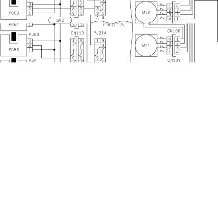
1156SBT0303A
3-3. Misfeed Clearing Procedures
1156SBT030301A
1) Copier Paper Take-Up Misfeed
Relevant Electrical Parts
D 2nd Drawer Paper Take-Up Sensor PC57 |
D 1st Drawer Paper Take-Up Motor M11 |
D 1st Drawer Vertical Transport Sensor PC63 |
D 2nd Drawer Paper Take-Up Motor M12 |
D 2nd Drawer Vertical Transport Sector PC64 |
D Paper Transport Clutch CL1 |
D Transport Roller Sensor PC54 |
D Power Supply Board PWB−C |
|
D Master Board PWB-A |
|
|
1156C01TAA
T-24
!Copier Paper Take-Up Misfeed Clearing Procedure
Symptom |
Step |
Check Item |
Result |
Action |
|
|
|
|
|
D Paper is not taken |
|
Does the paper being used |
|
Instruct the user to use the |
up at all. |
1 |
meet product specifica- |
NO |
paper that meets product |
|
|
tions? |
|
specifications. |
D Paper is stationary |
|
Is the paper curled, waved, |
|
Change the paper. Instruct |
before the Paper |
2 |
or damp? |
YES |
the user in how to store the |
Take-Up Sensor. |
|
|
|
paper. |
|
|
Is the Trailing Edge Stop or |
|
Position the edge stop and |
|
3 |
Edge Guide in good posi- |
NO |
guide to meet the paper |
|
|
tion? |
|
size. |
|
|
|
|
|
|
|
Are the Paper Take-Up Roll |
|
Clean or change the Paper |
|
4 |
and Separator Roll de- |
YES |
Take-Up Roll and/or Sepa- |
|
formed, worn, or dirty with |
rator Roll. |
||
|
|
|
||
|
|
paper dust? |
|
|
|
|
|
|
|
|
|
Is the Paper Take-Up Motor |
|
Check the motor for over- |
|
5 |
(M11, M12) turning when |
NO |
load. |
|
|
the Start key is pressed? |
|
|
|
|
|
|
|
|
|
Run the “Controller/Board |
YES |
Change PWB-A. |
|
6 |
Check.” Is either of the |
|
|
|
|
Change M11, M12, or |
||
|
malfunction codes C032A |
NO |
||
|
|
and C032B displayed? |
PWB-C. |
|
|
|
|
||
Paper is stationary |
|
Are the Vertical Transport |
|
Clean or change the Verti- |
at the Vertical Trans- |
1 |
Rollers deformed, worn, or |
YES |
cal Transport Rollers. |
port Section. |
|
dirty with paper dust? |
|
|
|
|
|
|
|
|
|
Does PC63 operate proper- |
|
Check the PC63 actuator |
|
|
ly? |
|
for operation and, if it |
|
2 |
Using the IC Port Data |
NO |
checks okay, change PC63. |
|
Check function, make an in- |
|
||
|
|
|
|
|
|
|
put port check on PWB-A |
|
|
|
|
(IC3A) APB6. |
|
|
|
|
|
|
|
|
|
Does PC64 operate proper- |
|
Check the PC64 actuator |
|
|
ly? |
|
for operation and, if it |
|
3 |
Using the IC Port Data |
NO |
checks okay, change PC64. |
|
Check function, make an in- |
|
||
|
|
|
|
|
|
|
put port check on PWB-A |
|
|
|
|
(IC3A) APB7. |
|
|
|
|
|
|
|
|
|
Does PC56 operate proper- |
|
Check the PC56 actuator |
|
|
ly? |
|
for operation and, if it |
|
4 |
Using the IC Port Data |
NO |
checks okay, change PC56. |
|
Check function, make an in- |
|
||
|
|
|
|
|
|
|
put port check on PWB-A |
|
|
|
|
(IC3A) APB3. |
|
|
|
|
|
|
|
|
|
Does PC57 operate proper- |
|
Check the PC57 actuator |
|
|
ly? |
|
for operation and, if it |
|
5 |
Using the IC Port Data |
NO |
checks okay, change PC57. |
|
Check function, make an in- |
|
||
|
|
|
|
|
|
|
put port check on PWB-A |
|
|
|
|
(IC3A) APB4. |
|
|
|
|
|
|
|
Does PC54 operate properly?
6Using the IC Port Data Check function, make an input port check on PWB-A (IC5A) BPB6.
YES |
Change PWB-A. |
|
|
|
|
|
Check the PC54 actuator |
|
NO |
for operation and, if it |
|
checks okay, change PC54. |
||
|
||
|
|
T-25
Symptom |
Step |
Check Item |
Result |
Action |
|
|
|
|
|
Paper is stationary |
|
Does CL1 operate proper- |
|
Check the drive transmis- |
at the Vertical Trans- |
|
ly? |
|
sion path. |
port Section |
7 |
Using the IC Port Data |
YES |
|
|
Check function, set the data |
|
||
|
|
|
|
|
|
|
of PWB-A (IC4A) BPA3 to |
|
|
|
|
“0.” |
|
|
|
|
|
|
|
|
|
Run the “Controller Board |
YES |
Change PWB-A. |
|
8 |
Check.” Is the malfunction |
|
|
|
NO |
Change CL1. |
||
|
|
code “C0321” displayed? |
||
|
|
|
|
|
T-26
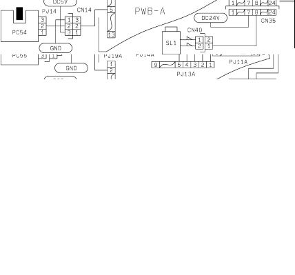
1156SBT030302A
2) Transport/Separator Misfeed
Relevant Electrical Parts
D Transport Roller Sensor PC54 |
D Separator Solenoid SL1 |
D Paper Leading Edge Detecting Sensor PC55 |
D Suction Fan Motor M4 |
D Paper Transport Clutch CL1 |
D High Voltage Unit HV1 |
D Synchronizing Roller Clutch CL2 |
D Master Board PWB-A |
1156C02TAA
T-27
!Transport/Separator Misfeed Clearing Procedure
Symptom |
Step |
Check Item |
Result |
Action |
|
|
|
|
|
|
|
Paper is station- |
|
Is the paper curled, waved or |
|
Change the paper. Instruct |
|
ary at the Syn- |
1 |
damp? |
YES |
the user in how to store the |
|
chronizing Roll- |
|
|
|
paper. |
|
er. |
|
|
|
|
|
|
Does CL2 operate properly? |
|
Check the drive transmis- |
||
|
|
|
|||
|
2 |
Using the IC Port Data Check |
YES |
sion path. |
|
|
function, set the data of PWB-A |
|
|||
|
|
|
|
||
|
|
(IC4A) BPA4 to “0.” |
|
|
|
|
|
|
|
|
|
|
|
Run the “Controller Board |
YES |
Change PWB-A. |
|
|
3 |
Check.” Is the malfunction code |
|
|
|
|
NO |
Change CL2. |
|||
|
|
“C0320” displayed? |
|||
|
|
|
|
|
|
|
|
Is an adequate length of loop |
|
Adjust the loop length using |
|
|
4 |
formed before the Synchroniz- |
NO |
the “Loop Adjust (Drawer)” |
|
|
ing Roller? |
function of “Tech. Rep. |
|||
|
|
|
|||
|
|
|
|
Choice.” |
|
|
|
|
|
|
|
|
|
Does PC55 operate properly? |
YES |
Change PWB-A. |
|
|
|
Using the IC Port Data Check |
|
|
|
|
5 |
|
Check the PC55 actuator for |
||
|
function, make an input port |
|
|||
|
NO |
operation and, if it checks |
|||
|
|
||||
|
|
check on PWB-A (IC5A) BPB5. |
|||
|
|
|
okay, change PC55. |
||
|
|
|
|
||
|
|
|
|
|
|
Paper is station- |
1 |
Is the Pre-Image Transfer Guide |
YES |
Correct, clean, or change |
|
ary near the PC |
Plate deformed or dirty? |
the guide plate. |
|||
|
|
||||
Drum. |
|
|
|
|
|
|
Are the Image Transfer/Paper |
|
Clean or change the wires. |
||
|
|
|
|||
|
2 |
Separator Corona wires deterio- |
YES |
|
|
|
|
rated or dirty? |
|
|
|
|
|
|
|
|
|
|
|
Is the paper guide at the Paper |
|
Clean or change the paper |
|
|
3 |
Separator Corona deformed or |
YES |
guide. |
|
|
|
dirty? |
|
|
|
|
|
|
|
|
|
|
|
Are the Synchronizing Rollers |
|
Clean or change the Syn- |
|
|
4 |
deformed, worn, or dirty with pa- |
YES |
chronizing Rollers. |
|
|
|
per dust? |
|
|
|
|
|
|
|
|
|
|
|
Run the “Controller Board |
YES |
Change PWB-A. |
|
|
|
Check.” Is the malfunction code |
|
|
|
|
5 |
|
Change the Image Transfer/ |
||
|
“C031D” or ”C031E” displayed? |
|
|||
|
NO |
Paper Separator Coronas |
|||
|
|
||||
|
|
|
|||
|
|
|
|
Assy or HV1. |
|
|
|
|
|
|
|
Paper is wedged |
1 |
Are the Paper Separator Fin- |
YES |
Clean or change the Paper |
|
at the Paper |
gers deformed or dirty? |
Separator Fingers. |
|||
|
|
||||
Separator Fin- |
|
|
|
|
|
|
Does SL1 operate properly? |
|
Check the drive transmis- |
||
gers. |
|
|
|||
|
Using the IC Port Data Check |
|
sion path. |
||
|
2 |
YES |
|||
|
function, set the data of PWB-A |
|
|||
|
|
|
|
||
|
|
(IC4A) BPA0 to “0.” |
|
|
|
|
|
|
|
|
|
|
|
Run the “Controller Board |
YES |
Change PWB-A. |
|
|
3 |
Check.” Is the malfunction code |
|
|
|
|
NO |
Change SL1. |
|||
|
|
“C0324” displayed? |
|||
|
|
|
|
|
T-28
Symptom |
Step |
Check Item |
Result |
Action |
|
|
|
|
|
|
|
Paper is station- |
1 |
Do the Suction Belts turn when |
NO |
Check the drive gears and |
|
ary on the Suc- |
the Main Drive Motor runs? |
timing belt. |
|||
|
|
||||
tion Belts. |
|
|
|
|
|
|
Does M4 operate properly? |
YES |
Check the Suction Belts. |
||
|
|
||||
|
|
Using the IC Port Data Check |
|
||
|
|
|
|
||
|
2 |
function, set the data of PWB-A |
|
|
|
|
|
Change M4 or PWB-A. |
|||
|
|
(IC4A) BPC2 to “0.” Does M4 |
NO |
||
|
|
|
|||
|
|
then run at full speed? |
|
||
|
|
|
|
T-29
 Loading...