


KOHLER K-142, K-316, K-412, K-470, K-616 Installation Manual
...Installation Guide
Bidet Faucet
K-142, K-316, K-412,
K-470, K-616, K-6814,
K-8247, K-9295, K-10279,
K-10586, K-12286, K-14431,
K-15286, K-15896, K-16132
M product numbers are for Mexico (i.e. K-12345M) Los números de productos seguidos de
M corresponden a México (Ej. K-12345M)
Français, page ªFrançais-1º Español, páginaª Español-1º
1010448-2-F
Thank You For Choosing Kohler Company
We appreciate your commitment to Kohler quality. Please take a few minutes to review this manual before you start installation. If you encounter any installation or performance problems, please don't hesitate to contact us. Our phone numbers and website are listed on the back cover. Thanks again for choosing Kohler Company.
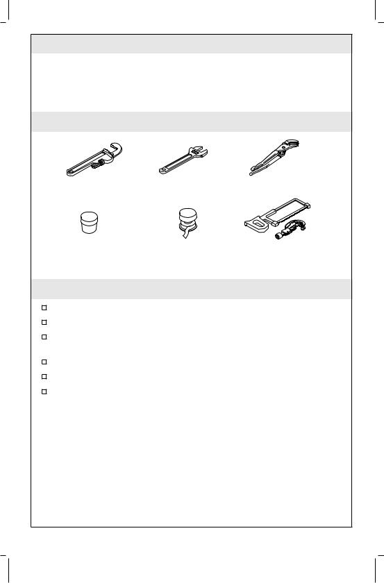
Tools and Materials
Pipe |
Adjustable |
Channel |
Wrench |
Wrench |
Lock Pliers |
Plumbers |
Thread |
Hacksaw or |
Putty |
Sealant |
Tube Cutter |
Before You Begin
Observe all local plumbing and building codes.
Shut off the main water supply.
Carefully inspect waste and supply tubing for any sign of damage.
Replace waste or supply tubing if necessary.
For new installations, install the faucet before installing the bidet.
Kohler Co. reserves the right to make revisions in the design of faucets without notice, as speci®ed within the Price Book.
1010448-2-F |
2 |
Kohler Co. |
|
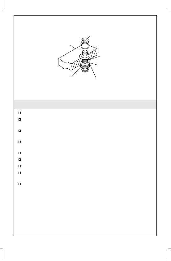
Spray Head |
Bidet |
Flange |
|
|
|
Shank |
|
Rubber |
|
Washer |
Nut |
Metal |
|
|
|
Washer |
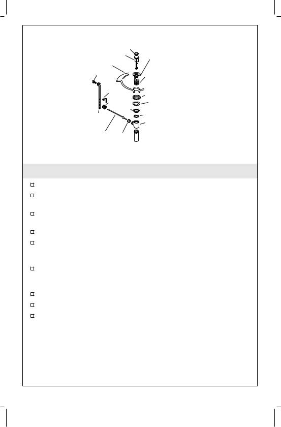
1. Spray Assembly Installation
Remove the spray head and ¯ange.
Thread the nut, metal washer, and rubber washer to the bottom of the shank.
Apply a ring of plumbers putty or other sealant according to the putty manufacturer's instructions.
From the underside of the bidet, insert the shank through the spray hole.
From the top of the bidet, thread the ¯ange onto the shank. Securely thread the spray head as far as it will go onto the shank. Thread the ¯ange until it is snug against the spray head.
Securely tighten the nut onto the shank with a wrench. Do not overtighten.
Remove any excess putty or sealant.
Kohler Co. |
3 |
1010448-2-F |
|
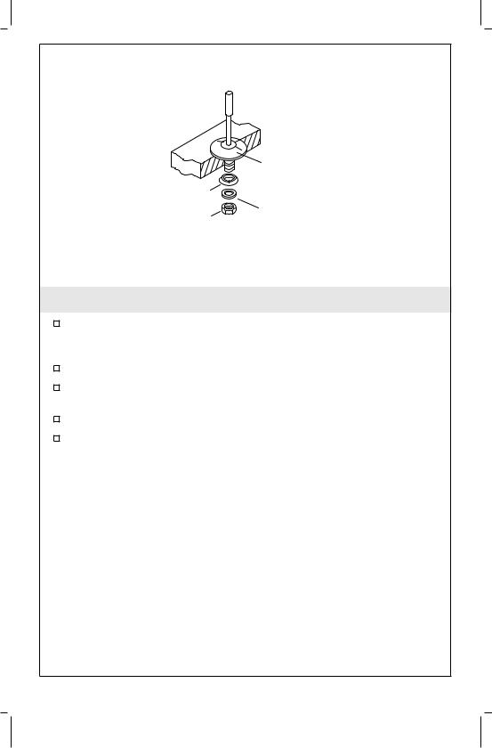
Escutcheon |
|
|
Apply |
|
|
Plumbers |
|
Washer |
Putty. |
|
Nut |
Brass |
|
Washer |
||
|
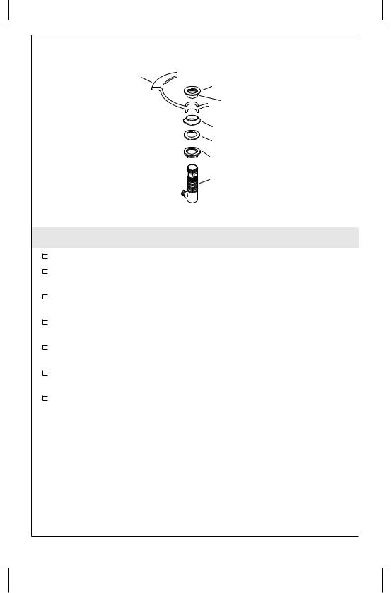
2. Lift Rod Escutcheon Installation
Apply a bead of plumbers putty or other sealant to the underside of the escutcheon according to the putty manufacturer's instructions.
Insert the escutcheon through the mounting hole from above.
From the underside of the bidet, slide the washer (tapered side up), brass washer, and nut onto the escutcheon shank.
Securely tighten the nut with a wrench. Do not overtighten.
Remove any excess putty or sealant.
1010448-2-F |
4 |
Kohler Co. |
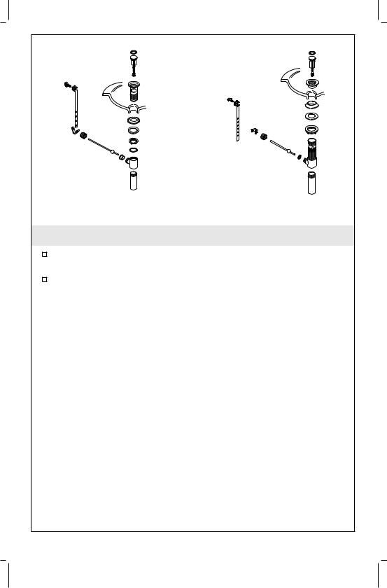
Style A Drain |
Style B Drain |
3. Drain Style
Refer to the illustrations above to determine the drain style you received with your faucet.
Please follow the instructions for your drain style.
Kohler Co. |
5 |
1010448-2-F |
Seal |
Flange |
|
Apply plumbers |
||
Stopper |
putty. |
|
Lavatory |
|
|
Screw |
Apply 3 layers of |
|
Spring |
sealant tape to |
|
bottom 2/3. |
||
Clip |
Gasket |
|
|
||
Nut |
Washer |
|
Nut |
Body Washer |
|
Link |
||
Drain Body |
||
|
||
Rod Seal |
|
4. Drain Installation-Style A
Remove the protective material from the ¯ange.
Wrap the bottom 2/3 of the ¯ange threads with three layers of sealant tape.
Apply a ring of plumbers putty or other sealant to the underside of the ¯ange according to the putty manufacturer's instructions.
Insert the ¯ange into the ®xture drain hole.
Assemble the gasket (tapered side up) and washer to the ¯ange and partially thread the nut to the ¯ange. Do not fully tighten the nut at this time.
Install the body washer and drain body with the seal hole facing the back of the ®xture and securely tighten the nut. Use care to avoid scratching the ®nish.
Remove any excess putty or sealant.
Insert the stopper into the ¯ange.
Insert the seal into the seal hole on the body.
1010448-2-F |
6 |
Kohler Co. |

Stopper
Body Nut
Rod
Seal
Seal Hole
Apply 3 layers of sealant tape and a small bead of pipe sealant to threads.
Faucet
Stopper
Nut
Thumb
Screw
Rod Link
Body
Clip
Tailpiece
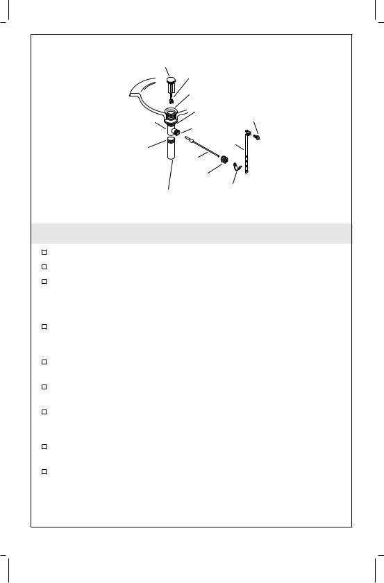
5. Complete Drain Installation-Style A
For regular installations, insert the short end of the rod into the body seal hole and under the stopper. For vandal-resistant installations, ®t the rod through the hole in the stopper. Secure with the body nut.
Remove and adjust the stopper so it lifts about 3/8² (1 cm) when opened. To adjust, loosen the stopper nut and shorten or lengthen the stopper as needed. Tighten the stopper nut.
Apply three layers of thread tape and a small bead of pipe sealant to the tailpiece threads.
Thread the tailpiece to the body and tighten securely.
Slide one end of the clip onto the rod. Slide the link onto the rod with the thumbscrew facing the back of the ®xture.
Squeeze the other end of the clip, aligning the hole with the rod.
Move the link to the proper position by squeezing the clip and sliding it along the rod.
Insert the lift rod into the hole in the faucet and then into the hole in the link.
Tighten the thumbscrew onto the link so the lift rod knob extends above the lift rod hole.
Kohler Co. |
7 |
1010448-2-F |
Fixture
Flange
Apply plumbers putty.
Gasket
Washer
Nut
Drain Body
6. Drain Installation-Style B
Remove the protective cover from the ¯ange.
Apply a ring of plumbers putty or other sealant to the underside of the ¯ange according to the putty manufacturer's instructions.
Assemble the nut, ¯at washer, and tapered gasket (tapered side up) fully onto the body.
From the underside of the ®xture, insert the drain body up into the drain hole.
From the top of the ®xture, securely hand tighten the ¯ange onto the drain body.
Make sure the drain body seal hole is facing the back of the ®xture, and securely tighten the nut.
Remove any excess putty or sealant.
1010448-2-F |
8 |
Kohler Co. |
Stopper
Stopper Rod
Flange |
|
Nut |
Thumb |
Body |
Screw |
Seal |
|
Link
Apply
thread Rod
sealant.
Nut
Clip
Tailpiece
7. Complete Drain Installation-Style B
Press the seal into the seal hole on the body.
Insert the stopper into the ¯ange.
For regular installations, insert the short end of the rod into the body seal hole and under the stopper. For vandal-resistant installations, ®t the rod through the hole in the stopper. Hand tighten the body nut.
Remove and adjust the stopper as needed so it lifts about 3/8² (1 cm) when opened. To adjust, rotate the threaded stopper rod in or out as needed. Retighten the stopper nut.
Apply thread sealant tape to the tailpiece threads, and thread the tailpiece to the body. Tighten the tailpiece securely.
Slide one end of the clip onto the rod. Slide the link onto the rod with the thumbscrew facing the back of the ®xture.
Squeeze the other end of the clip, aligning the hole with the rod. Move the link to the proper position by squeezing the clip and sliding it along the rod.
Insert the lift rod into the hole in the faucet and then into the hole in the link.
Tighten the thumbscrew onto the link so the lift rod knob extends 1/2² (1.3 cm) above the lift rod hole.
Kohler Co. |
9 |
1010448-2-F |

Washer
Dish |
|
End Body |
|
|
|
||
Washer |
|
|
|
Nut |
|
|
|
End Body |
Escutcheon |
|
|
Apply Plumbers |
|
||
Outlet |
|
||
Putty. |
Disc Washer |
||
|
|||
|
|
||
End Body |
|
(When Required) |
|
O-Ring |
|
Washer |
|
|
|
||
Hose |
|
Nut |
8. Handle Valve Installation
Remove and save the dished washer and nut from the valve bodies.
Install a ¯exible hose to each valve body outlet. Tighten securely, but do not overtighten.
Apply a bead of plumbers putty or other sealant to the underside of the escutcheons according to the manufacturer's instructions.
NOTE: The valve body marked ²COLD² with blue lettered tape attached to the tube should be installed to the right of the faucet.
Insert the valve bodies into the proper mounting holes.
From the underside of the bidet, slide a dish washer, washer, and nut onto each valve body.
Rotate each valve body until the copper tubing faces toward the outside of the bidet and the outlets face each other.
Slide a washer and loosely thread a nut onto each valve body.
Firmly hold the valve bodies in place and then securely tighten the nuts with a wrench. Do not overtighten.
Remove any excess putty or sealant.
1010448-2-F |
10 |
Kohler Co. |
Sealing
Washer
|
|
Apply |
|
|
Transfer |
Thread |
|
Compression Sleeve |
Sealant. |
||
Valve |
|||
Nut |
|
|
|
Adapter |
Apply |
Plastic |
|
Thread |
Flexible |
||
|
|||
|
Sealant. |
Hose |
|
|
|
Pipe Fitting |
|
|
Adapter |
|
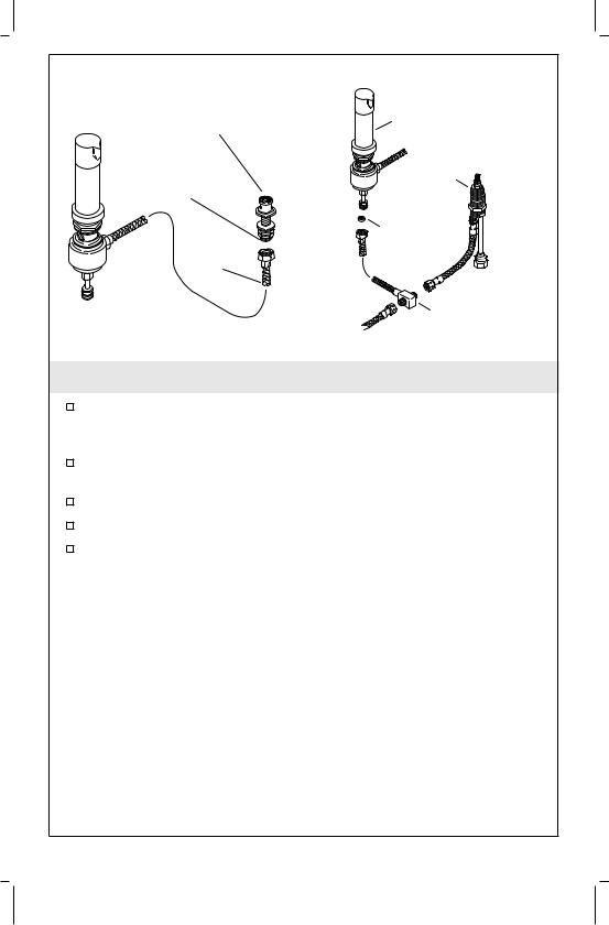
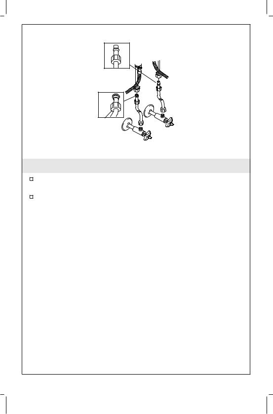
9. Valve/Breaker Installation
Slide the nut and compression sleeve onto the adapter.
Apply thread sealant onto the bottom threads of the adapter. Thread the adapter onto the bottom of the transfer valve shank. Securely tighten the nut.
Apply thread sealant onto the short end threads of the pipe ®tting. Thread the pipe ®tting onto the side of the transfer valve shank.
Apply thread sealant onto the long end threads of the pipe ®tting. Thread the ¯exible hose onto the pipe ®tting.
Slide the sealing washer (tapered side up) onto the transfer valve.
10. Complete Valve/Breaker Installation
From the underside of the bidet, insert the transfer valve into the mounting hole.
From the front of the bidet, rotate the transfer valve until the pipe ®tting faces toward the right.
From the top of the bidet, slide a sealing washer (tapered side down), ¯at washer, and plastic nut onto the transfer valve. Securely hand tighten the plastic nut.
From the front of the bidet, rotate the valve stem counterclockwise. Slide the spline insert onto the valve stem.
Thread the escutcheon onto the plastic nut.
Kohler Co. |
11 |
1010448-2-F |

Complete Valve/Breaker Installation (cont.)
Rotate the handle until the pointer faces the front of the bidet. Press the handle onto the spline insert.
1010448-2-F |
12 |
Kohler Co. |
Transfer Valve/
Spray Head Vacuum Breaker
Assembly
Shank |
End Body |
Apply Thread |
Valve |
Sealant. |
|
Plastic |
Gasket |
Flexible |
|
Hose |
|
Supply Tee
11. Flexible Hose Installation
Apply thread sealant onto the threads of the spray shank. Connect the ¯exible hose from the transfer valve onto the spray shank.
Connect the ¯exible hoses from the end body valve outlets to the supply tee inlets.
Thread a ¯exible hose onto the supply tee outlet.
Slide the gasket onto the transfer valve/vacuum breaker shank.
Connect the ¯exible hose from the supply tee inlet onto the transfer valve/vacuum breaker shank.
Kohler Co. |
13 |
1010448-2-F |
Compression
Union 

Nut
Cold
Hot
12. Supply Connections
Connect the supply tubes to the handle valve (inlets) and then the supply stops. (Left is hot - right is cold.)
Tighten all connections.
1010448-2-F |
14 |
Kohler Co. |
Spout
Aerator
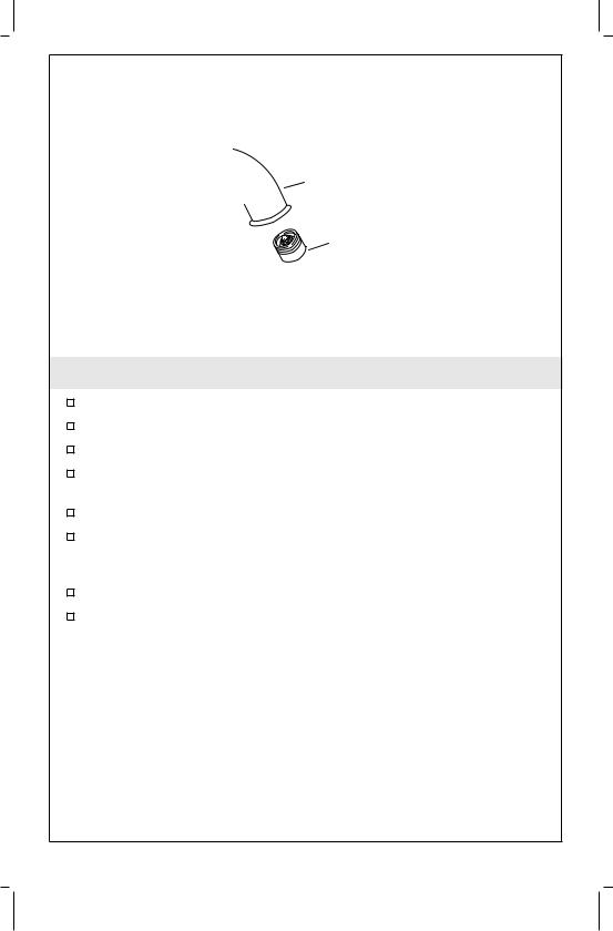
13. Installation Checkout
Connect the tailpiece and P-trap (as needed).
Ensure that all connections are tight.
Open the drain.
Turn on the main water supply and check for leaks. Repair as needed.
Remove the aerator. Point the spray nozzle down.
Open both hot and cold valves and run water through the spout for about a minute to remove debris. Check for leaks. Turn valves off.
Turn off the water.
Remove any debris from aerator and reinstall.
Kohler Co. |
15 |
1010448-2-F |
 Loading...