


Installation Guide
Digital Interface
K-683, K-685 |
K-684, K-686 |
M product numbers are for Mexico (i.e. K-12345M)
Los números de productos seguidos de M corresponden a México (Ej. K-12345M)
Français, page “Français-1” Español, página “Español-1”
1043184-2-B
IMPORTANT INSTRUCTIONS
WARNING: When using electrical products, basic precautions should always be followed, including the following:
DANGER: Risk of electric shock. Connect only to circuits protected by a Ground-Fault Circuit-Interrupter (GFCI) or Earth-Leakage Circuit Breaker (ELCB). Grounding is required. The unit should be installed and grounded by a qualified service representative.
 WARNING: Risk of electric shock. A licensed electrician should route all electrical wiring.
WARNING: Risk of electric shock. Disconnect power before servicing.
WARNING: Risk of injury or property damage. Please read all instructions thoroughly before beginning installation.
NOTICE: Follow all plumbing, electrical, and building codes.
Specifications
Pressures
Maximum Static Pressure |
125 psi, 862 kPa, 8.6 bar |
Supply Pressure Differential* |
Max 5 psi, 34.5 kPa, 0.34 bar (Equal pressures recommended.) |
Minimum Flow Rate |
1.6 gpm (Less than 72 psi dynamic pressure.) |
|
6 lpm (Less than 500 kPa maintaining pressure.) |
|
2.1 gpm (Greater than 72 psi dynamic pressure.) |
|
8 lpm (Greater than 500 kPa maintaining pressure.) |
Temperatures |
|
Programmable Temperature |
Max 120°F (49°C) Min 79°F (26°C) Full cold may also be selected. |
Default Temperature at Start-up |
102°F (39°C) |
Minimum Mixed Temperature |
3.6°F (2°C) |
Differential from Hot Supply |
|
Optimum Thermostatic Control Range |
86°F (30°C) to 120°F (49°C) |
Temperature Stability at Recommended |
+/- 1.6°F (1°C) |
Supply Conditions |
|
Ambient Temperature |
Greater than 34°F (1°C), Max 104°F (40°C) |
Maximum Relative Humidity |
95% non-condensing |
Electrical |
|
Electrical Service |
100-240 VAC, 50-60 Hz, 1.5 A |
User Interface Cable Length (supplied) |
30 ft (9.14 m) |
|
|
* In commercial applications where there is a large difference in hot and cold supply pressures or frequent fluctuation in either supply line is anticipated, it is strongly recommended that pressure regulators be installed.
1043184-2-B |
2 |
Kohler Co. |
Thank You For Choosing Kohler Company
We appreciate your commitment to Kohler quality. Please take a few minutes to review this manual before you start installation. If you encounter any installation or performance problems, please don’t hesitate to contact us. Our phone numbers and website are listed on the back cover. Thanks again for choosing Kohler Company.
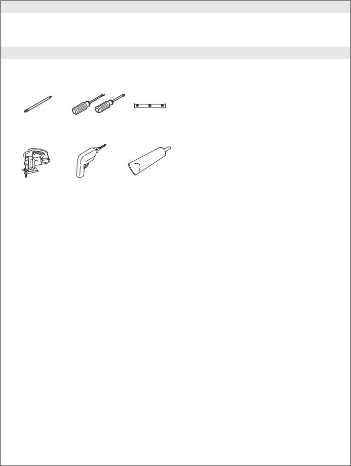
Tools and Materials
|
|
|
Plus: |
|
|
|
• Shims |
Pencil |
Screwdrivers |
Level |
• Suction Cup (Provided) |
|
|||
|
|
|
Jigsaw/Saber |
Drill |
Sealant |
Saw |
|
|
Kohler Co. |
3 |
1043184-2-B |
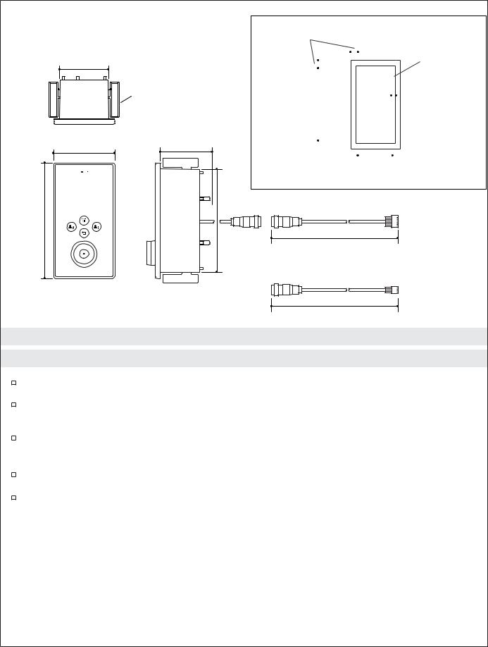
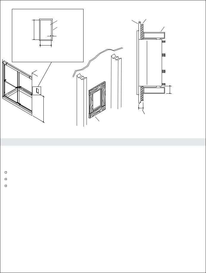
1/2" (1.3 cm) Min Clamp Arm Clearance
3-5/8" (9.2 cm) |
|
|
Clamp Arm |
|
3-5/8" (9.2 cm) – |
|
4-5/8" (11.7 cm) |
4-1/2" (11.4 cm) |
Wall Cavity |
Depth |
8-1/2"
(21.6 cm)
7-5/8"
(19.4 cm)
3/16" (5 mm) Min – 

 2" (5.1 cm) Max Depth
|
|
|
|
|
|
|
|
|
|
Cutout |
|
|
|
|
|
|
|
|
|
|
|
|
|
|
|
|
|
|
|
|
|
|
7-11/16" |
|
|
|
|
|
|
|
|
|
1/4" (6 mm) Min |
|
|
|
|
|
|
|
|
|
||
|
|
|
|
|
|
|
|
|
||
|
|
|
|
|
|
|
|
|||
|
|
|
|
|
|
|
|
|
Interface Lip |
|
(19.5 cm) |
|
|
|
|
|
|
|
|
||
|
|
|
|
|
|
|
Clearance |
|||
|
|
|
|
|
|
|
|
|
|
|
|
|
|
|
|
|
|
|
|
|
|
|
|
|
|
|
|
|
|
|
|
|
|
|
|
|
|
|
|
|
|
|
|
3-11/16" (9.4 cm)
Cutout Detail
8-Pin Interface Cable
30' (9.14 m)
4-Pin Auxiliary Interface Cable
30' (9.14 m)
Roughing-In
Before You Begin
Observe all local plumbing, building, and electrical codes.
Read these instructions and determine all required components along with their installation locations before beginning this installation.
A licensed electrician should install a 120 V GFCI electrical outlet, within the stud framing, in close proximity to the electronic valve. The interface(s) is/are powered through the connection(s) with the valve.
Install the valve prior to installing the interface(s).
Kohler Co. reserves the right to make revisions in the design of faucets without notice, as specified in the Price Book.
1043184-2-B |
4 |
Kohler Co. |
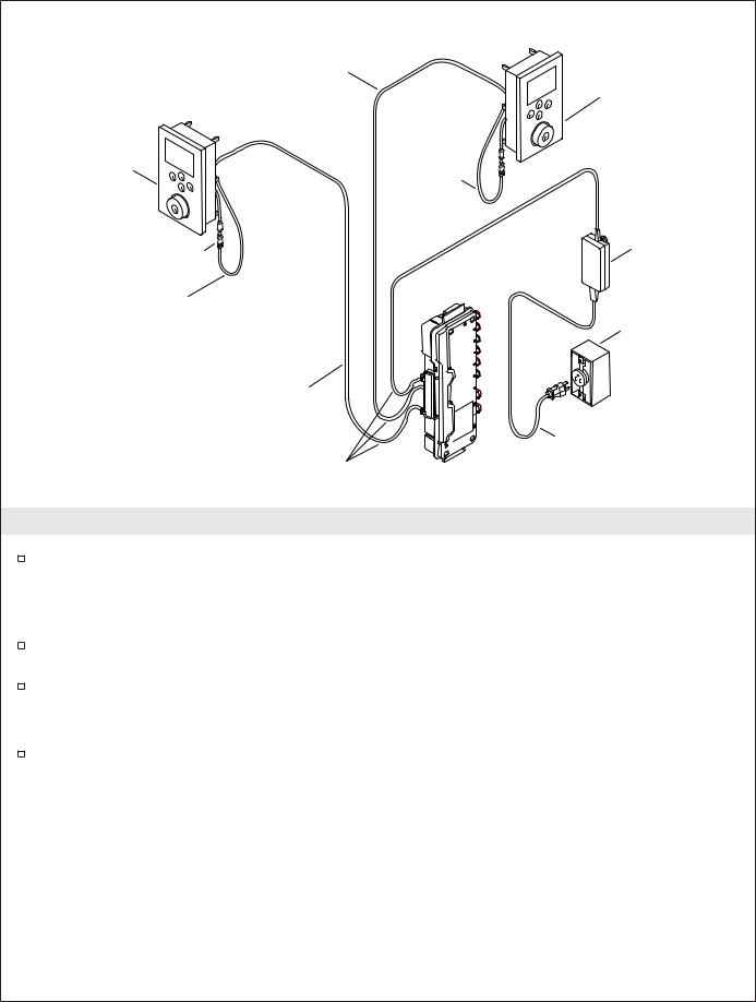
30' (9.14 m) 4-Pin Interface Cable |
Auxiliary Interface |
|
|
|
(Outside Shower) |
Primary Interface
(Inside Shower)
Drip Loop
Power Supply
Connector
Drip Loop
Outlet
30' (9.14 m) 8-Pin Interface Cable
Drip Loop
Drip Loops
1. Preparation
If not already installed, install the digital valve at this time according to the instructions packed with the product.
NOTE: The optional auxillary interface, with the 4-pin cable, is located outside the showering enclosure, while the primary interface, with the 8-pin cable, is located inside the showering enclosure.
Determine all required components along with their installation locations before beginning this installation.
Custom showering experiences other than the preprogrammed options must be programmed into the interface prior to use. Refer to the ″Digital Interface Homeowners Guide.″
NOTE: The 8-pin cable is used for the primary interface and the 4-pin for the auxillary interface.
Verify that both the primary and auxillary interface are located so the interface cable easily spans the distance between the valve and interface connection.
Kohler Co. |
5 |
1043184-2-B |
|
Cutout |
Wall |
Shim |
|
|
||
7-11/16" |
Interface lip |
|
Clamp Arm |
(19.5 cm) |
|
|
|
|
1/4" (6 mm) |
|
|
|
3-11/16" |
|
|
|
(9.4 cm) |
|
|
1/2" (1.3 cm) Min Clamp Arm Clearance
52" (132.1 cm)
3/16" (5 mm) Min –
2" (5.1 cm) Max Depth
2. Prepare the Site
NOTE: Portrait interface shown, landscape interface also available.
NOTE: Allow for a 1/4″ (6 mm) overlap for the lip of the wall sleeve and a minimum clearance of 1/2″ (1.3 cm) around the back of the opening to enable the clips to fully engage.
Refer to the rough-in information. With a pencil, mark the cut lines onto the finished wall.
Carefully cut out the opening in the finished wall following the penciled guidelines.
For thin finished wall materials of less than 3/16″ (5 mm), shim around the back of the opening to provide adequate support for mounting the interface wall sleeve.
1043184-2-B |
6 |
Kohler Co. |

Tuck clamp |
Thinner Wall, 3/16" (5 mm) – |
|
arms into slots. |
||
1-1/4" (3.2 cm) |
Apply silicone sealant.
Flip clamp arms for thicker wall material, 1-1/4" (3.2 cm) – 2" (5.1 cm).
Insert sleeve and untuck clamp arms.
Sleeve |
Interface |
|
|
|
Control |
|
Knob |
Cable
Do not use power screwdriver.
18" |
Secure cable. |
|
(45.7 cm) |
||
Drip Loop |
Min
3. Install the Interface
 CAUTION: Risk of product damage. Do not use power screwdrivers to install the interface.
NOTE: The clamp arms can be removed and turned upside down to allow installation to thicker walls.
Measure the finished wall thickness.
If appropriate, flip the clip arms to accommodate thicker wall materials. Refer to the above illustration.
Secure the interface cable, from the valve, with a zip tie to the back of the wall sleeve allowing approximately 18″ (45.7 cm) of cable to hang free.
Insert the free end of the interface cable into the opening of the wall sleeve.
Tuck the clamp arms into the slots of the sleeve.
Apply a bead of silicone sealant into the groove around the backside of the sleeve lip. Insert the sleeve into the cutout.
Turn the clamp arms so that they are perpendicular to the opening.
Handtighten the screws. Do not overtighten.
Wipe away any excess sealant from around the front of the sleeve. Use care not to get sealant on the outer surface of the sleeve.
Remove the cap from the interface cables.
Connect the interface to the interface cable.
Carefully feed the connection through the hole in the wall sleeve and into the wall cavity. A drip loop will automatically be formed in the cable.
Kohler Co. |
7 |
1043184-2-B |

Install the Interface (cont.)
Verify the gasket is in place on the interface.
Slide the body of the interface into the sleeve.
Firmly press on the interface with the palms of your hands until it snaps into place. Install the control knob.
1043184-2-B |
8 |
Kohler Co. |
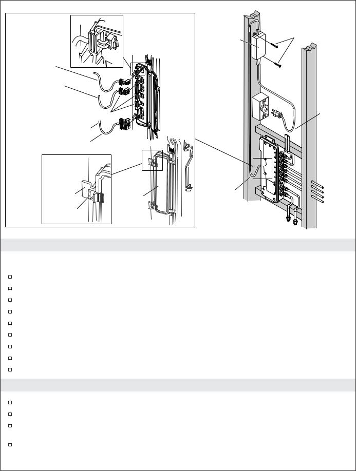
Power Supply |
Screws |
Power Supply
Optional External
Interface Cable
Molded Grommets |
Drip Loop |
|
Internal Interface Cable
Drip Loop
Tab |
Drip Loop |
|
Door |
||
|
||
Clip |
|
4. Complete the Installation
IMPORTANT! Make drip loops in all cables and cords.
Press the clips to release and open the access door on the valve.
Slide the hinge side of the door in either direction until one side slips free.
Remove the door.
Connect the interface cable(s) to the valve.
Connect the power supply to the valve.
Verify all molded grommets are in place before closing the access cover.
Reinstall the access door.
To close the access door, press on the tabs until the clips snap into place.
Plug the power supply into the outlet.
5. Installation Checkout
Turn on the water supply to the valve.
Check all connections for leaks and make any adjustments as needed.
Turn on the main power supply. You should hear the valve power up and the power icon on the user interface will be lit with a green pulsing light.
If not already completed, refer to the ″Digital Interface Homeowners Guide″ to set up the interface.
Kohler Co. |
9 |
1043184-2-B |

Installation Checkout (cont.)
NOTE: For more information about using the user interface and its menus, refer to the user interface Homeowners Guide.
At the main menu of the interface select SHOWER > Options > All On. This will select all connected components and purge the air from the system.
Check for leaks and make any adjustments as needed.
Verify that the water flow is sufficient for your showering needs.
6. Troubleshooting
CAUTION: Risk of personal injury. The valve may contain hot water; be careful when draining any residual water.
IMPORTANT! Turn off the power and water supply to the valve before performing any maintenance.
It is recommended that any valve maintenance should be performed by an authorized Kohler service representative.
This troubleshooting guide is for general aid only. For service and installation issues or concerns, call 1-800-4-KOHLER.
Troubleshooting Table
Symptoms |
Probable Cause |
Recommended Action |
|||
1. |
Control panel is not lit. |
A. |
Power supply is not plugged |
A. |
Plug the power supply into the |
|
|
|
into the outlet. |
|
outlet. |
|
|
B. |
Power supply connection to the |
B. |
Check power supply connections to |
|
|
|
valve may be loose or |
|
the valve and reconnect if needed. |
|
|
|
disconnected. |
|
|
|
|
C. |
Interface cable connections may |
C. |
Check all interface cable |
|
|
|
be loose or disconnected. |
|
connections, connect if needed. |
|
|
D. Circuit breaker has been |
D. Reset the circuit breaker. |
||
|
|
|
tripped. |
|
|
|
|
E. |
The valve memory may require |
E. |
Disconnect and reconnect the |
|
|
|
resetting. |
|
power supply from the valve. |
|
|
F. |
If none of the recommended |
F. |
Contact your Kohler Co. authorized |
|
|
|
actions for the above issues |
|
service representative. |
|
|
|
correct the symptom, the valve |
|
|
|
|
|
or interface requires servicing. |
|
|
2. |
The interface power |
A. |
Interface cable connections may |
A. |
Check all interface cable |
|
indicator pulses but does |
|
be loose or disconnected. |
|
connections, connect if needed. |
|
not turn on. |
|
|
|
|
|
|
B. |
If the above recommended |
B. |
Contact your Kohler Co. authorized |
|
|
|
action does not correct the |
|
service representative. |
|
|
|
symptom, the interface or valve |
|
|
|
|
|
requires servicing. |
|
|
3. |
The interface functions |
A. |
Inlet/outlet fittings may be |
A. |
Check the inlets and outlets for |
|
normally but no water |
|
blocked. |
|
blockage or debris. Clean the inlet |
|
flows from the |
|
|
|
screens. Refer to the ″Clean the |
|
components. |
|
|
|
Inlet Screens″ section in the Valve |
|
|
|
|
|
Homeowners Guide. |
|
|
B. |
Hot and cold water supplies are |
B. |
Turn on the water supply to the |
|
|
|
not turned on. |
|
valve. |
|
|
C. |
The valve memory may require |
C. |
Disconnect and reconnect the |
|
|
|
resetting. |
|
power supply from the valve. |
|
|
D. System error. |
D. Check the user interface for an |
||
|
|
|
|
|
error code. Refer to the |
|
|
|
|
|
″Diagnostics″ section in the Digital |
|
|
|
|
|
Interface Homeowners Guide. |
|
|
|
|
|
|
1043184-2-B |
10 |
Kohler Co. |
Troubleshooting (cont.)
Troubleshooting Table
Symptoms |
Probable Cause |
Recommended Action |
|||
|
|
E. |
If none of the recommended |
E. |
Contact your Kohler Co. authorized |
|
|
|
actions for the above issues |
|
service representative. |
|
|
|
correct the symptom, the valve |
|
|
|
|
|
requires servicing. |
|
|
4. |
Maximum blend |
A. |
Incorrect maximum temperature |
A. |
Refer to the ″Set the Maximum |
|
temperature too hot or |
|
setting. |
|
Temperature″ section in the Digital |
|
too cold. |
|
|
|
Interface Homeowners Guide. |
|
|
B. |
If the above recommended |
B. |
Contact your authorized Kohler |
|
|
|
action does not correct the |
|
service representative. |
|
|
|
symptom, the interface or valve |
|
|
|
|
|
requires servicing. |
|
|
5. |
Continuous flow. |
A. |
System will not switch off. |
A. |
Turn off the water and power |
|
|
|
|
|
supply and contact your Kohler Co. |
|
|
|
|
|
authorized service representative. |
6. |
Massage mode shuts |
A. |
Unequal flow rates between |
A. |
Verify the installation has one |
|
down but water continues |
|
valve outlets. |
|
bodyspray per valve outlet and |
|
to run from |
|
|
|
uses bodysprays with the same |
|
showerhead(s). |
|
|
|
flow rate. If needed, contact the |
|
|
|
|
|
installer to revise the installation. |
|
|
B. |
Fluctuation of inlet pressure. |
B. |
Install pressure regulators in the |
|
|
|
|
|
supply lines. |
|
|
C. |
Pressure difference greater than |
C. |
Install pressure regulators to bring |
|
|
|
5 psi (34.5 kPa) between the hot |
|
the supplies with 5 psi (34.5 kPa) |
|
|
|
and cold supply lines. |
|
of each other. |
7. Only cold water flows |
A. |
Hot water supply is either not |
A. |
Check if the hot water supply is |
|
|
from the outlets. |
|
turned on or not connected to |
|
turned on and connected to the |
|
|
|
the valve inlet. |
|
valve inlet. |
|
|
B. |
Hot water inlet is blocked. |
B. |
Check if the hot water inlet screen |
|
|
|
|
|
for blockage. Clean or replace the |
|
|
|
|
|
inlet screen. Refer to the Valve |
|
|
|
|
|
Homeowners Guide. |
|
|
C. |
If none of the recommended |
C. |
Contact your Kohler Co. authorized |
|
|
|
actions for the above issues |
|
service representative. |
|
|
|
correct the symptom, the valve |
|
|
|
|
|
requires servicing. |
|
|
8. |
Fluctuating or reduced |
A. |
Inlet/outlet fittings may be |
A. |
Check the inlets and outlets for |
|
flow rate. Valve is |
|
blocked. |
|
blockage or debris. Clean the inlet |
|
functioning properly. |
|
|
|
screens. Refer to the ″Clean the |
|
|
|
|
|
Inlet Screens″ section. |
|
|
B. |
Water outlet pressure is low. |
B. |
Check that the flow rate is at or |
|
|
|
|
|
above the minimum rate required. |
|
|
|
|
|
Refer to ″Specifications″ section in |
|
|
|
|
|
the Valve Homeowners Guide. |
|
|
C. |
Fluctuating flow. |
C. |
Verify that the dynamic inlet |
|
|
|
|
|
pressures are within specifications. |
|
|
|
|
|
Refer to ″Specifications″ section. |
|
|
D. If none of the recommended |
D. Contact your Kohler Co. authorized |
||
|
|
|
actions for the above issues |
|
service representative. |
|
|
|
correct the symptom, the valve |
|
|
|
|
|
requires servicing. |
|
|
9. Blend temperature drift or |
A. |
Fluctuating water temperature. |
A. |
Check the inlet temperature |
|
|
temperature cycling. |
|
|
|
differentials and verify they are |
|
|
|
|
|
sufficient. Refer to ″Specifications″ |
|
|
|
|
|
section. |
|
|
B. |
Hot water supply temperature |
B. |
Check and make adjustments as |
|
|
|
fluctuation. |
|
needed. |
|
|
|
|
|
|
Kohler Co. |
11 |
1043184-2-B |
 Loading...