


 Loading...
Safety
User Precautions
•Place the scanner on a sturdy, level work surface capable of supporting 50.8 kg (112 lbs) and leave adequate clearance on all sides of the scanner.
•When relocating the scanner, it is recommended that two people lift the scanner and use safe lifting techniques.
•Do not install the scanner in a location subject to dust, humidity or steam. This may cause electrical shock or a fire. Only use the scanner indoors in a dry location.
•Make sure the electrical power outlet is located within 1.52 meters (5 feet) of the scanner and is easily accessible.
•When disconnecting equipment from the electric socket, be sure to grasp the plug, not the cord.
•Be sure the power cord is securely plugged into the wall outlet. Failure to do so may cause electrical shock or fire.
•Do not damage, knot, cut or modify the power cord or use a damaged power cord. This may cause electrical shock or fire.
•The scanner requires a dedicated and properly grounded power outlet. Do not use an extension cord or power strip with the scanner.
•Do not leave the power cord plugged into the AC outlet if the scanner is not used for an extended period of time.
•Leave sufficient space around the power outlet so it can be easily unplugged in case of an emergency.
•Do not use the scanner if it becomes inordinately hot, has a strange odor, emits smoke, or makes unfamiliar noises. Immediately stop the scanner and disconnect the power cord from the power outlet. Contact Kodak Service.
•Do not disassemble, service or modify the scanner except as explained in the User’s Guide.
•Do not move the scanner with the power cord and interface cable attached. This may cause damage to the cord/cable. Remove the power cord from the wall outlet before moving or relocating the scanner.
•Follow the Kodak recommended cleaning procedures. Do not use air, liquid or gas spray cleaners. These cleaners displace dust, dirt and debris to other locations within the scanner, which may cause the scanner to malfunction.
•Material Safety Data Sheets (MSDS) for chemical products are available on the Kodak website at: www.kodak.com/go/msds. When accessing the MSDSs from the website, you will be required to provide the catalog number or keyword of the consumable you want the Material Safety Data Sheet for. See the section entitled, “Supplies and consumables” later in this guide for supplies and catalog numbers.
Users and their employers need to observe the common sense precautions applicable to the operation of any machinery. These include, but are not limited to, the following:
•Do not wear loose clothing, unbuttoned sleeves, neckties, etc.
•Do not wear loose jewelry, bracelets, bulky rings, long necklaces, etc.
•Hair length should be kept short, using a hair net if needed, or tying long hair up in a bundle.
•Remove all other loose objects from the area that could be drawn into the machine.
•Take sufficient breaks to maintain mental alertness.
•Use only the recommended cleaning supplies.
•Do not use canned/compressed air.
Supervisors should review their employee practices and make compliance with these precautions a part of the job description for operation of the scanner or any mechanical device.

Environmental information
•The Kodak Ngenutiy Scanners are designed to meet worldwide environmental requirements.
•Guidelines are available for the disposal of consumable items that are replaced during maintenance or service; follow local regulations or contact Kodak locally for more information.
•The product packaging is recyclable.
•Kodak Ngenutiy Scanners are Energy Star compliant and shipped from the factory with the default time set to 15 minutes.
European Union
This symbol indicates that when the last user wishes to discard this product, it must be sent to appropriate facilities for recovery and recycling. Please contact your local Kodak representative or refer to www.kodak.com/ go/recycle for additional information on the collection and recovery programs available for this product.
Please consult www.kodak.com/go/REACH for information about the presence of substances included on the candidate list according to article 59(1) of Regulation (EC) No. 1907/2006 (REACH).
Acoustic emission
Maschinenlärminformationsverordnung – 3, GSGV
Der arbeitsplatzbezogene Emissionswert beträgt <70 dB(A).
[Machine Noise Information Ordinance — 3, GSGV
The operator-position noise emission value is <70 dB(A).]
EMC statements
United States
This equipment has been tested and found to comply with the limits for a Class A digital device pursuant to Part 15 of the FCC rules. These limits are designed to provide reasonable protection against harmful interference when the equipment is operated in a commercial environment. This equipment generates, uses, and can radiate radio frequently energy and, if not installed and used in accordance with the instruction manual, may cause harmful interference to radio communications. Operation of this equipment in a residential area is likely to cause harmful interference in which case the user will be required to correct the interference at their own expense.
Japan
This is a Class A product based on the standard of the Voluntary Control Council for interference by information Technology Equipment (VCCI). If this equipment is used in a domestic environment, radio disturbance may arise. When such trouble occurs, the user may be required to take corrective action.
Taiwan
WARNING: This is a Class A product. In a domestic environment this product may cause radio interference in which case the user may be required to take adequate measures.

Peoples Republic of China
WARNING: This is a Class A product. In a domestic environment this product may cause radio interference in which case the user may be required to take adequate measures.
Korea
Please note that this equipment has obtained EMC registration for commercial use. In the event that it has been mistakenly sold or purchased, please exchange it for equipment certified for home use.
European Union
WARNING: This is a Class A product. In a domestic environment this product may cause radio interference in which case the user may be required to take adequate measures.
OVERVIEW |
1-1 |
|
|
INSTALLATION |
2-1 |
|
|
GETTING STARTED |
3-1 |
|
|
CONTROL PANEL AND NGENUITY OPERATOR UTILITY |
4-1 |
|
|
ADVANCED FEATURES |
5-1 |
|
|
MAINTENANCE |
6-1 |
|
|
TROUBLESHOOTING |
7-1 |
|
|
APPENDICES |
A-E |

1 Overview
Contents
Supporting documentation
Supporting documentation .............................................................. |
1-1 |
Optional accessories....................................................................... |
1-2 |
What’s in the box ........................................................................... |
1-2 |
Scanner components ...................................................................... |
1-3 |
Front view ................................................................................... |
1-3 |
Rear view.................................................................................... |
1-7 |
Kodak Ngenuity 9000 Series Scanners offer optimal image quality and scans a wider range of documents than any other scanner in its class. With an easy-to-use operator interface and smart front panel functionality, Ngenuity Scanners are user-friendly and ideal for companies in industries such as health care, financial services,
insurance, government, transportation and service bureaus. These models are available:
•Kodak Ngenuity 9090DC Scanner — duplex scanner that scans 90 pages per minute in color, grayscale or black and white in landscape mode.
•Kodak Ngenuity 9090DB Scanner — duplex scanner that scans 90 pages per minute in black and white or grayscale in landscape mode.
•Kodak Ngenuity 9125DC Scanner — duplex scanner that scans 125 pages per minute in color, grayscale or black and white in landscape mode.
•Kodak Ngenuity 9150DC Scanner — duplex scanner that scans 150 pages per minute in color, grayscale or black and white in landscape mode.
This User’s Guide provides information and procedures for using and maintaining the Kodak Ngenuity 9000 Series Scanners. The information in this guide is for use with all models unless otherwise noted.
The following documentation is available in support of the Kodak Ngenuity 9000 Series Scanners:
•User’s Guide
•Installation Guide
•Maintenance Reference Guide
A-61662 October 2011 |
1-1 |

Optional accessories Front/Rear Printer Kit — front page (pre-scan) and back page (postscan) imprinting prints user-specified alphanumeric strings on the documents as they are scanned. The printer kit includes one printer accessory that can be installed in either the front or rear print position. CAT No. 863 4230
Straight Pass-Through Adapter — this adapter allows you to connect the exit tray to the straight pass-through door for better paper handling. CAT No. 802 9654
What’s in the box
•Kodak Ngenuity 9090DC, 9090DB, 9125DC or 9150DC Scanner
•Power cord bundle
•USB cable
•Camera calibration kit
•Cleaning supplies
•Two Exit Deflectors (one Standard and one Lightweight)
•Installation CD which includes:
-VRS Software
-VRS User Manual and Release notes
-Ngenuity Operator Utility (NOU)
-ISIS/TWAIN Drivers
-User’s Guide
-Installation Guide
-Maintenance Reference Guide
1-2 |
A-61662 October 2011 |

Scanner components
Front view
1
2
3
5 |
4 |
1Control Panel — allows you to initiate scanner functions directly from the scanner.
2Feeder table — place the documents to be scanned on the feeder table. It can be raised and lowered using the feeder table buttons on the control panel.
3Feeder table extender — provides a support for longer documents that extend beyond the standard length. The extender can be pulled out to add approximately 7 inches (18 cm) to the feeder table.
4Side guides — used to guide document(s) into the scanner’s transport. They can be width-adjusted independently, which allows for left-, right-, or center-feeding of documents.
5Feed rollers — contains two rollers that assist in grabbing and feeding documents into the scanner transport. These rollers can be placed in an up position for manual feeding or a down position for automatic document feeding.
A-61662 October 2011 |
1-3 |

9
10
11
8
7
6
6Separator roller door — allows access to the separator roller. The separator roller assists in separating documents as they feed into the transport.
7Scanner cover release lever — there is a transport cover release lever on each side of the scanner. Pull one or both levers towards you to release and open the transport cover.
8Scanner cover — opens in an upward position and will stay open in a full-up position with the support of two gas springs.
9Document output guides — used to guide the scanned document(s) into a neat stack on the exit tray. They can be widthadjusted independently for left-, rightor center-document alignment.
10Exit deflector — assists in the placement of documents in the exit tray. The scanner is packed with 2 exit deflectors. The standard deflector should be used for most of your scanning needs. Use the deeper deflector when scanning light-weight documents (i.e., rice paper.)
Standard Exit Deflector |
Lightweight Exit Deflector |
1-4 |
A-61662 October 2011 |
11Exit tray — where document(s) are deposited after they have passed through the transport. There are two sets of slots that are used for exit tray positioning depending on the types of documents being scanned.
Back of exit tray
 Tabs (slide into
slots)
Top/Front view of scanner - exit tray removed
Slots-
Top row
Bottom row
Stops for bracing kickstand wire
These positions are available:
-Flat: exit tray rests on top of the scanner in a flat, horizontal position, with the tabs on the back of the tray hinged into the bottom row of slots.
-Tilted Forward: tabs at the back of the exit tray are in the top slots causing the exit tray to tilt in a downward position. This position aids stacking of long documents in the exit tray.
-Tilted Backward: tabs at the back of the tray are in the bottom row of slots. Pull the kickstand wire on the bottom of the exit tray down and out. Snap the kickstand wire in the slots of the scanner cover. This is useful when scanning small documents.
NOTES:
•If you have the optional imprinter, there is a door underneath the exit tray that allows access to the front page imprinter.
•If you are using the optional straight pass-through adapter, you can remove the exit tray from its position and place it in the back of the scanner for straight pass-through output. For information on installing and using the straight pass-through adapter, see Appendix C, Installing and Using the Straight Pass-Through Adapter.
A-61662 October 2011 |
1-5 |
12Document stop guide — adjust this guide to match the length of the documents being scanned, which aids in neat document stacking. Slide the document stop guide toward you to lengthen the distance or slide it away from you to shorten the distance.
The document stop guide should be folded down when scanning extra long documents that require the use of the exit tray extender.
NOTE: Positioning the document stop guide too close to the back of the exit tray (towards the back of the scanner) can cause documents to jam as they exit the scanner.
 12
12
13
13Exit tray extender — pull the extender out when scanning longer documents.
A second document stop guide is located on the end of the exit tray extender when scanning extra long documents. When not in use, fold the extender down.
1-6 |
A-61662 October 2011 |

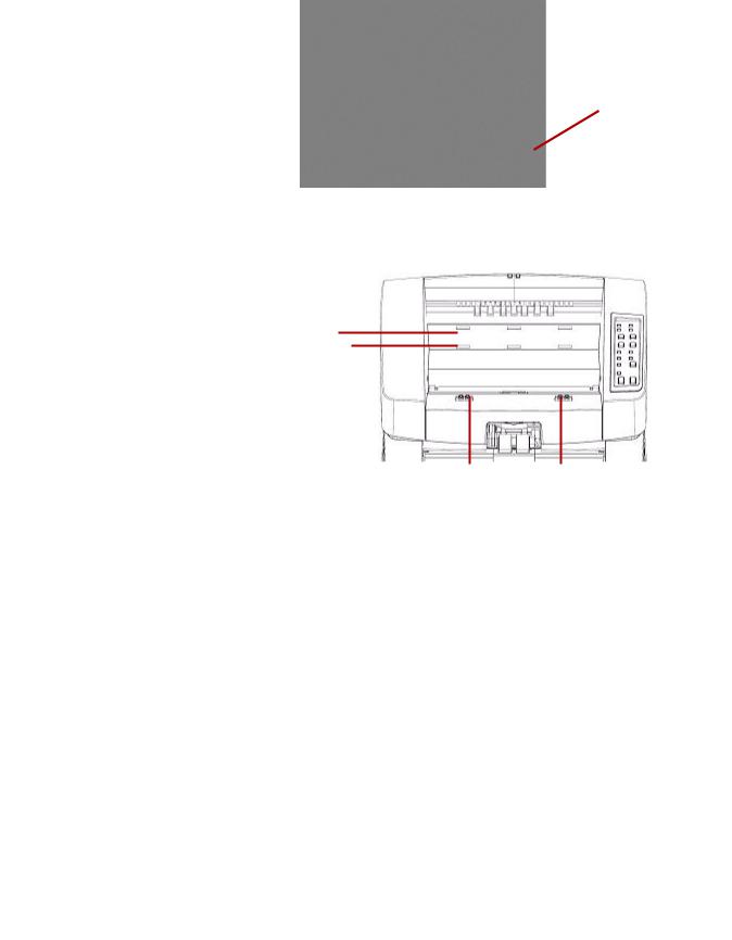
Rear view
1
2
3 |
|
|
|
|
|
8 |
9 |
|
4 |
5 |
6 |
7 |
|||||
|
||||||||
1Imprinter door — provides access to the optional imprinter for installation and maintenance.
2Straight pass-through door — allows you to use the optional straight pass-through adapter. When the door is open and the exit tray is attached, documents are fed through this exit. This is useful for scanning thick or stiff documents. Only open this door when you are using the straight pass-through feature, if the door is opened while scanning in rotary mode, a document jam will occur.
NOTE: When the straight pass-through door is open, the Back Door status light on the control panel will be lit.
3SCSI connector — connects an optional SCSI cable (cable and SCSI card are not provided).
4USB connector — connects the USB cable to the scanner and host PC.
5Fan — for cooling the scanner. The fan is part of the scanner’s power supply. Make sure to properly vent the scanner for optimal performance.
6Power connector — connects the power supply to the scanner.
7Power switch — turns the scanner on (I) and off (O).
8Foot — four rubber feet allow for clearance below the scanner.
9Intake vent (on side) — used for drawing air in for cooling. Be sure to position the scanner in such a way that the intake vent is not blocked.
NOTE: Be sure to maintain an additional 4-5 inches (10-13 cm) of additional clearance at the front, back and sides of the scanner for proper ventilation.
A-61662 October 2011 |
1-7 |

2 Installation
Contents
Installing the exit deflector
Installing the exit deflector .............................................................. |
2-1 |
Installation: with a USB connection ................................................ |
2-2 |
Installation: with an optional SCSI connection ................................ |
2-3 |
This section provides detailed information supporting the Installation Guide that is provided with your scanner. Follow these steps in the order they are provided to install your scanner.
NOTES:
•If you have already performed all of the steps in the Installation Guide, skip this section.
•When positioning the scanner, be sure to provide adequate clearance at the back of the scanner if you will be using the rear document exit. For more information on the rear document exit, see
Appendix C, Installing and Using the Straight Pass-Through Adapter.
•The scanner weighs approximately 112 pounds (50.8 kg). Be sure to incorporate the appropriate manpower before moving or lifting the scanner.
•Verify that your host PC meets the system requirements as specified in Appendix A, Specifications.
•The scanner is packed with a set of language-specific Control Panel overlays. The English overlay is installed on the scanner. If you prefer a different language, take the desired overlay and adhere it to the control panel.
The scanner is packed with two exit deflectors. The exit deflector aids in better document stacking. The standard exit deflector should be used for most of your scanning needs. The lightweight exit deflector should be used when scanning light-weight documents.
•Install the exit deflector by clipping it to the rail at the top of the scanner.
A-61662 October 2011 |
2-1 |
Installation: with a USB connection
If you are using the optional SCSI connection, refer to the next section for installation instructions.
1.Without the scanner attached, turn on the host PC.
2.Load the Installation CD into the CD-ROM drive and install the software in the following order: Ngenuity VRS software first, then the Ngenuity Operator Utility (NOU). You do not need to reboot the host PC after installing each software application.
NOTE: For the latest drivers, go to www.Kodak.com/go/scanners.
3.Power down the host PC.
4.Attach the host PC to the scanner using the supplied USB cable.
5.Turn on the scanner. After the initialization sequence has finished, turn on the host PC.
NOTE: If you are prompted to check for VRS updates, select No.
6.Complete the “Found New Hardware” wizard (twice) to install the USB drivers.
7.Launch the Ngenuity Operator Utility (NOU) by double-clicking the NOU icon  found on the desktop of the host PC.
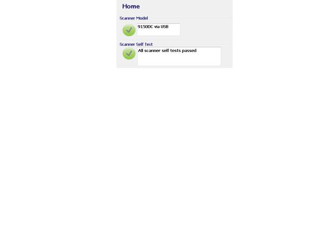
8.Confirm the Ngenuity Operator Utility is communicating with the scanner and all the self tests have passed.
The installation is complete. You are now ready to scan. Refer to the instructions for your scanning application or document management software.
2-2 |
A-61662 October 2011 |

Installation: with an optional SCSI connection
The Kodak Ngenuity Scanner is equipped to accommodate a SCSI connection for communication between the scanner and host PC. The optional SCSI connection can be used in lieu of the standard USB connection.
To use a SCSI connection, a SCSI card and cable is required. Kodak does not provide a SCSI card or cable with the Ngenuity Scanner; therefore, these items must be purchased separately. A SCSI connection kit is not available through Kodak; however, Kodak has certified that Adaptec’s 29160 LP or regular profile card is compatible with Ngenuity Scanners. The SCSI cable must be a D68-pin SCSI-3 cable.
1.Without the scanner attached, turn on the host PC.
2.Load the Installation CD into the CD-ROM drive and install the software in the following order: Ngenuity VRS software first, then the Ngenuity Operator Utility (NOU). You do not need to reboot the host PC after installing each software application.
NOTE: For the latest drivers, go to www.Kodak.com/go/scanners.
3.Power down the host PC and remove the power cord.
4.Install the SCSI card (Adaptec 29160) in the host PC. See the instructions that are included with the SCSI card.
5.Connect the host PC to the scanner.
6.Connect the power to the scanner and reconnect power to the host PC.
7.Turn the scanner on and wait for the initialization sequence to complete.
8.Turn on the host PC.
9.Follow the prompts within the New Hardware Found wizard.
10.Launch the Ngenuity Operator Utility (NOU) by double-clicking the NOU icon  found on the desktop of the host PC.
A-61662 October 2011 |
2-3 |

The Ngenuity Operator Utility Home Screen (default) will update when the scanner self tests have passed and communication with the scanner has been established.
NOTE: If the Ngenuity Operator Utility failed to connect with the scanner, refer to Chapter 7, Troubleshooting for more information.
2-4 |
A-61662 October 2011 |

3 Getting Started
Contents
Getting your scanner ready to scan
Making scanner adjustments
Getting your scanner ready to scan ................................................ |
3-1 |
Making scanner adjustments .......................................................... |
3-1 |
Getting your documents ready to scan ........................................... |
3-2 |
Manually feeding documents .......................................................... |
3-3 |
Accelerated scanning (VRS only) ................................................... |
3-4 |
1.Press the power switch on the back of the scanner to On (I). The control panel indicators will blink a test sequence and the power mode indicator will flash until scanner initialization is complete.
2.After the power mode indicator on the control panel is a steady green, turn on your PC (for SCSI connection only).
NOTE: For more information regarding the control panel, the Ngenuity Operator Control and various scanning modes, see Chapter 4.
Before scanning documents, you may need to adjust your side guides, feeder table extender and exit deflector to accommodate the size of the documents you are scanning.
•The side guides on the feeder table can be moved in and out to accommodate the size of the documents you are scanning.
•If you are scanning documents longer than 11 inches (279.4 mm), pull the feeder table extender out. The feeder table extender will support documents up to 15 inches (381 mm) long.
•To handle longer paper in the exit tray, pull out the exit tray extender. Adjust the position of the exit tray extender so that it will accommodate the length of the documents. The exit tray extender is adjustable to 17 inches (432 mm). When scanning a document longer than 17 inches (432 mm) or A3 size (420 mm), fold down the exit tray extender so that the longer paper will fit in the exit tray.
•If you are feeding thick documents you can use the optional straight pass-through adapter to aid in more efficient document feeding and stacking. See Appendix C, Installing and Using the Straight PassThrough Adapter for more information.
A-61662 October 2011 |
3-1 |

Getting your documents ready to scan
For best scanning results, follow these guidelines:
•Standard paper size documents feed easily through the scanner. When organizing your documents for scanning, stack the documents so the lead edges are aligned and centered in the feeder table. This allows the feeder to introduce documents into the scanner one at a time.
Maximum thickness:
Rotary: .0015 - .035 in. (.038 mm - 0.89 mm)
Straight Pass-Through Door: .0015 - .070 in. (.038 mm - 1.78 mm) Maximum weight: 7 to 320 lbs. (30 to 1,200 g/m2) bond
•Remove all staples and paper clips before scanning. Staples and paper clips on documents may damage the scanner and documents.
•Glued or curled documents may cause a paper jam or damage in the feeder.
•All inks and correction fluids on the paper must be dry before scanning is started.
•Sheets that are exceptionally thick or thin should be placed in the feeder table manually, one sheet at a time, or you can use the optional straight pass-through adapter.
The following types of documents may cause jams or may cause the scanner to feed more than one sheet at a time.
-Overhead projector sheets, plastic films, cloth or metallic sheets
-Paper with irregularities such as tabs, staples, paste and similar items
-Thick or irregular documents such as envelopes or documents that are glued together
-Thermal or heat sensitive paper
-Tracing paper
-Damaged or wrinkled documents
-Photographs
-Coated paper
-Thick plastic cards such as credit cards or identification cards
-Torn sheets and documents with notches, holes, punched or perforated sheets
-Extremely smooth or shiny paper
-Paper that is highly textured
-Paper with carbon sheets
-Carbonless (NCR) paper
3-2 |
A-61662 October 2011 |
Manually feeding documents
For demonstration purposes, VRS Test Application is used in the following procedure.
1.Turn on the scanner and wait until the scanner is ready.
2.Turn on the host PC.
3.Launch the scanning application (in this example, VRS Test Application) and from the Menu bar, select Source>Scanner (Source = 9000 with VRS with AIPE).
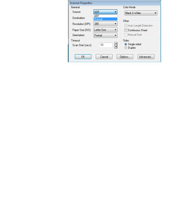
4.When the scanner is connected, select Source>Properties to open the scanning application’s Scanner Properties window.
5.Select Manual from the Source drop-down box.
6.Lift the skimmer to the up position.
7.Remove any paper from the feeder.
8.Start a scan, either single or batch. The feeder table will move up, and the Manual Feed LED will light. The scanner motor will start and beep indicating it is ready for scanning.
9.Carefully insert the page, keeping your hands and fingers away from the rotating tires on the feed rollers. The scanner will feed the page, run it through the scanner and generate an image.
NOTE: If you selected batch scan, you can continue to insert pages, one at a time.
10.When you are finished, press Stop.
A-61662 October 2011 |
3-3 |
Accelerated scanning (VRS only)
If you want to improve the scanning throughput at 300 dpi (or greater), you can change your acceleration scanning setting. To do this:
1.If using Windows 7, from the Taskbar, click the Up arrow to access the Admin Utility.
2.Right-click the VirtualReScan icon.
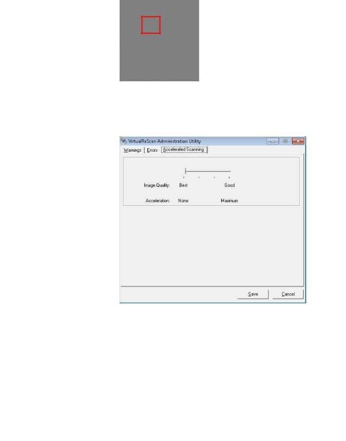
3.Select Admin Utility. The Virtual ReScan Administration Utility dialog box will be displayed.
4.Select the Accelerated Scanning tab.
5.Move the slider bar to Acceleration: Maximum.
6.Click Save.
NOTE: Changing this setting may produce a slight reduction in image quality.
3-4 |
A-61662 October 2011 |
4 Control Panel and Ngenuity Operator Utility
Contents
Control panel................................................................................... |
4-2 |
Status........................................................................................ |
4-3 |
Feeder table.............................................................................. |
4-5 |
Custom functions ...................................................................... |
4-5 |
Scan monitor............................................................................. |
4-5 |
Batch control............................................................................. |
4-7 |
Ngenuity Batch Counter.................................................................. |
4-8 |
Ngenuity Operator Utility................................................................. |
4-8 |
Ngenuity Operator Utility main screen ............................................ |
4-9 |
Menu bar................................................................................. |
4-10 |
Home screen .......................................................................... |
4-13 |
Settings button........................................................................ |
4-15 |
Maintenance button ................................................................ |
4-19 |
This chapter provides detailed information for control panel functionality, a description of the Ngenuity Operator Utility Batch Control application and the Ngenuity Operator Utility (NOU).
A-61662 October 2011 |
4-1 |

Control panel
The control panel is located on the front of the scanner. The LEDs and audible tones notify you of the current state of the scanner (e.g., power state, maintenance needed, active features, errors, etc.).
The control panel has five sections:
•Status
•Feeder table
•Custom functions
•Scan monitor
•Batch control
4-2 |
A-61662 October 2011 |

Status |
The status area of the control panel consists of: Power Mode, Back |
|
Door, Maintenance and Manual Feed. |
|
Power Mode — this green LED indicates the power status or transition |
|
between power modes. |
Power State/Transition Power Mode LED
Off |
Off |
Sleep>Powered up |
Blinking, fast |
|
|
Ready>Active |
Steady green |
|
|
Ready>Sleep |
Blinking, fast |
|
|
Sleep |
Blinking, slow |
When the scanner is in sleep mode, the Power Mode LED is the only indicator that is active; all others are off.
Depending on the current Power Mode, the buttons on the control panel perform different actions. The following table identifies the function of the buttons during various Power Modes and transitions.
Power State/Transition |
Power Mode LED |
Off |
Control panel and scanner are not on. |
|
|
Sleep>Ready |
Buttons are not active during this transition. |
|
|
Ready>Active |
All buttons perform their normal functions. Press and |
|
hold the Stop button for 5 seconds to start the |
|
transition process to put the scanner into sleep |
|
mode. |
|
|
Ready>Sleep |
The scanner is almost ready to go into sleep mode. A |
|
momentary press of any button resets the sleep |
|
count-down timer. |
|
|
Sleep |
A momentary press of any button starts the Sleep > |
|
Awake transition to awaken the scanner. |
|
|
Back Door — this green LED indicates if the straight pass-through door (located at the back of the scanner) is open or closed.
•LED Off: when the straight pass-through door is closed, the rotary path to exit tray is in use.
•LED On: when the straight pass-through door is open, scanned documents will exit through the straight pass-through door.
A-61662 October 2011 |
4-3 |

Maintenance — this yellow LED indicates that maintenance or service conditions exist in the scanner.
Maintenance LED |
Scanner state |
Off (not lit) |
No maintenance is required at this time. |
|
|
Slow blinking |
Maintenance is needed. See the section |
|
entitled, “Ngenuity Operator Utility” |
|
(Maintenance monitor) later in this chapter for |
|
more information. |
|
|
Fast blinking |
Scanner is busy or offline. This occurs when the |
|
scanner is in off-line mode and not capable of |
|
scanning (i.e., ADF test, camera calibration, |
|
downloading firmware, imprinter cleaning, etc.). |
|
|
Steady on |
Scanner self-test fault detected; scanner service |
|
may be required. Use the NOU for more |
|
information on the self test failure. |
|
|
Manual Feed — this green LED indicates that the feed mode has been changed from the default, Normal ADF (Automatic Document Feeder), to Manual feed mode. When the LED is illuminated, the scanner is in Manual feed mode.
Feed modes: the Ngenuity Scanner has four feed modes for feeding documents into the scanner’s transport:
•ADF mode (default) — used for feeding batches of documents that are similar in size and weight. After a batch of documents is placed on the feeder table, the batch is fed automatically into the scanner’s transport.
•Manual mode — this mode is used to feed exception documents that cannot be fed in ADF mode (e.g.,multiple forms). In this mode, you must feed documents manually into the scanner one at a time. When scanning in Manual mode, the Manual Feed LED on the control panel will be lit. See the section entitled, “Manually feeding documents” in Chapter 3 for more information.
•Assisted Manual mode — once the scanner has entered Manual Feed mode, the skimmer can be lowered onto the feeder table to enable Assisted Manual mode. In this mode, the paper sensor on the feeder table will trigger the skimmer to pull the documents into the scanner transport. This mode can also be used to automatically feed small batches while the scanner is in Manual Feed mode.
•Test Feed mode — used to test and verify the scanner’s feeding capabilities, as well as to feed transport cleaning sheets. This mode allows you to feed documents without generating a scan command from the host PC.
Unlike ADF and Manual (Assisted) modes, the Test Feed mode button is set from within Custom Functions in the Ngenuity Operator Utility.
NOTE: With the exception of the Test Feed mode, all feed modes are set through the scanning application’s scanner properties within the scanning software application.
4-4 |
A-61662 October 2011 |

Feeder table |
The Feeder Table adjustment buttons allow you to raise and lower the |
|
|
feeder table to accommodate different batch sizes. The feeder table |
|
|
must be empty to move to a new batch size position. |
|
|
Down/Set |
|
|
• |
Down: lowers the feeder table. |
|
• Set: load a standard batch of documents, lower the skimmer and wait |
|
|
|
until the table is raised. Press and hold the Down/Set button for 2 |
|
|
seconds. |
|
Up — raises the feeder table. If the feeder table has documents in it, |
|
|
the Up button performs no function. |
|
Custom functions |
Two custom functions (F1 and F2) can be assigned via the Ngenuity |
|
|
Operator Utility. Available functions are: Feed Test Batch, Page Eject |
|
|
and Clean Print Head. |
|
|
By default, F1 is assigned to Feed Test Batch and F2 is assigned to |
|
|
Page Eject. See the section entitled, “Ngenuity Operator Utility” later in |
|
|
the chapter for more information. |
|
Scan monitor |
The Scan Monitor indicates that an error has occurred during scanning. |
|
|
The Scan Monitor indicators are lit in yellow. |
|
|
Error — indicates that an error exists that is not covered by one of the |
|
|
other indicators. When an error is indicated, refer to the scanning |
|
|
application for more information. |
|
|
Cover — indicates that the scanner cover is open. Carefully close the |
|
|
scanner cover. |
|
|
If this error occurs during scanning, press Clear/Restart after you have |
|
|
securely closed the cover. |
|
|
Paper Jam — indicates a document jam within the scanner. Open the |
|
|
scanner cover, remove any jammed documents and close the cover. |
|
|
Press Clear/Restart to continue scanning. |
|
|
Misfeed — indicates that a skimmer timeout or feeder jam has |
|
|
occurred. |
|
|
• |
Skimmer timeout: the skimmer is active, but the document to be |
|
|
scanned did not move out of the feeder table (commonly due to roller |
|
|
slippage). |
|
• |
Feeder jam: the document to be scanned is fed but does not reach |
|
|
the scanner transport within the expected transit time. |
A-61662 October 2011 |
4-5 |

Multifeed — when illuminated, indicates multiple or overlapped documents have been detected entering the scanner. This indicator will either momentarily light or remain lit depending on the multifeed condition. For example:
•If the multifeed mode is set to Stop, the indicator remains lit and the scanner stops when a multifeed is detected.
•If the multifeed mode is set to Notify, the indicator will light momentarily along with a sound or prompt for each multifeed that is detected while scanning.
MF Ignore (pre-emptive MF-ignore) — while scanning documents with VRS or direct drivers the MF Ignore button allows you to override multifeed detection to allow exception documents to pass through the scanner without stopping the transport.
There are two options on the Configuration tab of the Advanced Settings dialog box (accessed via the Settings button on the Home screen). These options are:
•Ignore MF Alarm on the Next Page Only (default): if this option is set, you can press the MF Ignore button once to ignore a multifeed alarm on the next document entering the transport. If you press and hold the MF Ignore button, any documents with a potential multifeed condition will be ignored until the button is released.
•Ignore MF Alarm until Feeder Empties: if this option is set, you only need to press the MF Ignore button once to ignore multifed documents. There will be no MF alarms after this button is pressed until the button is pressed again or the feeder is emptied of paper.
NOTE: MF Ignore when using VRS - Interactive Multifeed — the MF Ignore button will allow you to keep the image of the multifed page after it has been displayed on the screen.
For more information, see Chapter 5, Advanced Features.
4-6 |
A-61662 October 2011 |

Batch Control |
The Batch Control buttons allow you to restart and stop scanning. |
Ready — this indicator is illuminated green when the scanner is ready to scan.
•ADF mode: the Ready indicator will light when:
-there are no errors active
-documents are in the feeder
-the skimmer is lowered
-the feeder table has risen (or is rising) to where the skimmer is resting on the documents in the feeder.
•Manual Feed mode: the scanner is ready to scan. The LED will remain a steady green while the scanner is scanning.
Clear/Restart — allows you to clear an error when the error is resolved and resume scanning (e.g., paper is removed from the transport which caused a paper jam).
When using VRS with the Interactive Multifeed feature enabled, use Clear/Restart to clear a multifeed (which tells VRS to discard the multifeed image and rescan the document).
You can also use Clear/Restart to resume scanning after a batch pause.
Pause/Stop — used to stop feeding or stop the scanner’s transport.
•If there is no scan command queued, no documents in the transport, and no feeding in progress, pressing Pause/Stop stops the transport before the automatic transport timeout (20 seconds).
•If the scanner is feeding documents, pressing Pause/Stop once will stop feeding and pause the batch. The Ready LED will blink to indicate when the batch is paused.
•If Pause/Stop is pressed twice or pushed and held for more than one second, a hard stop will occur (scanning stops with documents remaining in the transport) along with a host “scanner stopped” error (this host error will not happen if the scanner is running in Test mode). Press Clear/Restart to resume scanning.
NOTE: If Clear/Restart is pressed before all documents are cleared from the transport, an audible alarm on the scanner will sound and the Paper Jam LED will light. Clear the transport of all documents by pressing and holding the Custom Function button that is programmed for Page Eject and then press Clear/Restart to resume scanning (there is a slight delay before scanning resumes).
•Use Pause/Stop to place the scanner in Sleep mode by pressing and holding the Pause/Stop for 5 seconds or longer. This can only be done when the scanner is idle (no scan commands queued) and the transport is not running.
A-61662 October 2011 |
4-7 |

Ngenuity Batch
Counter
Ngenuity Operator
Utility
The Ngenuity Batch Counter application can be started from
Start>Programs>Kodak>Ngenuity 9000 Scanner>Ngenuity Batch Counter.
This application provides two resettable Batch counters which allow you to keep track of the number of documents scanned in a batch and/ or within a shift.
The top counter can be reset to 0 by clicking the C button next to the counter. The bottom counter (total counter) will not be reset to 0 if the top counter is cleared. To clear both counters, click the C button next to the bottom counter.
The Ngenuity Operator Utility (NOU) is the application that communicates with the scanner to provide scanner status, configure scanner settings and to monitor and assist with performing routine scanner maintenance.
Be sure your scanner is properly connected and the scanner and host PC are on before accessing the Ngenuity Operator Utility.
•From the host PC’s desktop, double-click the Ngenuity Operator Utility icon. The NOU will run through an initialization sequence. When communication with the scanner is established, the scanner and connection type will be displayed on the Home screen of the NOU.
NOTE: Any changes made to NOU settings with the scanner powered off or disconnected from the PC will not be present when the scanner is turned on or reconnected.
4-8 |
A-61662 October 2011 |

Ngenuity Operator Utility main screen
The Ngenuity Operator Utility main screen provides a menu bar and options for configuring basic scanner settings and tasks. The sections that follow provide descriptions of the components on the Home screen including the Menu bar, Home button, Settings button and Maintenance button.
A-61662 October 2011 |
4-9 |
Menu bar
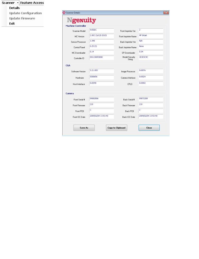
Scanner menu |
Details — displays a Scanner Details dialog box which contains |
|
version information for scanner firmware components and camera |
|
information, as well as scanner model identification. |
•If you click Save As, the Save As dialog box will be displayed allowing you to save this information on the host PC as a text file (.txt).
•Copy to Clipboard allows you to copy the displayed information to the Windows clipboard where you can paste it into another application (e.g., pasting into an email).
•Click Close to close the Scanner Details dialog box.
Update Configuration — allows you to select and download scanner configuration files. For use only as instructed by Kodak Technical Support.
Update Firmware — allows you to select and download scanner firmware updates. Firmware updates should only be performed when instructed by Kodak Technical Support. See www.kodak.com/go/ scanners for any possible updates.
Exit — closes the Ngenuity Operator Utility.
4-10 |
A-61662 October 2011 |
Loading...