


SERVICE MANUAL
for the
MICROWAVE OVEN HOOD COMBINATION
( E Model Line)
March, 1997 |
Printed in U.S.A. |
LIT4317216 |
THIS MANUAL CONTAINS INFORMATION NECESSARY FOR SERVICING THE KITCHENAID MICRO-
WAVE OVEN HOOD COMBINATION , MODELS:
KHMS105E
KHMC107E
THE MANUAL IS DESIGNED TO BE USED ONLY BY
QUALIFIED SERVICE PERSONNEL. THE SERVICE INFORMATION IS ORGANIZED TO HELP YOU EAS-
ILY FIND WHAT YOU NEED.
CHECK YOUR LOCAL BUILDING CODE FOR THE PROPER MODE OF INSTALLATION. IN THE AB-
SENCE OF LOCAL CODES, THIS UNIT SHOULD BE
INSTALLED IN ACCORDANCE WITH THE NATIONAL ELECTRICAL CODE, ANSI/NFPA NO. 70 - 1990, OR
LATEST EDITION, OR C22.1 CANADIAN ELECTRI-
CAL CODE, PART 1.
ii

Microwave Oven Hood Combo Service Manual — LIT 4317216
Original 03/97
Page iii
TABLE OF CONTENTS
Page
Important Safety Information .............................................................................................................. |
v |
Theory Of Operation ......................................................................................................................... |
1-1 |
Component Access ........................................................................................................................... |
2-1 |
Component Sections ................................................................................................................... |
2-1 |
General ............................................................................................................................................... |
2-2 |
Removing The Microwave Oven & Cabinet ............................................................................. |
2-2 |
The Protection Control System ....................................................................................................... |
2-4 |
Removing The Oven Door .......................................................................................................... |
2-4 |
Removing The Door Choke ........................................................................................................ |
2-5 |
Removing The Control Panel ..................................................................................................... |
2-6 |
Removing The Line Fuse ........................................................................................................... |
2-7 |
Removing/Adjusting The Interlock Switches ........................................................................... |
2-8 |
Removing The Base Thermal Fuse ....................................................................................... |
2-11 |
Removing The Magnetron Thermal Fuse .............................................................................. |
2-12 |
Removing The Cavity Thermal Fuse ..................................................................................... |
2-13 |
Removing The Convection Thermistor .................................................................................. |
2-14 |
The Operating Control System ..................................................................................................... |
2-16 |
Removing The Oven Light Socket ......................................................................................... |
2-16 |
Removing The Control Circuit Board ..................................................................................... |
2-17 |
Removing The Temperature Probe Socket .......................................................................... |
2-18 |
Removing The Fan Motor ........................................................................................................ |
2-19 |
Removing The Power Cord ..................................................................................................... |
2-20 |
Removing The Blower Motor Capacitor ................................................................................ |
2-21 |
Removing The Convection Heating Element ........................................................................ |
2-22 |
Removing The Gas Sensor ..................................................................................................... |
2-24 |
Removing The Synchronous Motor ........................................................................................ |
2-25 |
Removing A Cooktop Light Socket ........................................................................................ |
2-26 |
The High Voltage Components .................................................................................................... |
2-27 |
Accessing The High Voltage Components ........................................................................... |
2-28 |
Removing The Magnetron ....................................................................................................... |
2-29 |
Removing The High Voltage Rectifier And The High Voltage Capacitor ......................... |
2-30 |
Removing The High Voltage Transformer ............................................................................ |
2-32 |
iii
|
Page |
Component Description & Testing .................................................................................................. |
3-1 |
Important Safety Instructions ..................................................................................................... |
3-1 |
The Thermal Fuses ..................................................................................................................... |
3-4 |
The Blower Motor Capacitor ...................................................................................................... |
3-5 |
The Gas Sensor ........................................................................................................................... |
3-6 |
The Convection Thermistor ........................................................................................................ |
3-7 |
The Convection Heating Element ............................................................................................. |
3-8 |
Motors ........................................................................................................................................... |
3-9 |
Programming Checks ............................................................................................................... |
3-10 |
Things To Know ........................................................................................................................ |
3-11 |
Charts ......................................................................................................................................... |
3-12 |
Checking The Microwave Power Output ............................................................................... |
3-15 |
Checking For Microwave Energy Leakage ........................................................................... |
3-16 |
Component Testing .................................................................................................................. |
3-19 |
Control Circuit Board Checklist .............................................................................................. |
3-24 |
Primary, Monitor, & Secondary Switch Checkout Procedure ............................................. |
3-25 |
Tech Tips ............................................................................................................................................ |
4-1 |
Wiring Diagrams .......................................................................................................................... |
4-1 |
Strip Circuits ................................................................................................................................. |
4-3 |
Specifications ............................................................................................................................... |
4-7 |
Specification Charts .................................................................................................................... |
4-8 |
Model & Serial Number Explanation ...................................................................................... |
4-12 |
KitchenAid Microwave Hood Warranty .................................................................................. |
4-13 |
iv
Microwave Oven Hood Combo Service Manual — LIT 4317216
Original 03/97
Page v
IMPORTANT SAFETY INFORMATION
This service manual is intended for factoryservice technicians only. We recommend that customers DO NOT service their own units, because of the complexity and risk of highvoltage electrical shock.
The following information is used throughout this manual, and should be read carefully.
NOTE
Helpful information that explains a more complicated step, prior to carrying it out.
 CAUTION
Information that will help you avoid actions that could cause product damage (scratches, dents, etc.) and damage to personal property.
 WARNING
Information that alerts you to potentially dangerous conditions. These conditions can cause serious personal injury (burns, fire and electrical shock, etc.) if the suggested procedures are not observed.
 WARNING
Fire Hazard
Do not obstruct the flow of ventilation air.
Electrical Shock Hazard
It is the customer’s responsibility to:
•Contact a qualified electrical installer.
•Assure that electrical installation is adequate and in conformance with the National Electrical Code, ANSl/NFPA 70— latest edition*, and all local codes and ordinances.
Failure to do so could result in fire, electrical shock, or other personal injury.
Take special care when drilling holes into the wall for venting or electrical wiring. Electrical wires may be concealed behind the wall covering.
Failure to do so could result In fire, electrical shock, or other personal injury.
•National Fire Protection Association Batterymarch Park
Quincy, Massachusetts 02269
KITCHENAID ASSUMES NO RESPONSIBILITY FOR ANY REPAIRS MADE ON OUR PRODUCTS BY ANYONE OTHER THAN AUTHORIZED KITCHENAID SERVICE TECHNICIANS.
v

 CAUTION
 WARNING TO SERVICE TECHNICIANS
To avoid possible exposure to microwave radiation or energy, visually check the oven for damage to the door and door seal before operating the oven. Use your microwave survey meter to check the amount of leakage before servicing. In the event that the R.F. Ieakage exceeds 4 mw/cm2 at 5 cm, appropriate repair must be made before continuing to service the unit. Check interlock function by operating the door latch. The oven cook cycle should cut off before the door can be opened.
The door and latching assembly contains the radio frequency energy within the oven. The door is protected by three safety interlock switches. Do not attempt to defeat them. Under no circumstances should you try to operate the oven with the door open.
•Proper operation of the microwave ovens requires that the magnetron be properly assembled to the waveguide and cavity. Never operate the magnetron unless it is properly installed.
•Be sure the “RF” seal is not damaged, and assembled around the magnetron dome properly when installing the magnetron.
•Routine service safety procedures should be exercised at all times.
•Untrained personnel should not attempt service without a thorough review of the test procedures and safety information contained in this manual.
PRECAUTIONS TO BE OBSERVED BEFORE AND DURING SERVICING TO AVOID POSSIBLE EXPOSURE TO EXCESSIVE MICROWAVE ENERGY.
1.Do not operate or allow the oven to be operated with the door open.
2.Make the following safety checks on all ovens to be serviced before activating the magnetron or other microwave source, and make repairs as necessary:
a)Interlock Operation.
b)Proper Door Closing.
c)Seal and Sealing Surfaces (Arcing, Wear, and Other Damage).
d)Damage to or Loosening of Hinges and Latches.
e)Evidence of Dropping or Abuse.
3.Before turning on microwave power for any service test or inspection within the microwave generating compartments,
check the magnetron, wave guide or transmission line, and cavity for proper alignment, integrity, and connections.
4.Any defective or misadjusted components in the interlock, monitor, door seal, and microwave generation and transmission systems shall be repaired, replaced, or adjusted by procedures described in this manual before the oven is released to the owner.
5.A microwave leakage check to verify compliance with the Federal performance standard should be performed on each oven prior to release to the owner.
6.Do not attempt to operate the oven if the door glass is broken.
vi
Microwave Oven Hood Combo Service Manual — LIT 4317216
Original 03/97
Page vii
 CAUTION
KitchenAid microwave ovens have a monitoring system designed to assure proper operation of the safety interlock systems.
The interlock monitor switch will immediately cause the oven fuse to blow if the door is opened while the following combined failure exists:
Primary door interlock switch and/or secondary interlock switch contacts failed in a closed position.
CAUTION: REPLACE BLOWN FUSE WITH 15 AMPERE CLASS H FUSE ONLY.
Before replacing the blown oven fuse, test the upper and lower door interlock switches, cook relay or latch relay, and interlock monitor switch (middle switch) for proper operation as described in the component test procedures.
DO NOT ATTEMPT TO REPAIR STICKING CONTACTS OF ANY INTERLOCK SWITCH, SAFETY SWITCH, OR COOK (LATCH) RELAY (REPLACE SWITCHES).
Any indication of sticking contacts during component test requires replacement of that component to assure reliability of the safety interlock system.
IF THE FUSE IS BLOWN, THE MONITOR, PRIMARY INTERLOCK AND SECONDARY INTERLOCK SWITCHES MUST ALSO BE REPLACED. BE SURE THEY ARE PROPERLY CONNECTED.
NOTES:
•For proper repair and assembly of the oven door, refer to page 2-4.
•Interlock switches are not adjustable individually.
•For proper repair and adjustment of the interlock switches, refer to page 2-8.
 WARNING
DISCONNECT FROM POWER SUPPLY BEFORE SERVICING.
CAUTION: HIGH VOLTAGES ARE PRESENT DURING THE COOK CYCLE. EXTREME CAUTION SHOULD BE OBSERVED AT ALL TIMES.
CAUTION: DO NOT TOUCH OVEN COMPONENTS OR WIRING DURING OVEN OPERATION. ATTACH METER LEADS WITH ALLIGATOR CLIPS WHEN MAKING OPERATIONAL TESTS.
CAUTION: IT IS NEITHER NECESSARY NOR ADVISABLE TO ATTEMPT MEASUREMENT OF HIGH VOLTAGES.
CAUTION: BEFORE TOUCHING ANY OVEN COMPONENTS OR WIRING, ALWAYS UNPLUG THE OVEN FROM ITS POWER SOURCE AND DISCHARGE THE CAPACITOR BY USING A
20,000-OHM DISCHARGE RESISTOR.
OR
USE AN INSULATED PLASTICHANDLE SCREWDRIVER AND SHORT ACROSS THE CAPACITOR TERMINALS.
vii

R.F. LEAKAGE TEST
 CAUTION
EQUIPMENT
•Electromagnetic energy leakage monitor (NARDA 8100B, HOLADAY H1501).
•600 ml glass beaker.
•Glass thermometer 100°C or 212°F.
TEST
On every service call, checks for microwave energy emission must be made according to the following manner.
1.Remove the cooking rack from the oven cavity, if the microwave oven is so equipped.
2.Place a 250 ML (8.0 oz.) glass of water in the center of the oven bottom.
3.Select “HIGH” cook power, turn the microwave oven on, and test for R.F. Ieakage at the following locations using the pattern shown below:
a)Around the cabinet at the front.
b)Around the door.
c)Across the console panel.
d)Horizontally across the door.
e)Vertically across the door.
f)Diagonally across the door.
g)Across the air vents.
h)Across the rear air vent.
i)All lockseams.
j)Weld at bottom.
k)Bottom plate.
I)Oven feet.
4.The scan speed is one inch per second.
When checking for R.F. Ieakage, use an approved R.F. measuring device to assure less than 4 mw/cm2 emission at 5 cm distance with a maximum scan rate of 2.5 cm/second, in compliance with U.S. Government Department of Health, Education and Welfare 21 CFR1030, performance Standard for Microwave Ovens.
A properly operating door and seal assembly will normally register small emissions, but they must be no greater than 4 mw/cm2 to allow for measurement uncertainty.
NOTE: Enter leakage readings in space BEFORE and AFTER on the service document.
All microwave ovens exceeding the emission level of 4 mw/cm2 must be reported to Dept. of Service for microwave ovens immediately and the owner should be told not to use the microwave oven until it has been repaired completely.
If a microwave oven is found to operate with the door open, report to Dept. of Service, the manufacturer and CDRH* immediately. Also tell the owner not to use the oven.
*CDRH: Center for Device and Radiological Health, Food and Drug Administration.
The interlock monitor switch acts as the final safety switch protecting the customer from microwave radiation. If the interlock monitor switch operated to blow the fuse when the interlocks failed you must replace all interlock switches—primary and secondary interlock switches and the monitor switch with new ones because the contacts of those interlock switches may be melted and welded together.
All repairs must be performed in such a manner that microwave energy emissions are minimal.
Address for CDRH is:
Office of Compliance (HFZ-312) Center for Devices and Radiological Health
1390 Piccard Drive Rockville, Maryland 20850
viii
Microwave Oven Hood Combo Service Manual — LIT 4317216
Original 03/97
Page 1-1
THEORY OF OPERATION
The microwave oven is powered by the 120volt line. Whenever the door is closed and a cooking function is programmed through the control panel’s keypad, relay contacts on the control board close, and complete a circuit from the L1 side to the neutral side of the line.
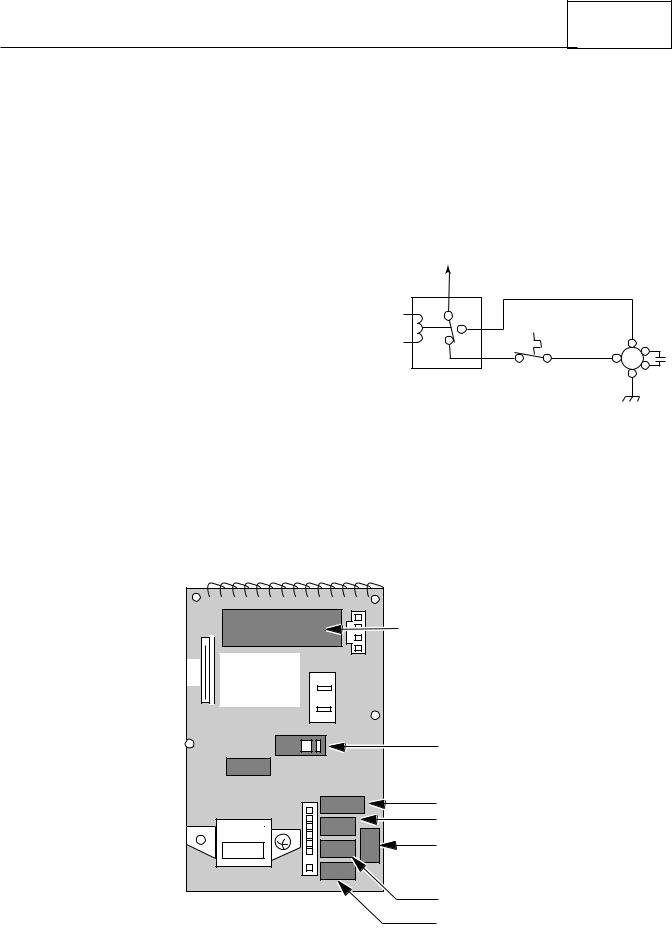
The control board uses six relays to operate the various functions of the microwave oven (shown below). The relays are controlled by the microcomputer on the control board, and perform the functions shown below.
Relay 4 controls the speed of the blower motor through the control panel. The base thermal fuse will also turn the blower motor on to its low speed if the temperature reaches 133˚F. The schematic configuration for relay 4 is shown in the following diagram. The relay is explained in further detail on the following
page.
L1
(C) |
|
|
|
RELAY 4 |
|
BLOWER |
(HI) |
(NO) |
|
MOTOR |
|
|
|
||
(NC) |
|
|
|
|
BASE |
(LOW) |
(C) |
|
|
||
|
THERMAL |
|
|
|
|
|
|
|
FUSE |
|
|
Relay 1 ........................................................ |
Oven Light/Fan & Turntable Motors |
Relay 2 ........................................................ |
High Voltage Section |
Relay 3 ........................................................ |
Low-Speed Blower Motor |
Relay 4 (N.C. Contacts) ........................... |
Auto Low-Speed Blower Motor |
Relay 4 (N.O. Contacts) ........................... |
High-Speed Blower Motor |
Relay 5 ........................................................ |
Cooktop Lights |
Relay 6 ........................................................ |
Night Lights |
|
|
MICROCOMPUTER |
CN3 |
CONTROL |
|
CIRCUIT |
2 |
|
|
BOARD |
1 |
|
|
|
|
|
RELAY RY2 |
|
|
RELAY RY4 |
|
|
RELAY RY3 |
|
|
RELAY RY1 |
|
1 |
|
RELAY RY5
RELAY RY6
1-1
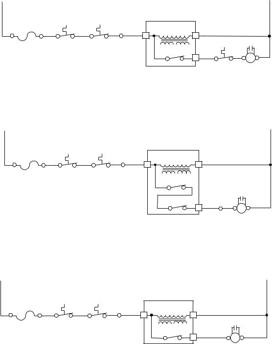
The normally-closed (N.C.) contacts of relay 4 provide a potential circuit for the Base Thermal Fuse (see the following strip circuit). If the base of the oven exceeds 133˚F, the thermal fuse contacts close, and a circuit for the low-speed side of the blower motor is completed, which turns the motor on. The low-speed blower will operate until the base temperature drops below 104˚F and opens the thermal fuse contacts, and turns off.
L1 |
|
|
|
|
|
|
|
|
N |
|
|
|
|
|
MICROCOMPUTER |
|
|
|
|
|
|
|
|
|
BOARD |
|
|
|
|
|
15A LINE |
|
|
|
LOW-VOLTAGE |
|
|
|
|
|
FUSE |
|
|
|
|
|
|
|
|
BK |
BK |
BK RD |
|
TRANSFORMER |
|
W |
|
|
|
BK |
4 |
1 |
|
|
|||||
|
CAVITY |
|
|
|
|
|
|
||
|
MAGNETRON |
|
|
|
|
CAPACITOR |
|||
|
THERMAL |
|
THERMAL |
|
|
|
|
R |
Y |
|
FUSE |
|
FUSE |
|
RELAY #4 |
|
|
||
|
|
|
7 |
YL |
W |
BL |
|||
|
|
|
|
|
|
||||
|
|
|
|
|
|
|
|
|
|
|
|
|
|
|
|
|
BASE |
BLOWER |
|
|
|
|
|
|
|
|
THERMAL |
MOTOR |
|
|
|
|
|
|
|
|
FUSE |
|
LOW |
When the low-speed fan is selected by the user at the control panel, relay 3 and the normallyclosed (N.C.) contacts of relay 4, complete the circuit to the low-speed windings of the blower motor and turn it on.
L1 |
|
|
|
|
|
|
|
N |
|
|
|
|
|
MICROCOMPUTER |
|
|
|
|
|
|
|
|
BOARD |
|
|
|
|
15A LINE |
|
|
|
LOW-VOLTAGE |
|
|
|
|
FUSE |
|
|
|
|
|
|
|
BK |
BK |
BK RD |
|
TRANSFORMER |
|
W |
|
|
BK |
4 |
|
|
|||||
|
CAVITY |
|
|
1 |
|
|
|
|
|
MAGNETRON |
|
|
|
|
|
||
|
THERMAL |
|
THERMAL |
|
|
|
|
|
|
FUSE |
|
FUSE |
|
RELAY #4 |
|
|
|
|
|
|
|
|
|
|
CAPACITOR |
|
|
|
|
|
|
RELAY #3 |
|
R |
Y |
|
|
|
|
|
BR |
W |
BL |
|
|
|
|
|
|
6 |
|||
|
|
|
|
|
|
|
|
|
|
|
|
|
|
|
|
BLOWER |
|
|
|
|
|
|
|
|
MOTOR |
|
|
|
|
|
|
|
|
|
LOW |
When the high-speed fan is selected by the user at the control panel, the normally-open (N.O.) contacts of relay 4 complete the circuit to the high-speed windings of the blower motor and turn it on.
L1 |
|
|
|
|
|
|
|
N |
|
|
|
|
|
MICROCOMPUTER |
|
|
|
|
|
|
|
|
BOARD |
|
|
|
|
15A LINE |
|
|
|
LOW-VOLTAGE |
|
|
|
|
FUSE |
|
|
|
|
|
|
|
BK |
BK |
BK RD |
|
TRANSFORMER |
|
W |
|
|
BK |
4 |
|
|
|||||
|
CAVITY |
MAGNETRON |
1 |
|
|
|
||
|
|
|
|
CAPACITOR |
||||
|
THERMAL |
|
THERMAL |
|
|
|
||
|
|
|
|
|
R |
Y |
||
|
FUSE |
|
FUSE |
|
RELAY #4 |
|
||
|
|
|
BK |
|
BL |
|||
|
|
|
|
|
8 |
|
||
|
|
|
|
|
|
|
|
|
|
|
|
|
|
|
|
BLOWER |
|
|
|
|
|
|
|
|
MOTOR |
|
|
|
|
|
|
|
|
HIGH |
|
1-2
Microwave Oven Hood Combo Service Manual — LIT 4317216
COMPONENT ACCESS
COMPONENT SECTIONS
Original 03/97
Page 2-1
This section instructs you on how to service the individual components in the Microwave Oven Hood Combination. These components (shown below) and their sections are as follows:
•General Cabinet
•The Protection Control System Oven Door
Door Choke Control Panel Line Fuse Interlock Switches
Base Thermal Fuse Magnetron Thermal Fuse Cavity Thermal Fuse Convection Thermistor
CAVITY THERMAL FUSE
GAS SENSOR
(NOT ON ALL MODELS)
CONVECTION THERMISTOR (NOT ON ALL MODELS)
SYNCHRONOUS
MOTOR
COOKTOP LIGHTS
SECONDARY INTERLOCK SWITCH
OVEN LAMP SWITCH
MONITOR SWITCH
PRIMARY INTERLOCK SWITCH
CONTROL CIRCUIT BOARD
LINE FUSE
BASE THERMAL FUSE
•The Operating Control System Oven Light Socket
Control Circuit Board Temperature Probe Socket Fan Motor
Power Cord
Blower Motor Capacitor Convection Heating Element Gas Sensor
Synchronous Motor Cooktop Light Socket
•The High Voltage Components Magnetron
Rectifier Capacitor Transformer
Refer to the section on the following pages for the component you wish to service.
CONVECTION HEATING ELEMENT (NOT ON ALL MODELS)
BLOWER MOTOR
OVEN LIGHT
BLOWER MOTOR
CAPACITOR
 HV TRANSFORMER

 FAN MOTOR
 HV CAPACITOR
 HV RECTIFIER
MAGNETRON
MAGNETRON THERMAL FUSE
Magnetron Thermal Fuse |
..........................................Opens @ 302˚F/150˚C, resets @ 140˚F/60˚C. |
Cavity Thermal Fuse .............................................. |
Opens @ 230˚F/110˚C, resets @ 140˚F/60˚C. |
Base Thermal Fuse ................................................. |
Closes @ 133˚F/56˚C, resets @ 104˚F/40˚C. |
2-1
GENERAL
REMOVING THE MICROWAVE OVEN & CABINET
 WARNING
Personal Injury Hazard
Disconnect from the electrical supply before servicing the unit. Failure to do so could result in death or electrical shock.
CAUTION: Because of the weight and size of the microwave oven, two people are required to safely move and install it. Failure to do so could result in personal injury.
1.Disconnect the electrical supply to the microwave oven.
2.Remove the six screws from the base plate and remove it.
3.Pull the connectors off the cooktop light socket terminals and set the base plate aside (see the illustration on the next page).
4.Remove the lock pin and washer from the top of the microwave oven.
LOCK PIN &
WASHER
5.Support the front of the microwave oven and remove the two bolts and washers from the top of the oven.
6.Using two people, remove the microwave oven from its mounting location and set it on a protected (padded) work surface.
7.To remove the cabinet from the microwave oven, remove the two inside screws from the top of the cabinet that secure the vent grille to the oven. Pull the top of the vent grille out so the tabs are free of their slots, and lift the bottom to unhook the locking tabs from their slots.
8.Remove the screw from the power cord cover and remove the cover.
9.Remove the remaining screws from the top and rear of the cabinet.
10.Slide the cabinet back and unhook the sides from the tabs, then slide the power cord out of the cabinet, and remove the cabinet.
Proceed to the section for the component you wish to service.
2-2

Microwave Oven Hood Combo Service Manual — LIT 4317216
Original 03/97
Page 2-3
POWER
CORD
CABINET VENT
SCREW GRILLE
SCREWS (2)
VENT
GRILLE
POWER
CORD COVER
CABINET
SCREWS
CABINET
BASE
PLATE
WIRES |
|
|
RED |
(2) RED |
(2) WHITE |
WHITE |
|
BASE PLATE
SCREWS
(6)
COOKTOP LIGHT
ASSEMBLY WIRING
Removing The Cabinet
2-3
THE PROTECTION CONTROL SYSTEM
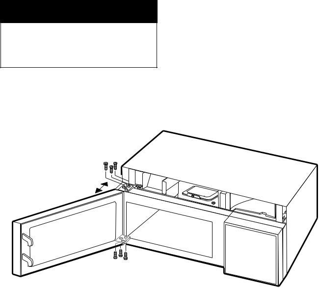
REMOVING THE OVEN DOOR
 WARNING
Personal Injury Hazard
Disconnect from the electrical supply before servicing the unit. Failure to do so could result in death or electrical shock.
CAUTION: Because of the weight and size of the microwave oven, two people are required to safely move and install it. Failure to do so could result in personal injury.
1.Disconnect the electrical supply to the microwave oven.
2.Remove the vent grille and the base plate from the microwave oven (see the illustration on page 2-3).
3.Remove the six oven door hinge screws and remove the door.
4.Install the new oven door and then reassemble the microwave oven.
REASSEMBLY NOTE: Make sure that you open and close the door several times to make sure that it operates properly before you reassemble the oven.
HINGE
MOUNTING
SCREWS
HINGE
MOUNTING
SCREWS
2-4
Microwave Oven Hood Combo Service Manual — LIT 4317216
Original 03/97
Page 2-5
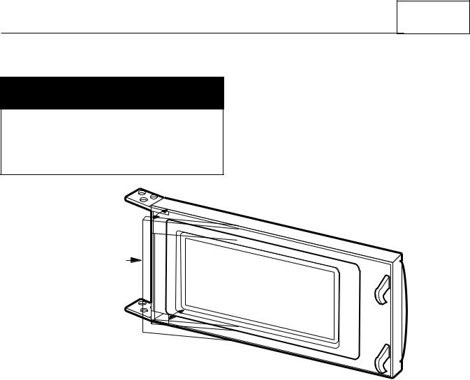
REMOVING THE DOOR CHOKE
 WARNING
Personal Injury Hazard
Disconnect from the electrical supply before servicing the unit. Failure to do so could result in death or electrical shock.
1.Disconnect the electrical supply to the microwave oven.
2.Open the oven door.
3.Pry out the choke (gasket) along the edges of the door with a putty knife and remove the choke.
4.Install the new choke so that it fits tightly into place inside the door.
PRY OUT CHOKE
COLLAR (GASKET)
OVEN DOOR
2-5
REMOVING THE CONTROL PANEL
 WARNING
Personal Injury Hazard
Disconnect from the electrical supply before servicing the unit. Failure to do so could result in death or electrical shock.
1.Disconnect the electrical supply to the microwave oven.
2.Remove the two screws from the top of the cabinet for the vent grille and remove
the grille (see the illustration on page 2-3).
3.Remove the screw from the top center tab of the control panel.
4.From the top and back of the control panel, lift the top locking tab and pull the top of the panel out slightly, then lift the bottom tabs of the panel out of the slots and pull it forward. Turn the panel over out of the way.
|
|
|
MOUNTING |
|
|
TOP |
|
SCREW |
|
|
LOCKING |
|
|
|
CONTROL |
TAB |
|
TOP CENTER |
|
TURN PANEL OVER |
||||
PANEL |
TAB |
|||
TAB |
TAB |
SLOT |
SLOT |
|
|
||||
|
|
|||
|
1 |
|
|
|
|
BOTTOM |
|
BOTTOM |
|
|
|
SLOTS |
||
|
TABS |
|
||
|
|
|
||
|
2-6 |
|
|
|
Microwave Oven Hood Combo Service Manual — LIT 4317216
Original 03/97
Page 2-7
REMOVING THE LINE FUSE
 WARNING
Personal Injury Hazard
Disconnect from the electrical supply before servicing the unit. Failure to do so could result in death or electrical shock.
1.Disconnect the electrical supply to the microwave oven.
2.Remove the two screws from the top of the cabinet for the vent grille and remove the grille (see the illustration on page 2-3).
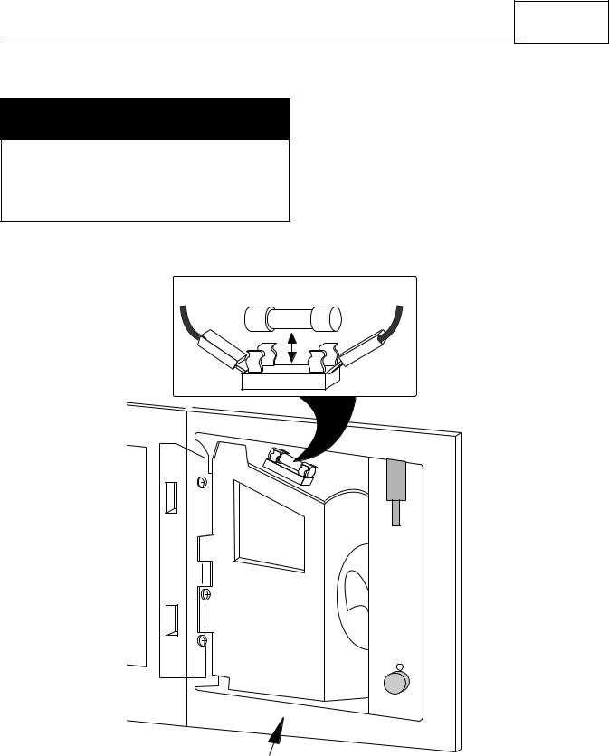
3.Remove the control panel from the microwave oven (see page 2-6).
4.Without touching the metal ends, unsnap the line fuse from its holder.
5.Install the new line fuse in the fuseholder and then reassemble the microwave oven.
LINE FUSE |
BLACK POWER |
CORD LEAD |
FUSEHOLDER
CONTROL PANEL
OPENING
2-7
REMOVING/ADJUSTING THE INTERLOCK SWITCHES
 WARNING
Personal Injury Hazard
Disconnect from the electrical supply before servicing the unit. Failure to do so could result in death or electrical shock.
REMOVING A SWITCH
1.Disconnect the electrical supply to the microwave oven.
2.Remove the two screws from the top of the cabinet for the vent grille and remove
the grille (see the illustration on page 2-3).
3.Remove the screw from the top center tab of the control panel (see page 2-6).
4.From the top and back of the control panel, lift the top locking tab and pull the top of the panel out slightly, then lift the bottom tabs of the panel out of the slots and pull it forward. Set the panel inside the oven cavity while you work.
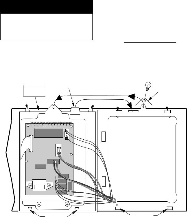
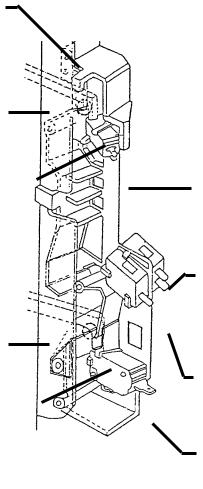
5.Remove the center screw from the fan cover and fold the cover back so you can access the switches (see the illustration below).
6.Remove the two mounting screws from the interlock switch assembly, and position the assembly so you can easily access the switches and wiring.
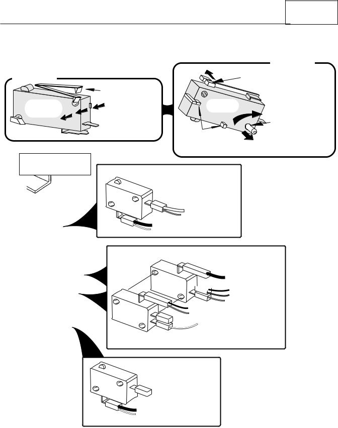
7.Refer to inset 1 in the illustration on the next page for the secondary interlock switch, or inset 2 for any of the other switches mounted on the interlock switch housing assembly, and remove the switch from the housing as shown.
8.One at a time, pull the wire connectors off the defective switch, and reconnect them to the same terminals on the replacement switch.
9.Snap the new switch into place on the switch housing.
10.Mount the interlock switch assembly and then reassemble the microwave oven.
NOTE: If any adjustments are necessary, refer to page 2-10.
|
INTERLOCK |
|
|
SCREW |
|
INTERLOCK |
FAN COVER |
|
SWITCH |
||
|
||
HOUSING |
COVER |
|
|
SCREW |
|
|
FOLD |
|
|
BACK |
|
|
INTERLOCK |
|
|
SCREW |
2-8
Microwave Oven Hood Combo Service Manual — LIT 4317216
Original 03/97
Page 2-9
INSET 2
INSET 1
|
1. RAISE THIS LOCKING |
|
ARM TO RELEASE |
|
SWITCH FROM HOUSING. |
SECONDARY |
2. PRESS BODY IN |
INTERLOCK |
THIS DIRECTION TO |
SWITCH |
REMOVE SWITCH |
|
FROM HOUSING. |
1.PUSH THIS LOCKING ARM BACK TO UNLOCK
SWITCH.
ALL OTHER
SWITCHES
2. ROTATE SWITCH ON THIS  PIN AND REMOVE
SWITCH FROM HOUSING.
NOTE: THESE POSTS
HOLD THE SWITCH IN PLACE ON THE HOUSING AND ARE STATIONARY.
INTERLOCK SWITCH
HOUSING ASSEMBLY
SECONDARY INTERLOCK
SWITCH
WHITE (H.V. Transformer)
RED (Monitor Switch)
 LARGE WHITE (Power Cord)
SMALL WHITE (Oven Lamp)
OVEN LAMP CONTROL
SWITCH
 BLUE (Oven Lamp)

 PINK (Controller)
BLACK (Fan Motor)
RED (Magnetron Thermostat)
 BROWN (Temp Probe)
RED (Secondary Switch)
WHITE (H.V. Transformer)
INTERLOCK MONITOR
SWITCH
PRIMARY INTERLOCK
SWITCH

 PINK (CN2 Pin 1)
 BLUE (Temp Probe)
Blue (CN2 Pin 3)
Interlock Switch Wiring
2-9
MAKING ADJUSTMENTS
1.If necessary, adjust the interlock switch housing so that the switches operate properly. NOTE: The Interlock Monitor Switch provides an added safety check on the Primary and Secondary Interlock Switches. If the Primary and Secondary Interlock Switches allow the oven to operate with the door open, the Interlock Monitor Switch will blow the line fuse.
2.Close and secure the fan cover with its mounting screw.
3.Mount the control panel to the oven with the screw you removed earlier.
4.Mount the vent grille to the microwave oven and check out the operation of the switches.
LATCH
HOUSING
DOOR
LATCH
CHECK GAP
HERE
DOOR
LATCH
CHECK GAP
HERE
SECONDARY INTERLOCK SWITCH
OVEN LAMP CONTROL SWITCH
INTERLOCK MONITOR SWITCH
PRIMARY INTERLOCK SWITCH
2-10
Microwave Oven Hood Combo Service Manual — LIT 4317216
Original 03/97
Page 2-11
REMOVING THE BASE THERMAL FUSE
 WARNING
Personal Injury Hazard
Disconnect from the electrical supply before servicing the unit. Failure to do so could result in death or electrical shock.
1.Disconnect the electrical supply to the microwave oven.
2.Remove the two screws from the top of the cabinet for the vent grille and remove the grille (see the illustration on page 2-3).
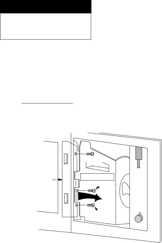
3.Remove the control panel from the microwave oven (see page 2-6 for the procedure).
4.Remove the mounting screw from the base thermal fuse and remove it.
5.Unplug the wire connectors from the base thermal fuse terminals.
6. |
CONTROL |
PANEL |
Install the new base thermal fuse and then reassemble the microwave oven.
MOUNTING
SCREW 
BROWN & WHITE
WIRES 
|
BASE |
TAB |
|
YELLOW |
SLOT |
||
THERMAL |
|||
|
|||
WIRE |
|
||
FUSE |
|
||
|
|
||
THE BASE THERMAL FUSE |
|
|
|
CLOSES @133˚F & RESETS @ 104˚F. |
|
|
2-11
 Loading...