


XG-8000
Table of contents
 Loading...
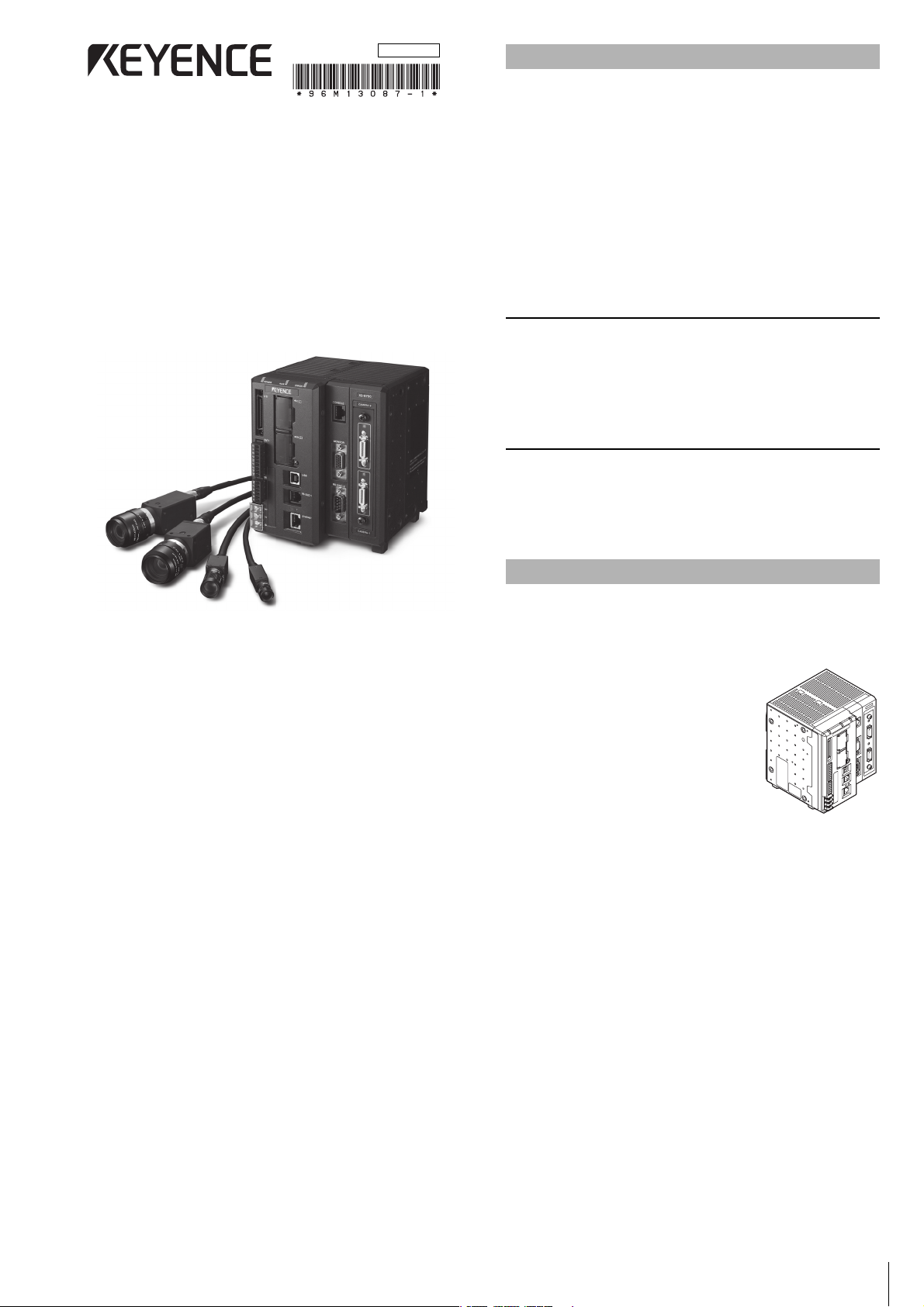
1
Multi Camera High Performance Machine
Vision System
XG-8000 Series
Controller Instruction Manual
Read this manual thoroughly before using the XG-8000 Series.
Always keep this manual in a safe place for future reference.
This manual describes the hardware information. Read this manual
thoroughly to understand the performance and functions of the “Multi
Camera High Performance Machine Vision System XG-8000 Series”
in order to maximize the performance of the system.
• This manual covers the XG-8000 Series. All references, unless
otherwise noted, pertain to the XG-8000(P)/8002(P)/8500(P)/
8502(P)/8700(P)/8702(P)/8800(P)/8802(P)/8500L(P)/8502L(P)/
8700L(P)/8702L(P)/8800L(P)/8802L(P). Except when indicated
otherwise, the explanations will use the XG-8700 as the standard.
For more details on the differences between the models, see
“Main Specifications” (page 9).
• Always keep this manual in a safe place for future reference.
• Ensure that the manual is passed to the end user in case of
transfer of the unit.
Trademarks
• “SD Memory Card” is a registered trademark of the SD
association.
• Other company names and product names are registered
trademarks or trademarks of their respective companies.The TM
mark and ® mark are omitted in this manual.
Concerning the Library and Program
libjpeg
Copyright ©1991-2010, Thomas G. Lane.
This software is based in part on the work of the Independent JPEG
Group.
The equipment and accessories listed below are included in the
package when shipped. Upon opening the carton, check that you
have received all of the equipment and accessories listed below.
Standard Package
• Controller Unit x 1
(XG-8000(P)/8002(P)/8500(P)/8502(P)/
8700(P)/8702(P)/8800(P)/8802(P)/
8500L(P)/8502L(P)/8700L(P)/8702L(P)/
8800L(P)/8802L(P), whichever is
appropriate)
•SD card
(XG-8000(P)/8002(P)/8500(P)/8502(P)/
8500L(P)/8502L(P): OP-87133(512MB),
XG-8700(P)/8702(P)/8800(P)/8802(P)/
8700L(P)/8702L(P)/8800L(P)/8802L(P):
CA-SD1G (1GB)) x 1
(already installed in the SD card slot (lower) of the controller)
• Controller instruction manual (This manual: one part Japanese,
one part English)
• Terminal block sticker package x 1
• Ferrite core for RS-422 use x 1 (only for the XG-8500L(P)/
8502L(P)/8700L(P)/8702L(P)/8800L(P)/8802L(P))
Introduction
Package Contents
96M13087
2
Symbols
The following warning symbols are used to ensure safety and to prevent
human injury and/or damage to property when using the system.
Warning
Indicates that the operator is at risk of physical injury if the system is
improperly operated or this precaution is not followed.
Caution
Indicates that property could be damaged (product malfunction, etc.)
if the system is improperly operated or this precaution is not
followed.
Indicates important operating procedures that could be easily
overlooked.
It indicates tips for better understanding or useful information.
General Cautions
• Before starting work or before starting the system, confirm that all
the functions of the system are working properly.
• If any KEYENCE product fails, take full safety measures to prevent
damage before using the system again.
• If the system is used beyond published specifications or if the
system is modified, the functions and performance cannot be
guaranteed.
• Please note that when the system is used in combination with
other instruments, its functions and performance may be
degraded.
• Do not use this product for the purpose to protect a human body
or a part of human body.
• This product is not intended for use as explosion-proof product.
Do not use this product in hazardous location and/or potentially
explosive atmosphere.
• Do not subject this unit or connected devices to a sudden change
of temperature, as condensation may occur.
Warning
General
• Do not use with any power voltage other than 24 V DC. Doing so
may cause fire, electric shock, or product malfunction.
• Do not disassemble or modify this unit. Doing so may cause fire or
electric shock.
Operating environment and conditions
• To use the system properly and safely, avoid installing this unit in
the following locations: Doing so may cause fire, electric shock, or
product malfunction.
– Locations that contain moisture or dust, or that are poorly
ventilated.
– Locations where the system is exposed to direct sunlight or
temperature increases.
– Locations where there are flammable or corrosive gases.
– Locations where the unit may be directly subjected to vibration
or impact.
–
Locations where water, oil or chemicals may splash onto the unit.
– Locations where static electricity occurs.
• Keep this unit and cables away from high-tension cables or power
lines. Otherwise, noise may cause malfunction or accidents.
• Bundle cables with a spiral tubing material. Direct bundling will
concentrate the cable load on the bindings, which can result in
cable damage or short circuit.
• This unit and optional devices are precision components. Do not
subject them to vibration or impact.
Measures to be taken when an abnormality occurs
In the following cases, turn the power OFF immediately. Using the
unit in an abnormal condition may cause fire, electric shock, or
product malfunction. Contact your local KEYENCE office for repair.
• If water or debris enters the system
• If the system is dropped or the case is damaged
• If smoke or a burning smell emits from the system
Caution
Usage
• Before making any connections/disconnections, be sure to turn off
the power of this unit and connected devices. Failure to do so may
result in malfunction of the system or connected devices.
• Do not turn the power off while you are programming. Otherwise,
all or part of the program settings may be lost.
• Do not block the ventilation holes. Otherwise, the inside
temperature may rise and malfunction may occur.
• Do not allow an excessive amount of sunlight or bright indoor light
to enter the camera for a long period of time. Doing so may cause
damage to the imaging area inside the camera.
• Do not use the controller, cameras, and options in any
combination other than that specified by Keyence. Doing so may
cause failure or malfunction.
Note
Maintenance
• Do not clean with benzene, thinner, or alcohol.
• Doing so may cause discoloration or deformation of the unit. If the
unit has any dirt on it, wipe it off with a cloth moistened with a mild
detergent, then wipe with a dry cloth.
CE Marking
KEYENCE evaluates compliance with the requirements of the EC
directive according to how products fulfill the below conditions.
KEYENCE has confirmed that the XG-8000 Series meets these
requirements. When the XG-8000 Series is used in EU nations, take
note of the following precautions.
EMC Directive (2004/108/EC)
• Applicable Standard EMI: EN61326-1, Class A
EMS: EN61326-1
• Use cables shorter than 30 m to connect the controller unit and its
external devices.
• When connecting a CC-Link unit CA-NCL10E, attach a ferrite core
(OP-84364, optional) within 300 mm on the CA-CNL10E side of
the CC-Link dedicated cable.
• When using the RS-422, attach the included ferrite core
(ZCAT2035-9030A) within 300 mm on the controller side of the
cable.
• When the XG-8800/8802/8800L/8802L is connected with 5 or
more Ultra-compact cameras (XG-S035C/S035M or XG-S200C/
S200M), attach a ferrite core (OP-87476, optional) to the all
cables from the camera control units to the CCD within 100 mm
on the camera control unit side.
However, these precautions do not guarantee that the customer’s
entire machinery installation is compliant with the EMC Directive.
The customer is responsible for determining the compliance of the
overall machinery installation.
Safety Precautions
Note
Reference
Precautions on Regulations and Standards
3
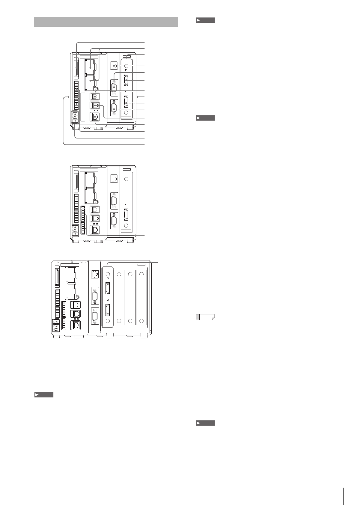
XG-8700/8702/8500/8502/8000/8002
XG-8700L/8702L/8500L/8502L
XG-8800/8002/8800L/8802L
1 Parallel I/O connector
Use to connect the parallel input/output signals.
2 SD2 slot (upper), SD1 slot (lower)
Insert an SD card.
The lower slot (SD1) holds the included SD Card (CA-SD1G: 1GB,
or OP-87133: 512MB) as SD Card 1.
SD Card 1 must be inserted while the device is operating.
3 Camera Slot
Connect the camera input unit.
• The Camera Input Unit (CA-EC80: Area Scan Camera, or
CA-EC80L: Line Scan Camera) is connected to the slot at the
time of shipping.
• The XG-8800(P)/8802(P)/8800L(P)/8802L(P) have 3 free slots.
The user can add camera input units according to need.
• Camera input unit CA-EC80HX cannot be used with the XG-8800L(P).
Camera input unit CA-EC80HX/CA-EC80L/XG-EC80L cannot be used with
the XG-8800(P).
• If the firmware of the camera input unit is old, an error message will be
displayed at the startup of the device (Ver.5.0.0020 or later). In this case,
execute an update with the latest firmware with the camera input unit
attached.
4 CONSOLE (Modular) connector
Use to connect to the console (OP-84231/OP-84236, optional) or to
the console connector cable (OP-87260: 3 m/OP-87261: 10 m,
optional).
5 MONITOR (RGB output) terminal
Use to connect to an Analog RGB Monitor.
• When using a commercially available Analog RGB Monitor other than the
SVGA (800 x 600 pixels), or XGA (1024 x 768 pixels), due to the
specifications of the Monitor, the image quality may become worse or the
screen may not display correctly (recommended monitor: CA-MP120T/
CA-MP120/CA-MP81).
• When a program setting where XGA output is set is used in the main unit,
always connect a monitor that supports the XGA. When using a monitor
that supports the SVGA only, the screen may not display correctly.
6 CAMERA 2 connector (only when CA-EC80/XG-EC80
installed)
Connect Camera 2. When the XG-EC80HX/CA-EC80L/XG-EC80L
is installed only Camera 1 is connected.
7 USB connector
Use to connect to the USB cable.
8 Expansion unit connector 1 (right side)
Use to connect the camera expansion unit CA-E800/XG-E800.
9 CAMERA 1 connector
Use to connect to the camera 1.
10 RS-232C Port 2
Connect the RS-232C Cable for the Touch Panel (OP-87258: 3 m/
OP-87259: 10 m, optional) or a commercially available RS-232C
Cable (D-sub9 Pin female).
11 RS-232C Port 1
Connect the RS-232C Communication Cable (OP-26487: 2.5 m,
optional) or the RS-232C Modular Cable for the Touch Panel
(OP-87264: 3 m/OP-87265: 10 m, optional).
For the default settings of the RS-232C Port: Port 1 is for data output and
command control, and Port 2 is for CA Series Touch Panel use. Concerning
changes in the settings refer to the XG-8000 Series User’s Manual.
12 Ethernet connector
Use to connect the Ethernet cable.
13 OUT1/IN1 Connector (Terminal Block 1)
Use the signal Input/Output (OUT1/IN1).
14 Power Source/Grounding Terminal
Connect the power supply (24 VDC) and the grounding wire.
15 Expansion unit connector 2 (left side)
Use to connect the illumination expansion unit CA-DC30E/DC21E or
CC-Link unit CA-NCL10E.
• The CA-DC30E cannot be connected to the XG-8800(P) or XG-8800L(P).
• When the illumination expansion unit CA-DC20E is connected, flash control
is limited to FLASH1-4.
16 IN2/OUT2 Connector
(Terminal Block 2, XG-8500L(P)/8502L(P)/8700L(P)/8702L(P)/
8800(P)/8802(P)/8800L(P)/8802L(P) only)
Use for the Input/Output signal (IN2/OUT2).
Identifying Controls and Connectors
1
2
4
3
5
6
7
8
9
10
11
12
13
14
15
16
3
Note
Note
Note
Reference
Note
4
Install the controller unit to DIN rail, or use the holes on the bottom of
the controller to secure it with screws.
• Do not install the XG in a location with lots of dust or water vapor. The XG
does not have a mechanism to protect the XG from dust or water. Dust or
water entering the controller can cause damage to the XG.
• Turn off the power to the controller when connecting or removing an
expansion unit, a cable, or a terminal block. Connecting or removing the
camera expansion unit, the cable, or the terminal block while the power is
being supplied may damage the controller or peripheral devices.
• When an expansion unit is not connected, place the connector protection
cover back on the controller. Using the controller with the connector
exposed may cause damage to the controller.
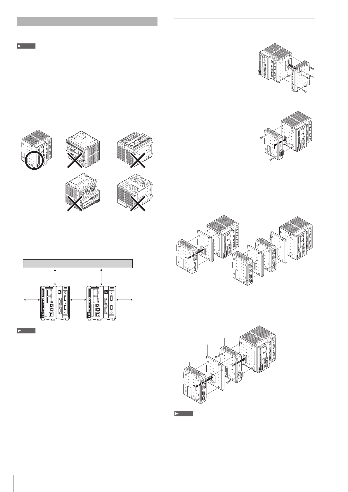
Caution on Direction of Controller Mounting
• Install the controller in the direction indicated by the circle as
shown below. Do not install the controller in any other direction.
• For ventilation, keep the space free of objects for 50 mm or more
above the controller and 50 mm or more for both sides. Keep the
space free of objects for 90 mm or more in the front of the
connector panel to connect the cables safely.
• When two or more controllers are installed side by side, keep the
space free of objects for 50 mm or more between controllers, and
50 mm or more on top of both controllers.
• Do not block the ventilation openings on the top and bottom of the
controller. If the vents are blocked, heat is accumulated inside the machine
and can cause system failure.
• If the temperature inside the control panel (temperature at the upper part of
the front surface of the controller) exceeds the rating, use forced air-cooling
or increase the free space around the system to improve ventilation until the
operating ambient temperature drops below the rating.
Installing the Expansion Unit
Installing the Camera Expansion Unit
(Excluding the XG-8800(P)/8802(P)/8800L(P)/8802L(P))
When connecting three or more
cameras, after connecting the optional
Camera Input Unit to the optional
Camera Expansion Unit CA-E800/
XG-E800, install to the controller.
After detaching the protection sticker
of connector 1 to the right side of the
main controller, install the Camera
Expansion Unit.
Installing the Communication Expansion Unit
The optional CC-Link expansion unit
CA-NCL10E is used when
communicating with CC-Link devices.
Remove the protective cover of
connector 2 from the left side of the
controller and install the CC-Link
expansion unit.
Installing the Illumination Expansion Unit
A combination of up to 4 CA-DC21E and CA-DC30E illumination
expansion units (sold separately) may be connected for control of up
to 8 individual lighting units. However, a maximum of 2 CA-DC30E
units may be connected for control of up to 4 individual lighting units.
Remove the protective cover of connector 2 from the left side of the
controller and install the illumination expansion unit as shown below.
When using the illumination expansion unit and CC-Link unit
simultaneously
Mount the CC-Link unit CA-NCL10E directly to the controller, then
mount the illumination expansion unit to the left side of the CC-Link
unit.
• Turn off the power to the controller when connecting or removing each
expansion unit. Connecting or removing the each expansion unit while the
power is being supplied may damage the controller or peripheral devices.
• When an expansion unit is not connected, place the connector protection
cover back on the controller. Using the controller with the connector
exposed may cause damage to the controller.
• It is necessary to mount the supplied attachments before mounting the
illumination expansion unit.
Installing the Controller Unit
Note
50 mm
50 mm 50 mm
50 mm
50 mm
Note
When connecting
multiple units
OUT
IN
PO
WER
LIGHT 2
4
3
2
1
LIGHT 1
4
3
2
1
OUT
IN
PO
WER
LIGHT 2
4
3
2
1
LIGHT 1
4
3
2
1
Attachment
(Supplied to
the illumination expansion unit)
Illumination
expansion unit
OUT
IN
PO
WER
LIGHT 2
4
3
2
1
LIGHT 1
4
3
2
1
OUT
IN
P
O
WER
LIGHT 2
4
3
2
1
LIGHT 1
4
3
2
1
Attachment (Supplied to
the illumination expansion unit)
Illumination
expansion unit
CC-Link unit
CA-NCL 10E
Note
Loading...