


 Loading...
96M0366
User’s Manual
Visual KV Series
3
Programming
How this manual is organized:
The Visual KV Series User’s Manual is composed of 3 separate manuals; 1-Installation, 2-Support Software, 3-Programming. Please read each manual relevant to your purpose.

Safety Precautions
This instruction manual describes the operation and function of the KV Series PLC. Read this manual carefully to ensure safe use and maximum performance from your KV Series PLC.
Symbols
The following symbols alert you to important messages. Be sure to read these messages carefully.

 WARNING

 CAUTION
Note:
Failure to follow instructions may lead to injury. (electric shock, burn, etc.)
Failure to follow instructions may lead to product damage.
Provides additional information on proper operation.
Conventions
This manual describes the operation/function of all Keyence KV Series PLC.
Note following conventions when you use.
Visual KV (Series) |
KV-10AR/AT/DR/DT |
KV-16AR/AT/DR/DT |
KV-10xx, 16xx, 24xx, 40xx |
KV-24AR/AT/DR/DT |
KV-40AR/AT/DR/DT |
Conventional KV (Series) |
KV-10R(W)/T(W) |
KV-16R(W)/T(W) |
KV-300 (Series) |
KV-24R(W)/T(W) |
KV-40R(W)/T(W) |
KV-10/80 (Series) |
KV-80R(W)/T(W) |
|
|
KV-300 |
|
General Precautions
•At startup and during operation, be sure to monitor the functions and performance of the KV Sereis PLC.
•We recommend that you take substantial safety measures to avoid any damage in the event a problem occurs.
•Do not open or modify the KV Series PLC or use it in any way other than described in the specifications.
•When the KV Series PLC is used in combination with other instruments, functions and performance may be degraded, depending on operating conditions and the surrounding environment.
•Do not use the KV Series PLC for the purpose of protecting the human body.
Note: The built-in display may show the error message "Error 40" blinking the very first time you turn on the power supply to the Visual KV Series. Press any key around the display to cancel this message.
The Visual KV Series shows this message when no program is loaded.
(1)

Note to User
When using the Visual KV Series in the following conditions or environments, be sure to use the Visual KV Series with sufficient margin regarding the rating and functions, take appropriate safety precautions such as fail-safe, and contact our sales personnel if any questions arise.
•Use in conditions or environments not described in this manual
•Use for nuclear power control, railway facilities, air service facilities, vehicles, combustion devices, medical equipment, amusement machines, safety equipment, etc.
•Use for applications where large effects are predicted to be given on human lives and properties and safety is especially requested.
Restriction on Acquiring the CE Marking
■Restriction to be compatible with EMC directives
•When using a relay output type unit (whose model name ends with "R"), connect spark killers having the appropriate withstand voltage against the load to the output terminals in parallel to contacts (because the unit discharges when a relay contact becomes open and noise is generated). In our experiments, we use the following models of spark killers.
XEB0101 0.1 µF-10 Ω manufactured by OKAYA DENKI SANGYO
The following 1-turn ferrite core is added to the AC power input circuit of the KV40AR/T, the KV-24AR/T and to the DC power input circuit of the KV-40DR/T.
ZCAT3035-1330 manufactured by TDK
Note: The contents above do not by themselves ensure that the entire machine manufactured in accordance with the above contents is compatible with EMC directives.
You must judge by yourself whether or not the entire machine is compatible with EMC directives because compatibility may change depending on the component configuration, wiring and location inside of the machine.
■Restriction on compatibility with low-voltage directives (IEC-1010-1)
•Use insulated type crimp-style terminals.
•For wiring materials, use lead wires whose sheath is 0.4 mm or more.
•The Visual KV Series is allowed to be installed in a vertical position only. (Spacers for expansion units are not available.)
•Be sure to use the Visual KV Series inside the control panel.
96M0366 |
(2) |
|

Features of the Visual KV Series
●Extremely small
The Visual KV Series is the smallest in the world among AC type PLCs equipped with screw terminal blocks, and saves installation space.
●Extremely fast
The minimum scan time is 140 s and minimum instruction execution time is 0.7s, which is the fastest control in its class.
●AC power built-in type newly added
AC power built-in type units are newly added. This type can be used in small spaces where a switching power supply unit cannot be installed.
●Excellent Access Window
An Access Window with two-color backlight is adopted in all models to facilitate changing and monitoring of device data. Changing between RUN mode and PROGRAM mode, checking the error code when an error has occurred, etc. can be performed in a Visual KV Series unit without the need for any handheld programmer.
The analog trimmer, which has been popular in the conventional KV Series, is digitized to enable more detail settings. [Digital trimmers]
●User message setting function
In the Access Window, 256 different user messages can be displayed. This function can be used to give instructions on works on the production line, indicate abnormalities in the units, etc.
●Program write in RUN mode
Ladder programs can be changed even while the system is running.
●Equipped with two serial ports
Visual KV Series basic units are equipped with two serial ports to connect peripheral units, improving the debug environment.
(The KV-10xx is equipped with only one serial port.)
●Easy Ramp-up/down control function
The one-axis motor control function is offered separately from high-speed counters so that feedback control is enabled.
●Equipped with two 24-bit high-speed 30 kHz, two-phase counters
The Visual KV Series is equipped with two high-speed counters each with a twopoint comparator output function that enables high-speed encoder input.
●Specified frequency pulse output function
High-speed counters can function as pulse oscillators of 50 kHz maximum with easy setting, without creating a complicated ladder program.
●Frequency counter function
High-speed counters can function as frequency counters with easy setting, without creating complicated ladder programs.
●Cam switch function
High-speed counters can function as cam switches with easy setting, without creating complicated ladder programs.
(3)

●Interrupt function
The Visual KV Series is equipped with four high-speed interrupt inputs of 10 s maximum.
●Input time constant change function
The time constant can be set in 7 steps from 10 s to 10 ms.
●Double memory backup functions
In addition to a conventional SRAM battery backup function, the Visual KV Series is also equipped with an EEPROM backup function.
Compatibility with Conventional KV Series Peripheral Units
The Visual KV Series functions as a high-end compatible model of the conventional KV Series. Peripheral units of the conventional KV Series such as the ladder support software "KV IncrediWare (DOS)" and "LADDER BUILDER for KV" and the handheld programmer KV-P3E(01) can be used since they are part of the Visual KV Series.
However, it should be noted that the contents have changed as follows.
•The internal clock cycle of high-speed counters consists of three types: 1 s, 10s, and 100 s.
•The time constant for an input relay specified by the HSP instruction is 10 s.
•The analog trimmer function is set with the Access Window built into the basic unit.
•The available device setting range of the TMIN instruction is from 0 to 65535. [Handheld programmer KV-P3E(01) can display 0 to 9999 .]
•The RUN/PROGRAM LED is displayed in the Access Window provided on the front face of the basic unit.
•Transistor output is not independent, but is common.
•With the transistor type, the output terminal layout is different.
•The specifications for output current of transistor outputs Nos. 500 to 502 is 100 mA.
•Conventional KV Series expansion units are not available as expansion units for the Visual KV Series.
•The channel setting switch is not provided for expansion units. Channels are determined in connection order.
•Scans in expansion I/O units are not synchronous with the scan time in Visual KV Series basic units.
•Assignment of special utility relays has partially changed.
•Data memory device Nos. DM1000 to DM1999 are assigned as special data memories.
(4)

Cautions when using the previous version of ladder support software
Pay strict attention to the following items when using the ladder support software.
•When using the ladder support software "KV IncrediWare (DOS)" or "LADDER BUILDER for KV Ver. 1.0x", set the model to "KV-300".
•DM0 to DM1999 are only available.
When the ladder support software "LADDER BUILDER for KV Ver. 1.0x" is CAUTION used, do not use the monitor’s Change All function. If the Change All function
is used, the basic unit may be damaged. Never use the Change All function.
Peripheral units and other units incompatible with the Visual KV Series
Peripheral units in the conventional KV Series and other units shown below are not compatible with the Visual KV Series.
•Expansion I/O units for the conventional KV Series: KV-8ER/8ET/8EX/16EX/ 8EYR/8EYT/16EYR/16EYT
•Analog I/O units for the conventional KV Series: KV-AD4/DA4
Cautions when Using the Serial Port
The KV-16xx/24xx/40xx units are equipped with two RJ-11 modular connectors for serial communication.
When using them, pay strict attention to the following contents:
•Programs can be transferred and monitored using either communication port A or B. However, never connect the ladder software and a handheld programmer to the two ports at the same time.
•The KV-D20 operator interface panel can be connected to either communication port A or B. However, only one KV-D20 unit can be connected to a single basic unit.
•Never leave both the KV-D20 operator interface panel and KV-P3E(01) handheld programmer on simultaneously for a long period of time.
(5)

(6)
How this manual is organized
The Visual KV Series User’s Manual is composed of 3 separate manuals; 1-Installation, 2-Support Software, 3-Programming. Please read each manual relevant to your purpose.
1 Installation
Chapter 1 Configuration and Specifications [Visual KV Series Only]
Describes the system configuration of the Visual KV Series, the names and functions of each part, and the specifications.
Chapter 2 System Installation [Visual KV Series Only]
Chapter 3
Chapter 4
Chapter 5
Chapter 6
Chapter 7
Chapter 8
Chapter 9
Chapter 10
Describes the installation and connection of each Visual KV Series unit as well as system maintenance.
Access Window [Visual KV Series Only]
Describes the Access Window used for changing and monitoring data.
KV-D20 Operator Interface Panel [Visual KV Series Only]
Describes the KV-D20 Operator Interface Panel used for changing, monitoring, and displaying the status of inside relays, timers, counters and data memories.
KV-300, KV-10/80 Hardware [KV-300, KV-10/80 Series Only]
Describes the hardware specifications and wirings for KV-300 and KV-10/80 Series.
Handheld Programmer
Describes how to use the handheld programmer and memory card.
KV-L2 Serial Interface Module [KV-300 Series Only]
Describes the serial interface modules for KV-300 Series.
KV-AN6 Analog I/O Module [KV-300 Series Only]
Describes the optional Analog I/O module for KV-300 Series
KV-AD4/DA4 Analog I/O Unit [KV-10/80 Series Only]
Describes the optional Analog I/O unit for KV-10/80 Series.
Troubleshooting
This chapter describes the error code list, countermeasures against problems, and error indications for each unit.
Appendices
The appendix includes a list of ladder program applications and the index.
2 Support Software
Chapter 1 |
Introduction |
|
Describes the items included in the package, the product outline, the method to connect |
|
a personal computer, the installation method, etc. |
(7)

Chapter 2
Chapter 3
Chapter 4
Editor
Describes the operating procedures in Editor mode.
Simulator
Describes the operating procedures in Simulator mode.
Monitor
Describes the operating procedures in Monitor mode.
Appendices
Includes instructions list, devices list, sample program list and quick reference for key operation and shortcuts.
3 Programming
Chapter 1 |
Programming |
|
Describes basic knowledge including program creation procedures, device configuration, |
|
relay assignments, special functions to set and confirm Visual KV Series operations, as |
|
well as the extended ladder diagrams. Understand the contents described here com- |
|
pletely at first before creating programs. |
Chapter 2
Instructions
Describes the concrete usage of instructions in the KV Series.
Refer to "Chapter 3 Interrupts" on page 3-183 for details of interrupt instructions. Refer to "Chapter 4 High-speed counters" on page 3-195 for details of the high-speed counters used in the application instruction.
Chapter 3
Interrupts [Visual KV Series Only]
The interrupt processing function executes an interrupt program when an external input or request from the high-speed counter comparator (interrupt factor) is encountered during KV operation.
This chapter describes the types of interrupt factors as well as inputs and outputs encountered during interrupt processing.
Chapter 4
Chapter 5
Chapter 6
Chapter 7
High-speed Counters [Visual KV Series Only]
Describes high-speed counters and high-speed counter comparators, which allow highspeed pulse measurement and pulse output, independent of the scan time.
Positioning Control [Visual KV Series Only]
Describes ramp-up/down control of stepping motors and servo motors.
Interrupts, High-speed Counters, Positioning Control [KV-300, KV-10/80 Series Only]
Describes ramp-up/down control of stepping motors and servo motors.
Serial Communication
The KV Series can be connected to an external device with an RS-232C interface to establish communication.
This chapter describes communications specifications, how to connect the KV Series to external devices, and how to perform communication.
Chapter 8 Programming Examples
Describes the typical programming examples for KV-10/80 Series. These programs can be used for Visual KV Series. However, pay attention to the I/O addressing compatibility before use.
(8)

Contents
3 Programming
Chapter 1 |
Programming |
|
|
|
1.1 |
Before Creating Programs .............................................................................. |
3-2 |
|
1.1.1 |
Flow from Introduction to Operation ................................................................... |
3-2 |
|
1.1.2 |
Scan Time ........................................................................................................... |
3-3 |
|
|
Scan time ..................................................................................................... |
3-3 |
|
|
Input response time delay ............................................................................ |
3-3 |
|
1.2 |
User Memory .................................................................................................... |
3-4 |
|
1.2.1 |
Program Capacity ............................................................................................... |
3-4 |
|
|
Maximum number of lines in a program ....................................................... |
3-4 |
|
|
Calculating the byte count used ................................................................... |
3-4 |
|
1.3 |
Device Configuration ....................................................................................... |
3-5 |
|
1.3.1 |
Device List .......................................................................................................... |
3-5 |
|
|
Relay list ...................................................................................................... |
3-5 |
|
|
List of I/O relays in basic units ..................................................................... |
3-5 |
|
|
List of relays in expansion units ................................................................... |
3-6 |
|
1.3.2 |
Relay No. ............................................................................................................ |
3-7 |
|
|
Address No. ................................................................................................. |
3-7 |
|
|
Contact No. .................................................................................................. |
3-8 |
|
|
Channel No. ................................................................................................. |
3-8 |
|
1.3.3 |
Assigning Relay Nos. .......................................................................................... |
3-8 |
|
1.3.4 |
Input Relays ........................................................................................................ |
3-9 |
|
|
Basic unit ..................................................................................................... |
3-9 |
|
|
Expansion unit ........................................................................................... |
3-10 |
|
1.3.5 |
Output Relays ................................................................................................... |
3-10 |
|
|
Output operation time ................................................................................ |
3-10 |
|
1.3.6 |
Internal Utility Relays ........................................................................................ |
3-11 |
|
|
Retentive function of internal utility relays .................................................. |
3-11 |
|
1.3.7 |
Special Utility Relays ........................................................................................ |
3-12 |
|
|
Description ................................................................................................. |
3-12 |
|
1.3.8 |
Special Utility Relay List ................................................................................... |
3-14 |
|
|
Special relays and arithmetic operation flags ............................................ |
3-14 |
|
|
Special utility relays for high-speed counter(0) .......................................... |
3-14 |
|
|
Special utility relays for high-speed counter(1) .......................................... |
3-15 |
|
|
Other special utility relays .......................................................................... |
3-15 |
|
1.3.9 |
Timers and Counters ........................................................................................ |
3-18 |
|
|
Timer/Counter list ....................................................................................... |
3-18 |
|
|
Description ................................................................................................. |
3-18 |
|
1.3.10 Data Memories ................................................................................................. |
3-19 |
|
|
1.3.11 Temporary Data Memory .................................................................................. |
3-21 |
|
|
1.3.12 Relay Nos. and Functions ................................................................................. |
3-22 |
|
|
1.4 |
Special Functions .......................................................................................... |
3-23 |
|
1.4.1 |
Input Time Constant Change Function ............................................................. |
3-23 |
|
|
Setting the input time constant for basic units using special utility relays .. |
3-23 |
|
1.4.2 |
Modifying the Input Relay Time Constant ......................................................... |
3-24 |
|
|
Modification within the CPU ....................................................................... |
3-24 |
|
1.4.3 |
Constant Scan Time Mode ............................................................................... |
3-25 |
|
1.4.4 |
Output Disabled Function ................................................................................. |
3-26 |
|
1.4.5 |
Input Refresh Disabled Function ...................................................................... |
3-26 |
|
1.4.6 |
Contact Comment Save Function ..................................................................... |
3-27 |
|
1.4.7 |
Special Functions ............................................................................................. |
3-28 |
|
|
Constant Scan Time Mode ........................................................................ |
3-28 |
|
|
Output Disabled Function .......................................................................... |
3-28 |
|
|
Input Refresh Disabled Function ................................................................ |
3-28 |
|
1.5 |
Extended Ladder Diagrams .......................................................................... |
3-29 |
|
1.5.1 |
Features of Extended Ladder Diagrams ........................................................... |
3-29 |
|
1.5.2 |
Advantages of Extended Ladder Diagrams ...................................................... |
3-30 |
|
1.5.3 |
Example of an Extended Ladder Diagram ........................................................ |
3-31 |
(9)
Chapter 2 |
Instructions |
|
|
|
2.1 |
Instruction List [Visual KV Series] .............................................................. |
3-34 |
|
2.1.1 |
Basic Instructions .............................................................................................. |
3-34 |
|
2.1.2 |
Application Instructions ..................................................................................... |
3-36 |
|
2.1.3 |
Arithmetic Instructions ...................................................................................... |
3-38 |
|
2.1.4 |
Interrupt Instructions ......................................................................................... |
3-41 |
|
2.1.5 |
Function No. List (Alphabetical order) .............................................................. |
3-41 |
|
2.2 |
Instruction List [KV-300 Series, KV-10/80] ................................................. |
3-42 |
|
2.2.1 |
Basic Instructions .............................................................................................. |
3-42 |
|
2.2.2 |
Application Instructions ..................................................................................... |
3-45 |
|
2.2.3 |
Arithmetic Instructions ...................................................................................... |
3-48 |
|
2.2.4 |
Interrupt Instructions ......................................................................................... |
3-54 |
|
2.3 |
Convention Details ........................................................................................ |
3-55 |
|
2.4 |
Instruction Details .......................................................................................... |
3-56 |
|
2.4.1 |
Basic Instructions .............................................................................................. |
3-56 |
|
2.4.2 |
Application Instructions ..................................................................................... |
3-95 |
|
2.4.3 |
Arithmetic Instructions .................................................................................... |
3-134 |
|
2.5 |
Programming Notes ..................................................................................... |
3-189 |
Chapter 3 |
Interrupts |
Visual KV |
||
|
3.1 |
Interrupt Instructions ................................................................................... |
|
3-192 |
|
3.2 |
Interrupt Processing .................................................................................... |
|
3-194 |
|
3.2.1 |
Interrupt Processing ........................................................................................ |
|
3-194 |
|
3.2.2 |
Types of Interrupts .......................................................................................... |
|
3-195 |
|
3.2.3 |
Interrupt Priority .............................................................................................. |
|
3-196 |
|
3.2.4 |
Interrupt Program ............................................................................................ |
|
3-196 |
|
3.3 |
Direct Input/Output ...................................................................................... |
|
3-197 |
|
3.3.1 |
Direct Input ..................................................................................................... |
|
3-197 |
|
3.3.2 |
Direct Output ................................................................................................... |
|
3-197 |
|
3.4 |
Applications of Interrupt Programs ........................................................... |
|
3-198 |
|
3.4.1 |
Interrupt with a Signal Converter .................................................................... |
|
3-198 |
|
3.4.2 |
Interrupt with a High-speed Counter ............................................................... |
|
3-199 |
|
3.4.3 |
Measuring the ON Time of High-speed Pulses .............................................. |
|
3-200 |
|
3.4.4 |
Measuring the Period in which a Target Passes between Two Points ........... |
3-201 |
|
Chapter 4 |
High-speed Counters |
Visual KV |
||
|
4.1 |
High-speed Counter Instructions ............................................................... |
|
3-204 |
|
4.2 |
Outline of High-speed Counters ................................................................. |
|
3-206 |
|
4.2.1 |
High-speed Counters and High-speed Counter Comparators ........................ |
|
3-206 |
|
|
Structure of high-speed counters and high-speed counter comparators . 3-206 |
||
|
|
Specifications of high-speed counters ..................................................... |
|
3-208 |
|
|
High-speed counter comparators ............................................................. |
|
3-209 |
|
4.2.2 |
Internal Clock for High-speed Counters .......................................................... |
|
3-210 |
|
4.3 |
Setting and Operation of High-speed Counters ........................................ |
|
3-211 |
|
4.3.1 |
Reading the Current Value of the High-speed Counter .................................. |
|
3-211 |
|
4.3.2 |
Preset Value of the High-speed Counter Comparator .................................... |
|
3-211 |
|
4.3.3 |
Comparator Output ......................................................................................... |
|
3-211 |
|
4.3.4 |
Count Input Method ........................................................................................ |
|
3-212 |
|
4.3.5 |
Resetting the High-speed Counter ................................................................. |
|
3-214 |
|
4.3.6 |
Differences with the CTH Instruction between the |
|
|
|
|
Conventional and Visual KV Series ................................................................ |
|
3-216 |
|
4.3.7 |
Applications of High-speed Counters ............................................................. |
|
3-217 |
|
4.4 |
Extended Functions of High-speed Counters ........................................... |
|
3-221 |
|
4.4.1 |
24-bit High-speed Counter .............................................................................. |
|
3-221 |
|
4.4.2 |
Changing the Current Value of a 24-bit High-speed Counter ......................... |
|
3-223 |
|
4.4.3 |
Application Example of 24-bit High-speed Counter (single-phase input) ....... |
3-224 |
|
|
4.4.4 |
Ring Counter Function .................................................................................... |
|
3-225 |
|
4.4.5 |
Applications of Ring Counters ........................................................................ |
|
3-226 |
|
4.5 |
Special Functions Using High-speed Counters ........................................ |
|
3-228 |
(10)

|
4.5.1 |
Specified Frequency Pulse Output Function .................................................. |
|
|
3-228 |
|
4.5.2 |
Applications of the Specified Frequency Pulse Output ................................... |
3-229 |
||
|
4.5.3 |
Frequency Counter Function .......................................................................... |
|
|
3-231 |
|
4.5.4 |
Applications of Frequency Counters ............................................................... |
|
|
3-232 |
|
4.5.5 |
Cam Switch Function ...................................................................................... |
|
|
3-233 |
|
|
Cam switch mode .................................................................................... |
|
|
3-233 |
|
|
Multi-step comparator mode .................................................................... |
|
|
3-234 |
|
|
Setting method ......................................................................................... |
|
|
3-234 |
|
4.5.6 |
Application of the Cam Switch (Cam Switch Mode) |
....................................... |
|
3-236 |
|
4.6 |
Direct Clock Pulse Output ........................................................................... |
|
|
3-237 |
|
4.6.1 |
Outline of Direct Clock Pulse Output .............................................................. |
|
|
3-237 |
|
4.6.2 |
Pulse Output Setting with the High-speed Counter Comparator .................... |
3-238 |
||
|
|
Changing the pulse period and width ....................................................... |
|
|
3-238 |
|
|
Calculating the pulse period and comparator preset value ...................... |
3-239 |
||
|
|
Operation with special utility relays .......................................................... |
|
|
3-239 |
|
4.7 |
Examples of Direct Clock Pulse Output .................................................... |
|
|
3-242 |
|
4.7.1 |
Example of Outputting a Pulse with 1:1 ON/OFF Ratio .................................. |
3-242 |
||
|
4.7.2 |
Example of Outputting a Pulse with Variable ON/OFF Ratio .......................... |
3-245 |
||
|
4.7.3 |
Example of Stopping the Pulse Output at a Specified Pulse Count |
............... 3-249 |
||
|
4.7.4 |
Application of Direct Clock Pulse Output (Ramp-up/down control) |
................ 3-251 |
||
|
|
|
|
|
|
Chapter 5 |
Positioning Control |
|
|
Visual KV |
|
|
5.1 |
Outline of Positioning Control .................................................................... |
|
|
3-254 |
|
5.1.1 |
Ramp-up/down Control ................................................................................... |
|
|
3-254 |
|
5.2 |
Parameter Setting and Operating Procedures .......................................... |
|
|
3-255 |
|
5.2.1 |
Parameter Setting Procedure ......................................................................... |
|
|
3-255 |
|
5.2.2 |
Operating Procedure ...................................................................................... |
|
|
3-257 |
|
5.3 |
Examples of Using the Positioning Control Function .............................. |
3-258 |
||
|
5.3.1 |
Connection Example ....................................................................................... |
|
|
3-258 |
|
5.3.2 |
Tips ................................................................................................................. |
|
|
3-258 |
|
5.3.3 |
Application Examples of the Positioning Control Function ............................. |
3-259 |
||
|
|
|
|
|
|
Chapter 6 |
Interrupts, High-speed Counters, |
|
|
|
|
|
Positioning Control |
KV-300, KV-10/80 |
|||
|
6.1 |
Interrupt Instructions ................................................................................... |
|
|
3-268 |
|
6.1.1 |
Description of Interrupts .................................................................................. |
|
|
3-268 |
|
|
Input processing for routine program and interrupt routine ...................... |
3-268 |
||
|
|
Types of interrupt ..................................................................................... |
|
|
3-268 |
|
|
Interrupt priority ........................................................................................ |
|
|
3-269 |
|
|
Interrupt routine ........................................................................................ |
|
|
3-269 |
|
|
Direct output ............................................................................................. |
|
|
3-270 |
|
|
Direct input ............................................................................................... |
|
|
3-270 |
|
6.1.2 |
Interrupt Instructions ....................................................................................... |
|
|
3-271 |
|
6.2 |
Direct Clock Pulse ........................................................................................ |
|
|
3-276 |
|
6.2.1 |
Output of Direct Clock Pulse ........................................................................... |
|
|
3-276 |
|
|
Outline of High-Speed Counters .............................................................. |
|
|
3-276 |
|
|
Outline of Pulse Output ............................................................................ |
|
|
3-279 |
|
|
Examples of Pulse Output ....................................................................... |
|
|
3-284 |
|
6.3 |
Positioning Control ...................................................................................... |
|
|
3-296 |
|
6.3.1 |
Positioning Control (Ramp-up/down Control) ................................................. |
|
|
3-296 |
|
|
Outline of positioning control .................................................................... |
|
|
3-296 |
|
|
Setting and application of parameters ..................................................... |
|
|
3-297 |
|
|
Examples of stepping motor control ......................................................... |
|
|
3-300 |
|
|
|
|
|
|
Chapter 7 |
Serial Communication |
|
|
|
|
|
7.1 |
................................................................Communications Specifications |
|
|
3-306 |
|
7.1.1 |
Communications Specification ........................................................................ |
|
|
3-306 |
|
7.1.2 |
Connection with the KV Unit ........................................................................... |
|
|
3-306 |
|
7.1.3 |
Connecting the KV-300 CPU to a Personal Computer ................................... |
3-307 |
||
|
7.2 |
Serial Communication ................................................................................. |
|
|
3-308 |
|
7.2.1 |
Command Transmission Procedure ............................................................... |
|
|
3-308 |
(11)

|
7.2.2 |
Format of Commands/Responses .................................................................. |
3-309 |
|
|
7.2.3 |
Communication Command/Response List ..................................................... |
3-310 |
|
|
7.2.4 |
Setting Communication Commands and Responses to Commands .............. |
3-311 |
|
|
7.2.5 |
Other Response Codes .................................................................................. |
3-315 |
|
|
7.2.6 |
Error Code List ................................................................................................ |
3-316 |
|
|
7.2.7 |
Example Program ........................................................................................... |
3-317 |
|
|
7.3 |
Loading Text Data ........................................................................................ |
3-318 |
|
|
7.3.1 |
Receiving Text Data ....................................................................................... |
3-318 |
|
|
7.3.2 |
Transmitting Text Data ................................................................................... |
3-319 |
|
|
7.3.3 |
Sample Program ............................................................................................. |
3-320 |
|
|
7.4 |
ASCII Code List ............................................................................................ |
3-321 |
|
|
|
|
||
Chapter 8 |
Programming Examples |
|
||
|
8.1 |
List ......................................................................................................... |
3-324 |
|
|
8.2 |
Details ......................................................................................................... |
3-326 |
|
|
8.2.1 |
Reference Program Examples ........................................................................ |
3-326 |
|
|
|
Basic Instructions ..................................................................................... |
3-326 |
|
|
|
Application Instructions ............................................................................ |
3-334 |
|
|
|
Arithmetic Instructions .............................................................................. |
3-343 |
|
|
|
|||
WARRANTIES AND DISCLAIMERS |
|
3-367 |
||
1 Installation
Chapter 1 |
Configuration and Specifications |
|
Visual KV |
|
|
1.1 |
System Configuration ...................................................................................... |
1-2 |
|
|
1.1.1 |
System Configuration ......................................................................................... |
1-2 |
|
|
1.2 |
Specifications ................................................................................................... |
1-4 |
|
|
1.2.1 |
General Specifications ........................................................................................ |
1-4 |
|
|
1.2.2 |
AC Power Specifications .................................................................................... |
1-5 |
|
|
|
Visual KV Series operation at power interruption ........................................ |
1-5 |
|
|
1.2.3 |
Performance Specifications ................................................................................ |
1-6 |
|
|
|
Data backup function against instantaneous power interruption |
................. 1-7 |
|
|
1.3 |
Common I/O Specifications of Basic Units ................................................... |
1-8 |
|
|
1.3.1 |
Model of a Basic Unit .......................................................................................... |
1-8 |
|
|
1.3.2 |
Common I/O Specifications ................................................................................ |
1-8 |
|
|
1.4 |
KV-10AR/AT(P)/DR/DT(P) (10-I/O Basic Unit) ............................................. |
1-10 |
|
|
1.4.1 |
Part Names and Functions ............................................................................... |
1-10 |
|
|
1.4.2 |
Terminal Layout Drawings and I/O Circuit Diagrams ........................................ |
1-11 |
|
|
|
KV-10AR/DR (Relay output type) .............................................................. |
1-11 |
|
|
|
KV-10AT(P)/DT(P) (Transistor output type) ............................................... |
1-13 |
|
|
1.4.3 |
AC Power Input (KV-10AR/AT(P)) .................................................................... |
1-14 |
|
|
1.4.4 |
Relationship between Continuous Simultaneous ON Ratio and Ambient Temperature 1-15 |
||
|
1.4.5 |
Dimensions ....................................................................................................... |
1-16 |
|
|
1.5 |
KV-16AR/AT(P)/DR/DT(P) (16-I/O Basic Unit) ............................................. |
1-17 |
|
|
1.5.1 |
Part Names and Functions ............................................................................... |
1-17 |
|
|
1.5.2 |
Terminal Layout Drawings and I/O Circuit Diagrams ........................................ |
1-18 |
|
|
|
KV-16AR/DR (Relay output type) .............................................................. |
1-18 |
|
|
|
KV-16AT(P)/DT(P) (Transistor output type) ............................................... |
1-20 |
|
|
1.5.3 |
AC Power Input (KV-16AR/AT(P)) .................................................................... |
1-21 |
|
|
1.5.4 |
Relationship between Continuous Simultaneous ON Ratio and Ambient Temperature 1-22 |
||
|
1.5.5 |
Dimensions ....................................................................................................... |
1-23 |
|
|
1.6 |
KV-24AR/AT(P)/DR/DT(P) (24-I/O Basic Unit) ............................................. |
1-24 |
|
|
1.6.1 |
Part Names and Functions ............................................................................... |
1-24 |
|
|
1.6.2 |
Terminal Layout Drawings and I/O Circuit Diagrams ........................................ |
1-25 |
|
|
|
KV-24AR/DR (Relay output type) .............................................................. |
1-25 |
|
|
|
KV-24AT(P)/DT(P) (Transistor output type) ............................................... |
1-27 |
|
|
1.6.3 |
AC Power Input (KV-24AR/AT(P)) .................................................................... |
1-28 |
|
|
1.6.4 |
Relationship between Continuous Simultaneous ON Ratio and Ambient Temperature 1-29 |
||
|
1.6.5 |
Dimensions ....................................................................................................... |
1-30 |
|
|
1.7 |
KV-40AR/AT(P)/DR/DT(P) (40-I/O Basic Unit) .............................................. |
1-31 |
|
(12)

|
1.7.1 |
Part Names and Functions ............................................................................... |
1-31 |
|
|
1.7.2 |
Terminal Layout Drawings and I/O Circuit Diagrams ........................................ |
1-32 |
|
|
|
KV-40AR/DR (Relay output type) .............................................................. |
1-32 |
|
|
|
KV-40AT(P)/DT(P) (Transistor output type) ............................................... |
1-34 |
|
|
1.7.3 |
AC Power Input (KV-40AR/AT(P)) .................................................................... |
1-35 |
|
|
1.7.4 |
Relationship between Continuous Simultaneous ON Ratio and Ambient Temperature 1-36 |
||
|
1.7.5 |
Dimensions ....................................................................................................... |
1-37 |
|
|
1.8 |
KV-E4X/E8X/E16X (Expansion Input Unit) .................................................. |
1-38 |
|
|
1.8.1 |
Part Names and Functions ............................................................................... |
1-38 |
|
|
1.8.2 |
Input Specifications ........................................................................................... |
1-38 |
|
|
1.8.3 |
Terminal Layout Drawings and Input Circuit Diagrams .................................... |
1-39 |
|
|
|
KV-E4X (4-I/O expansion input unit) .......................................................... |
1-39 |
|
|
|
KV-E8X (8-I/O expansion input unit) .......................................................... |
1-40 |
|
|
|
KV-E16X (16-I/O expansion input unit) ...................................................... |
1-41 |
|
|
1.8.4 |
Dimensions ....................................................................................................... |
1-42 |
|
|
1.9 |
KV-E4R/E4T/E8R/E8T(P)/E16R/E16T(P) (Expansion Output Unit) |
............. 1-43 |
|
|
1.9.1 |
Part Names and Functions ............................................................................... |
1-43 |
|
|
1.9.2 |
Output Specifications ........................................................................................ |
1-43 |
|
|
|
KV-E4R/E8R/E16R (Relay output type) ..................................................... |
1-44 |
|
|
|
KV-E4T/E8T(P)/E16T(P) [Transistor output type (NPN/PNP)] .................. |
1-44 |
|
|
1.9.3 |
Terminal Layout Drawings and Input Circuit Diagrams .................................... |
1-45 |
|
|
|
KV-E4R [4-I/O expansion output unit (relay output type)] .......................... |
1-45 |
|
|
|
KV-E4T [4-I/O expansion output unit transistor output type)] .................... |
1-46 |
|
|
|
KV-E8R [8-I/O expansion output unit (relay output type)] .......................... |
1-47 |
|
|
|
KV-E8T(P) [8-I/O expansion output unit (transistor output type)] .............. |
1-48 |
|
|
|
KV-E16R [16-I/O expansion output unit (relay output type)] ...................... |
1-49 |
|
|
|
KV-E16T(P) [16-I/O expansion input unit (transistor output)] .................... |
1-50 |
|
|
1.9.4 |
Dimensions ....................................................................................................... |
1-51 |
|
|
1.10 |
KV-E4XR/E4XT(P) (Expansion I/O Unit) ....................................................... |
1-52 |
|
|
1.10.1 |
Part Names and Functions ............................................................................... |
1-52 |
|
|
1.10.2 |
Input Specifications ........................................................................................... |
1-53 |
|
|
1.10.3 Output Specifications ........................................................................................ |
1-53 |
||
|
|
KV-E4XR (Relay output type) .................................................................... |
1-53 |
|
|
|
KV-E4XT(P) (Transistor output type) ......................................................... |
1-53 |
|
|
1.10.4 Terminal Layout Drawings and Input Circuit Diagrams .................................... |
1-54 |
||
|
|
KV-E4XR (Relay output type) .................................................................... |
1-54 |
|
|
|
KV-E4XT(P) (Transistor output type) ......................................................... |
1-56 |
|
|
1.10.5 Dimensions ....................................................................................................... |
1-58 |
||
|
1.11 |
KV-D20 (Operator Interface Panel) ............................................................... |
1-59 |
|
|
1.11.1 |
Part Names and Functions ............................................................................... |
1-59 |
|
|
1.11.2 |
General Specifications ...................................................................................... |
1-60 |
|
|
1.11.3 |
Functional Specifications .................................................................................. |
1-60 |
|
|
1.11.4 Dimensions ....................................................................................................... |
1-61 |
||
|
|
|
||
Chapter 2 |
System Installation |
|
Visual KV |
|
|
2.1 |
Installation Environment ............................................................................... |
1-64 |
|
|
2.1.1 |
Installation Environment ................................................................................... |
1-64 |
|
|
2.1.2 |
Installation Position ........................................................................................... |
1-65 |
|
|
2.1.3 |
Installation Procedure ....................................................................................... |
1-66 |
|
|
|
Expansion unit spacer ................................................................................ |
1-66 |
|
|
2.1.4 |
Cautions on Wiring for Each Unit ...................................................................... |
1-67 |
|
|
|
Wiring procedures for basic units ............................................................... |
1-67 |
|
|
|
Cautions on wiring for I/O units .................................................................. |
1-68 |
|
|
|
Terminal ..................................................................................................... |
1-68 |
|
|
|
Cautions on grounding ............................................................................... |
1-69 |
|
|
2.1.5 |
Contact Protection ............................................................................................ |
1-69 |
|
|
2.2 |
Connecting Visual KV Series Expansion Units .......................................... |
1-70 |
|
|
2.2.1 |
Visual KV Series Expansion Units .................................................................... |
1-70 |
|
|
2.2.2 |
Connecting Visual KV Series Expansion Units ................................................. |
1-71 |
|
|
|
Connection methods .................................................................................. |
1-72 |
|
|
|
Number of connectable units ..................................................................... |
1-73 |
|
|
2.2.3 |
Confirming the Connection Settings of Expansion Units .................................. |
1-74 |
|
|
|
Expansion unit relay list ............................................................................. |
1-74 |
|
|
|
Connection information for expansion units ............................................... |
1-75 |
|
|
|
Input time constant for expansion units ..................................................... |
1-76 |
|
(13)

|
|
Clearing the input value when disconnecting ............................................. |
|
1-76 |
|
|
2.2.4 |
Transferring I/O Information between Expansion Units and the Basic Unit |
...... 1-77 |
||
|
|
When inputting ........................................................................................... |
|
1-77 |
|
|
|
In the case of output .................................................................................. |
|
1-77 |
|
|
2.3 |
Inspection and Maintenance ......................................................................... |
|
1-78 |
|
|
2.3.1 |
Inspection ......................................................................................................... |
|
1-78 |
|
|
2.3.2 |
Maintenance ..................................................................................................... |
|
1-78 |
|
|
|
|
|||
Chapter 3 |
Access Window |
|
Visual KV |
||
|
3.1 |
Overview of the Access Window .................................................................. |
|
1-80 |
|
|
3.1.1 |
What is the Access Window ............................................................................. |
|
1-80 |
|
|
3.1.2 |
Access Window Use Examples ........................................................................ |
|
1-80 |
|
|
3.2 |
Basic Operating Procedures ......................................................................... |
|
1-81 |
|
|
3.2.1 |
Operation Mode ................................................................................................ |
|
1-81 |
|
|
3.2.2 |
Access Window Modes ..................................................................................... |
|
1-81 |
|
|
3.2.3 |
Part Names and Functions of the Access Window ........................................... |
|
1-82 |
|
|
3.2.4 |
Selecting Modes and Setting/Resetting Key Lock ............................................ |
|
1-82 |
|
|
3.2.5 |
Turbo Function .................................................................................................. |
|
1-83 |
|
|
3.3 |
Digital Trimmer Mode .................................................................................... |
|
1-84 |
|
|
3.3.1 |
Function and Operating Procedure ................................................................... |
|
1-84 |
|
|
|
Key operation and screen display .............................................................. |
|
1-84 |
|
|
|
Function and operating procedure ............................................................. |
|
1-84 |
|
|
3.4 |
Device Mode ................................................................................................... |
|
1-87 |
|
|
3.4.1 |
Function and Operating Procedure ................................................................... |
|
1-87 |
|
|
|
Devices that can be displayed and changed ............................................. |
|
1-87 |
|
|
|
Key operation and screen display .............................................................. |
|
1-87 |
|
|
|
Selecting the device and displaying the current value/set value |
................ |
1-88 |
|
|
|
Changing a numeric value ......................................................................... |
|
1-89 |
|
|
|
Holding the setting ..................................................................................... |
|
1-91 |
|
|
3.4.2 |
Screen Display for Each Device Type .............................................................. |
|
1-91 |
|
|
|
Data memory (DM) .................................................................................... |
|
1-91 |
|
|
|
Temporary data memory (TM) ................................................................... |
|
1-91 |
|
|
|
Timer/counter (T/C) .................................................................................... |
|
1-92 |
|
|
|
High-speed counter comparator (CTC) ...................................................... |
|
1-92 |
|
|
|
Trimmer (TRM) .......................................................................................... |
|
1-93 |
|
|
|
Relay (RLY) ............................................................................................... |
|
1-93 |
|
|
3.5 |
System Mode .................................................................................................. |
|
1-94 |
|
|
3.5.1 |
Function and Operating Procedure ................................................................... |
|
1-94 |
|
|
|
Key operation and screen display .............................................................. |
|
1-94 |
|
|
|
LOAD mode and SAVE mode .................................................................... |
|
1-96 |
|
|
|
Display in LOAD/SAVE mode .................................................................... |
|
1-96 |
|
|
3.6 |
Message Display ............................................................................................ |
|
1-97 |
|
|
3.6.1 |
Error Messages and Error Status ..................................................................... |
|
1-97 |
|
|
3.6.2 |
User Messages ................................................................................................. |
|
1-97 |
|
|
|
How to use the user messages .................................................................. |
|
1-98 |
|
|
|
|
|||
Chapter 4 |
KV-D20 Operator Interface Panel |
|
Visual KV |
||
|
4.1 |
Before Operation .......................................................................................... |
|
1-100 |
|
|
4.1.1 |
Checking Package Contents .......................................................................... |
|
1-100 |
|
|
4.1.2 |
Part Names and Functions ............................................................................. |
|
1-101 |
|
|
4.1.3 |
Details about the KV-D20 ............................................................................... |
|
1-102 |
|
|
|
General specifications .............................................................................. |
|
1-102 |
|
|
|
Functional specifications .......................................................................... |
|
1-102 |
|
|
|
Dimensions .............................................................................................. |
|
1-103 |
|
|
4.1.4 |
Installation and Environment .......................................................................... |
|
1-104 |
|
|
|
Use environment ...................................................................................... |
|
1-104 |
|
|
|
Panel mounting ........................................................................................ |
|
1-105 |
|
|
4.1.5 |
Inspection and Maintenance ........................................................................... |
|
1-106 |
|
|
|
Inspection ................................................................................................. |
|
1-106 |
|
|
|
Maintenance ............................................................................................ |
|
1-106 |
|
|
4.2 |
Overview and Operation .............................................................................. |
|
1-107 |
|
|
4.2.1 |
Use Examples for the KV-D20 ........................................................................ |
|
1-107 |
|
(14)

|
4.2.2 |
Connection with the KV Series ....................................................................... |
|
1-108 |
|
|
Connection ............................................................................................... |
|
1-108 |
|
|
Precautions .............................................................................................. |
|
1-108 |
|
4.2.3 |
Overview of the KV-D20 ................................................................................. |
|
1-109 |
|
|
Switching the display mode ..................................................................... |
|
1-109 |
|
|
Overview of each display mode ............................................................... |
|
1-110 |
|
|
Assignment of relays/DM ......................................................................... |
|
1-111 |
|
|
Other functions ......................................................................................... |
|
1-112 |
|
|
Precautions about screen change function .............................................. |
|
1-115 |
|
4.2.4 |
Operator Mode ................................................................................................ |
|
1-117 |
|
|
Screen selection in operator mode .......................................................... |
|
1-117 |
|
|
Operator screen ....................................................................................... |
|
1-118 |
|
|
Direct access screen ................................................................................ |
|
1-126 |
|
|
KV-I/O monitor screen ............................................................................. |
|
1-127 |
|
|
Switch comment screen ........................................................................... |
|
1-128 |
|
|
Lamp comment screen ............................................................................ |
|
1-128 |
|
|
Screen change permission in operator mode .......................................... |
|
1-129 |
|
4.2.5 |
Device Mode ................................................................................................... |
|
1-130 |
|
|
Device mode ............................................................................................ |
|
1-130 |
|
|
Operation example for device mode ........................................................ |
|
1-132 |
|
4.2.6 |
System Mode .................................................................................................. |
|
1-134 |
|
|
System mode ........................................................................................... |
|
1-134 |
|
4.3 |
Examples of Ladder Programs ................................................................... |
|
1-135 |
|
4.3.1 |
Basic Ladder Programs .................................................................................. |
|
1-135 |
|
|
Before creating ladder programs ............................................................. |
|
1-135 |
|
|
Basic ladder programs ............................................................................. |
|
1-136 |
|
4.3.2 |
Examples of Ladder Programs ....................................................................... |
|
1-143 |
|
|
Example of displaying user messages ..................................................... |
|
1-143 |
|
|
Example of displaying messages with titles ............................................. |
|
1-145 |
|
|
Example of position control ...................................................................... |
|
1-146 |
|
|
Example of frequency counter ................................................................. |
|
1-149 |
|
|
Example of 24-bit high-speed counter ..................................................... |
|
1-152 |
|
|
Example of cam switch function ............................................................... |
|
1-154 |
|
4.4 |
Appendix ....................................................................................................... |
|
1-158 |
|
4.4.1 |
Troubleshooting .............................................................................................. |
|
1-158 |
|
4.4.2 |
Available Character List .................................................................................. |
|
1-162 |
|
4.4.3 |
Comment Draft Sheet ..................................................................................... |
|
1-163 |
|
|
|
||
Chapter 5 |
KV-300, KV-10/80 Hardware |
KV-300, KV-10/80 |
||
|
5.1 |
System Configuration .................................................................................. |
|
1-166 |
|
5.1.1 |
KV-300 ............................................................................................................ |
|
1-166 |
|
5.1.2 |
KV-10/80 ......................................................................................................... |
|
1-167 |
|
5.2 |
Module/Unit Specifications ......................................................................... |
|
1-168 |
|
5.2.1 |
Wiring: KV-U4 Power Supply Module ............................................................. |
|
1-168 |
|
|
Parts and functions .................................................................................. |
|
1-168 |
|
5.2.2 |
Wiring: KV-U5 DC Power Distribution Module ................................................ |
|
1-169 |
|
|
Parts and functions .................................................................................. |
|
1-169 |
|
5.2.3 |
Wiring: KV-300 CPU ....................................................................................... |
|
1-170 |
|
|
Parts and functions .................................................................................. |
|
1-170 |
|
5.2.4 |
Wiring: KV-C16X/C32X Connector Input Module ........................................... |
|
1-171 |
|
|
Parts and functions .................................................................................. |
|
1-171 |
|
5.2.5 |
Wiring: KV-C32T/B16R/B16S Connector Output Module |
............................... |
1-172 |
|
|
Parts and functions .................................................................................. |
|
1-172 |
|
5.2.6 |
Wiring: KV-R1A I/O Distribution Module ......................................................... |
|
1-173 |
|
|
Parts and functions .................................................................................. |
|
1-173 |
|
5.2.7 |
Wiring: KV-R8X/R16X/R8R/R16R/R8T/R16T I/O Terminal Modules ............. |
1-174 |
|
|
|
Parts and functions .................................................................................. |
|
1-174 |
|
5.2.8 |
Module Names and Functions ........................................................................ |
|
1-175 |
|
5.2.9 |
Peripheral Equipment Names and Functions ................................................. |
|
1-176 |
|
5.3 |
Module/Unit Connections ............................................................................ |
|
1-178 |
|
5.3.1 |
Environmental Requirements ......................................................................... |
|
1-178 |
|
5.3.2 |
Installation Guidelines ..................................................................................... |
|
1-178 |
|
5.3.3 |
Assembling the System .................................................................................. |
|
1-179 |
|
|
Connecting modules ................................................................................ |
|
1-179 |
|
5.3.4 |
Mounting to the DIN Rail ................................................................................. |
|
1-180 |
|
5.3.5 |
Removing the Terminal Block ......................................................................... |
|
1-181 |
(15)

|
5.3.6 |
Connecting the AC Power Supply Module and DC Power Distribution Module .... 1-182 |
||
|
|
KV-U4 AC Power Supply Module ............................................................ |
1-182 |
|
|
|
KV-U5 DC Power Distribution Module ..................................................... |
1-182 |
|
|
5.3.7 |
I/O Connectors ................................................................................................ |
1-183 |
|
|
|
KV-300 CPU ............................................................................................ |
1-183 |
|
|
|
KV-C16X/C32X ........................................................................................ |
1-184 |
|
|
|
KV-C32T/B16R/B16S .............................................................................. |
1-185 |
|
|
|
KV-R8X/R16X/R8R/R16R/R8T/R16T ...................................................... |
1-186 |
|
|
5.3.8 I/O Terminal Modules: Communication Cables and Power Distribution |
......... 1-187 |
||
|
|
Transmission distance by cable type ....................................................... |
1-187 |
|
|
|
Connection patterns ................................................................................. |
1-187 |
|
|
|
Incorrect wiring patterns ........................................................................... |
1-188 |
|
|
|
Power distribution .................................................................................... |
1-188 |
|
|
5.3.9 |
Connector Assembly Instructions ................................................................... |
1-189 |
|
|
5.3.10 KV-300 CPU I/O Indicators ............................................................................. |
1-191 |
||
|
5.3.11 KV-10/80 Expansion Units .............................................................................. |
1-192 |
||
|
5.3.12 Mounting Environment .................................................................................... |
1-194 |
||
|
|
|
||
Chapter 6 |
Handheld Programmer |
|
||
|
6.1 |
...............................................................Using the Handheld Programmer |
1-196 |
|
|
6.1.1 Outline of the Handheld Programmer ............................................................. |
1-196 |
||
|
6.1.2 |
Precautions ..................................................................................................... |
1-198 |
|
|
6.2 |
Basic Operations ......................................................................................... |
1-200 |
|
|
6.2.1 |
Basic Programming Operation ........................................................................ |
1-200 |
|
|
6.3 |
Functions ...................................................................................................... |
1-216 |
|
|
|
Function Nos. list ..................................................................................... |
1-216 |
|
|
|
ALL CLEAR .............................................................................................. |
1-217 |
|
|
|
HANDHELD PROGRAMMER CLEAR ..................................................... |
1-217 |
|
|
|
COUNTER CLEAR .................................................................................. |
1-218 |
|
|
|
HIGH-SPEED COUNTER CLEAR ........................................................... |
1-218 |
|
|
|
ALL DATA MEMORY CLEAR .................................................................. |
1-219 |
|
|
|
ALL LATCHING RELAYS RESET ........................................................... |
1-219 |
|
|
|
PROGRAM SENT OR RECEIVED .......................................................... |
1-220 |
|
|
|
OFFLINE EDITOR START ...................................................................... |
1-221 |
|
|
|
OFFLINE EDITOR STOP ........................................................................ |
1-221 |
|
|
|
TIMER/COUNTER CURRENT VALUE CHANGE ................................... |
1-222 |
|
|
|
TIMER/COUNTER SETTING CHANGE .................................................. |
1-224 |
|
|
|
RELAY ON/OFF ....................................................................................... |
1-226 |
|
|
|
WRITE INTO DATA MEMORY ................................................................ |
1-227 |
|
|
|
READ TRIMMER SETTING ..................................................................... |
1-228 |
|
|
|
SYNTAX CHECK ..................................................................................... |
1-228 |
|
|
|
PROGRAM CAPACITY CHECK .............................................................. |
1-229 |
|
|
6.4 |
Memory Card ................................................................................................ |
1-230 |
|
|
6.4.1 Functions [used with KV-P3E(01)] .................................................................. |
1-230 |
||
|
6.4.2 |
Storage Capacity ............................................................................................ |
1-230 |
|
|
|
CLEAR ..................................................................................................... |
1-232 |
|
|
|
NEW ......................................................................................................... |
1-233 |
|
|
|
ACCS ....................................................................................................... |
1-234 |
|
|
|
ACCS: SAVE ........................................................................................... |
1-235 |
|
|
|
ACCS: LOAD ........................................................................................... |
1-236 |
|
|
|
ACCS: VERIFY ........................................................................................ |
1-236 |
|
|
|
ACCS: DELETE ....................................................................................... |
1-237 |
|
|
|
|
||
Chapter 7 |
KV-L2 Serial Interface Module |
|
KV-300 |
|
|
7.1 |
.........................................................................................................Outline |
1-240 |
|
|
7.1.1 |
Features .......................................................................................................... |
1-240 |
|
|
7.2 |
Configuration ............................................................................................... |
1-241 |
|
|
7.2.1 |
Parts and Functions ........................................................................................ |
1-241 |
|
|
7.2.2 |
System Configuration ..................................................................................... |
1-242 |
|
|
7.2.3 |
Outline of Operation Modes ............................................................................ |
1-244 |
|
|
7.3 |
Installation .................................................................................................... |
1-245 |
|
|
7.3.1 Setting the Operation Mode ............................................................................ |
1-245 |
||
|
7.3.2 |
Communications Protocols ............................................................................. |
1-247 |
|
|
7.3.3 |
Connector Wiring ............................................................................................ |
1-248 |
|
(16)

|
7.3.4 |
Connecting to External Units .......................................................................... |
1-249 |
|
|
Connecting to An External Display .......................................................... |
1-249 |
|
|
Connecting to an IBM PC-AT Computer .................................................. |
1-249 |
|
|
Connecting to the KV-10/16/24/40/80 ...................................................... |
1-250 |
|
|
Connecting KV-L2s .................................................................................. |
1-250 |
|
7.4 |
Software Setup ............................................................................................. |
1-252 |
|
7.4.1 |
Using KV Software [KV IncrediWare (DOS)] .................................................. |
1-252 |
|
Starting KV IncrediWare (DOS) from the KV-L2 ........................................................ |
1-252 |
|
|
7.5 |
KV Mode Programming ............................................................................... |
1-253 |
|
7.5.1 |
Operating in KV Mode .................................................................................... |
1-253 |
|
|
Communications protocol ........................................................................ |
1-253 |
|
7.5.2 |
Serial Communications Procedure ................................................................. |
1-255 |
|
|
Command transmission procedure .......................................................... |
1-255 |
|
|
Command/response format ..................................................................... |
1-256 |
|
|
Communications commands and responses ........................................... |
1-256 |
|
|
Communications commands .................................................................... |
1-257 |
|
7.5.3 |
Transmission and Reception of Text Data ...................................................... |
1-262 |
|
|
Assigning relay nos. and data memory address nos. .............................. |
1-262 |
|
|
Transmitting Text Data ............................................................................. |
1-264 |
|
|
Receiving text data .................................................................................. |
1-265 |
|
|
ASCII code/binary conversion function .................................................... |
1-266 |
|
|
Example program ..................................................................................... |
1-269 |
|
7.6 |
Display Interface Mode Programming ....................................................... |
1-270 |
|
7.6.1 |
Operating in Display Interface Mode .............................................................. |
1-270 |
|
|
Communications protocols ....................................................................... |
1-270 |
|
|
Communications control procedure ......................................................... |
1-271 |
|
7.6.2 |
Command and Response Format ................................................................... |
1-273 |
|
7.6.3 |
Commands and Responses ........................................................................... |
1-275 |
|
|
List of commands and responses ............................................................ |
1-275 |
|
|
Description of commands and responses ................................................ |
1-277 |
|
|
End codes ................................................................................................ |
1-291 |
|
7.7 |
Non-procedure Mode Programming .......................................................... |
1-292 |
|
7.7.1 |
Operating in Non-procedure Mode ................................................................. |
1-292 |
|
|
Communications protocol ........................................................................ |
1-292 |
|
|
Connecting to the KV-L2 .......................................................................... |
1-293 |
|
7.7.2 |
Assignment of Relay Nos. and Data Memory Address Nos. .......................... |
1-294 |
|
|
Assigning relay nos. and data memory address nos. .............................. |
1-294 |
|
7.7.3 |
Transmitting Text Data ................................................................................... |
1-297 |
|
|
Data transmission and internal data memory addresses ......................... |
1-297 |
|
7.7.4 |
Receiving Text Data ....................................................................................... |
1-298 |
|
|
Format of received data and data memory addresses ............................ |
1-298 |
|
7.7.5 |
ASCII code/Binary Conversion Function ........................................................ |
1-300 |
|
7.8 |
Troubleshooting Guide ............................................................................... |
1-304 |
|
7.8.1 |
Troubleshooting .............................................................................................. |
1-304 |
|
7.8.2 |
Precautions ..................................................................................................... |
1-305 |
|
7.9 |
Specifications ............................................................................................... |
1-306 |
|
7.9.1 |
Specifications .................................................................................................. |
1-306 |
|
|
General specifications .............................................................................. |
1-306 |
|
|
Communications protocol ........................................................................ |
1-306 |
|
|
RS-232C connector specifications ........................................................... |
1-306 |
|
|
RS-422A terminal block specifications ..................................................... |
1-306 |
|
7.9.2 |
Dimensions ..................................................................................................... |
1-307 |
|
7.10 |
Command List .............................................................................................. |
1-308 |
|
7.10.1 |
List of Commands and Responses ................................................................. |
1-308 |
|
7.10.2 List of Commands and Responses in Display Interface mode ....................... |
1-309 |
|
|
|
|
|
Chapter 8 |
KV-AN6 Analog I/O Module |
KV-300 |
|
|
8.1 |
.........................................................................................................Outline |
1-312 |
|
|
Features ................................................................................................... |
1-312 |
|
8.2 |
Configuration ............................................................................................... |
1-313 |
|
8.2.1 |
Parts and Functions ........................................................................................ |
1-313 |
|
8.2.2 |
System Configuration ..................................................................................... |
1-314 |
|
8.3 |
Installation .................................................................................................... |
1-315 |
|
8.3.1 |
Terminal Nos. ................................................................................................. |
1-315 |
(17)

|
8.3.2 |
Removing the Terminal Block ......................................................................... |
|
1-316 |
|
|
8.3.3 |
Example of Voltage I/O Wiring ........................................................................ |
|
1-317 |
|
|
8.3.4 |
Example of Current I/O Wiring ........................................................................ |
|
1-318 |
|
|
8.3.5 |
Setting I/O Ranges ......................................................................................... |
|
1-319 |
|
|
8.4 |
Programming ................................................................................................ |
|
1-320 |
|
|
8.4.1 |
Input Characteristics (A/D) .............................................................................. |
|
1-320 |
|
|
8.4.2 |
Calculating Input Data (A/D) ........................................................................... |
|
1-321 |
|
|
8.4.3 |
Output Characteristics (D/A) ........................................................................... |
|
1-322 |
|
|
8.4.4 |
Calculating Output Data (D/A) ........................................................................ |
|
1-323 |
|
|
8.4.5 |
Assigning Data Memory (DM) Addresses ....................................................... |
|
1-324 |
|
|
8.4.6 |
Reading Analog Input ..................................................................................... |
|
1-325 |
|
|
8.4.7 |
Measuring Analog Input Average ................................................................... |
|
1-326 |
|
|
8.4.8 |
Writing Analog Output ..................................................................................... |
|
1-327 |
|
|
8.4.9 |
Converting Analog Input to Analog Output ..................................................... |
|
1-328 |
|
|
8.5 |
KV-AN6 Appendices .................................................................................... |
|
1-329 |
|
|
8.5.1 |
Troubleshooting .............................................................................................. |
|
1-329 |
|
|
8.5.2 |
Precautions ..................................................................................................... |
|
1-330 |
|
|
8.5.3 |
Specifications .................................................................................................. |
|
1-331 |
|
|
|
Environmental specifications ................................................................... |
|
1-331 |
|
|
|
System specifications .............................................................................. |
|
1-331 |
|
|
8.5.4 |
Dimensions ..................................................................................................... |
|
1-332 |
|
|
|
|
|||
Chapter 9 |
KV-AD4/DA4 Analog I/O Unit |
|
KV-10/80 |
||
|
9.1 |
Outline ......................................................................................................... |
|
1-334 |
|
|
|
Features ................................................................................................... |
|
1-334 |
|
|
9.2 |
Configuration ............................................................................................... |
|
1-335 |
|
|
9.2.1 |
Part Names and Functions ............................................................................. |
|
1-335 |
|
|
|
KV-AD4 .................................................................................................... |
|
1-335 |
|
|
|
KV-DA4 .................................................................................................... |
|
1-336 |
|
|
9.2.2 |
Specifications .................................................................................................. |
|
1-337 |
|
|
|
KV-AD4 .................................................................................................... |
|
1-337 |
|
|
|
KV-DA4 .................................................................................................... |
|
1-339 |
|
|
9.2.3 |
System Configuration ..................................................................................... |
|
1-341 |
|
|
9.3 |
Installation .................................................................................................... |
|
1-342 |
|
|
9.3.1 |
Installation Procedure ..................................................................................... |
|
1-342 |
|
|
9.3.2 |
Checking the Installation Environment ........................................................... |
|
1-343 |
|
|
9.3.3 |
Setting the KV-AD4 Input Mode ...................................................................... |
|
1-344 |
|
|
|
Setting the input mode ............................................................................. |
|
1-344 |
|
|
9.3.4 |
Connecting External Instruments .................................................................... |
|
1-345 |
|
|
|
Wiring ....................................................................................................... |
|
1-345 |
|
|
|
Wiring diagrams ....................................................................................... |
|
1-346 |
|
|
9.3.5 |
Connecting to the KV-10 to 80 ........................................................................ |
|
1-348 |
|
|
9.3.6 |
Maintenance ................................................................................................... |
|
1-349 |
|
|
|
Inspection and Cleaning .......................................................................... |
|
1-349 |
|
|
9.4 |
Programming ................................................................................................ |
|
1-350 |
|
|
9.4.1 |
Programming the KV-AD4 .............................................................................. |
|
1-350 |
|
|
|
A/D Conversion Mechanism .................................................................... |
|
1-350 |
|
|
|
About Digital Data after A/D Conversion .................................................. |
|
1-351 |
|
|
|
Calculating Voltage and Current Values from Digital Data ...................... |
|
1-352 |
|
|
9.4.2 |
Programming the KV-DA4 .............................................................................. |
|
1-353 |
|
|
|
D/A Conversion Mechanism .................................................................... |
|
1-353 |
|
|
|
Converting Digital Data to Voltage or Current Values to be Output ......... |
1-354 |
||
|
|
Writing Digital Data to Data Memory for D/A Conversion ........................ |
|
1-356 |
|
|
9.4.3 |
A/D and D/A Conversion Tables ..................................................................... |
|
1-357 |
|
|
|
Voltage Conversion Table ........................................................................ |
|
1-357 |
|
|
|
Current Conversion Table ........................................................................ |
|
1-358 |
|
|
9.5 |
Programming Examples .............................................................................. |
|
1-359 |
|
|
|
Calculating Analog Data Values from Digital Data ................................... |
|
1-359 |
|
|
|
Writing Data to be Analog-output ............................................................. |
|
1-361 |
|
|
|
Outputting Analog Trimmer Values .......................................................... |
|
1-364 |
|
|
|
Outputting Analog Input Data ................................................................... |
|
1-365 |
|
|
|
Outputting Analog Input from a Pressure Sensor to an Air Valve |
............ |
1-366 |
|
|
|
Setting the Minimum and Maximum Voltage Limits and Measuring the |
|
||
|
|
Average Voltage ...................................................................................... |
|
1-367 |
|
|
9.6 |
Troubleshooting ........................................................................................... |
|
1-370 |
|
(18)

Troubleshooting
10.1 |
Error List ....................................................................................................... |
1-372 |
10.1.1 |
List of Error Codes in Basic Units ................................................................... |
1-372 |
10.1.2 |
Error indication in Expansion Units ................................................................. |
1-374 |
10.1.3 |
Program Errors ............................................................................................... |
1-375 |
10.1.4 |
Memory Card Errors and Other Errors ........................................................... |
1-376 |
10.2 |
Replacing Relays ......................................................................................... |
1-377 |
|
Replacement procedure ........................................................................... |
1-377 |
10.3 |
Troubleshooting ........................................................................................... |
1-378 |
10.3.1 |
Troubleshooting List ....................................................................................... |
1-378 |
10.4 |
Error Messages ............................................................................................ |
1-380 |
Appendices
Appendix A. Specifications and Dimensions [Visual KV Series] .................... |
1-382 |
||
A.1 |
System Specifications [Visual KV Series] ....................................................... |
1-382 |
|
|
Hardware ................................................................................................. |
1-382 |
|
|
Software and Programming ..................................................................... |
1-383 |
|
|
AC power supply unit ............................................................................... |
1-384 |
|
A.2 |
Common I/O Specifications of Basic Units ..................................................... |
1-384 |
|
|
Input specifications .................................................................................. |
1-384 |
|
|
Output specifications (relay output): KV-10AR/DR, KV-16AR/DR, |
|
|
|
KV-24AR/DR, and KV-40AR/DR .............................................................. |
1-385 |
|
|
Output specifications (transistor output): KV-10AT(P)/DT(P), |
|
|
|
KV-16AT(P)/DT(P), KV-24AT(P)/DT(P), and KV-40AT(P)/DT(P) ............ |
1-385 |
|
A.3 |
Expansion Unit Specifications ........................................................................ |
1-385 |
|
A.4 |
Dimensions ..................................................................................................... |
1-389 |
|
Appendix B. Specifications and Dimensions [KV-300 Series] ......................... |
1-392 |
||
B.1 |
System Specifications [KV-300 Series] .......................................................... |
1-392 |
|
|
Hardware ................................................................................................. |
1-392 |
|
|
Software and Programming ..................................................................... |
1-393 |
|
|
AC Power supply module/DC power distribution module ........................ |
1-394 |
|
B.2 |
Module Specifications ..................................................................................... |
1-398 |
|
|
KV-300 CPU ............................................................................................ |
1-398 |
|
|
KV-C16X/C32X Input Modules ................................................................ |
1-399 |
|
|
KV-C32T/B16R/B16S Output Modules ................................................... |
1-400 |
|
|
KV-R8X/R16X I/O Terminal Modules ....................................................... |
1-401 |
|
|
KV-R8T/R16T/R8R/R16R I/O Terminal Modules ..................................... |
1-402 |
|
|
KV-R8T/R16T/R8R/R16R I/O Terminal Modules (RUN Output) .............. |
1-403 |
|
|
KV-R1A I/O Distribution Module .............................................................. |
1-403 |
|
B.3 |
Dimensions ..................................................................................................... |
1-404 |
|
Appendix C. Ladder Program List ...................................................................... |
1-406 |
||
Appendix D. A/D and D/A Conversion Tables [KV-AN6] ..................................... |
1-408 |
||
|
Voltage conversion table .......................................................................... |
1-408 |
|
|
Current conversion table .......................................................................... |
1-409 |
|
|
|
||
WARRANTIES AND DISCLAIMERS |
|
1-419 |
|
2 Support software
Chapter 1 |
Introduction |
|
|
|
1.1 |
........................................................................Items Included in the Package |
2-2 |
|
1.2 |
Outline of the Ladder Builder for KV .............................................................. |
2-3 |
|
1.2.1 |
Operating environment and system configuration .............................................. |
2-3 |
|
1.2.2 |
Features and functions of the Ladder Builder for KV .......................................... |
2-4 |
|
|
Features of the Ladder Builder for KV ......................................................... |
2-4 |
|
|
Functions of the Ladder Builder for KV ........................................................ |
2-6 |
|
1.3 |
Before Programming ....................................................................................... |
2-7 |
|
|
Machines to be prepared ............................................................................. |
2-7 |
|
1.3.1 |
Differences from the KV IncrediWare (DOS) ...................................................... |
2-8 |
|
1.3.2 |
Differences from the Ladder Builder for KV Ver 1.0 ........................................... |
2-8 |
|
1.4 |
Installing the Software ..................................................................................... |
2-9 |
(19)
|
1.4.1 |
Preparation for installation .................................................................................. |
2-9 |
|
1.4.2 |
Installation Procedure ....................................................................................... |
2-10 |
|
|
Installation in Windows 95 ......................................................................... |
2-10 |
|
|
Installation in Windows 3.1 ........................................................................ |
2-12 |
|
1.5 |
Cautions for Use ............................................................................................ |
2-13 |
|
1.6 |
Basic Operations ........................................................................................... |
2-14 |
|
1.6.1 |
Program creation flow and available modes ..................................................... |
2-14 |
|
1.6.2 |
Starting up and exiting from the software ......................................................... |
2-16 |
|
1.6.3 |
Screen .............................................................................................................. |
2-18 |
|
1.6.4 |
Mouse operation and keyboard operation ........................................................ |
2-21 |
|
1.6.5 |
Online Help ....................................................................................................... |
2-23 |
|
|
|
|
Chapter 2 |
Editor |
KV-300 |
|
|
2.1 |
Outline of the Editor Functions .................................................................... |
2-26 |
|
2.1.1 |
Cautions for editing ladder programs ................................................................ |
2-26 |
|
2.2 |
Edit Screen ..................................................................................................... |
2-27 |
|
2.2.1 |
Name and function of each part of the screen .................................................. |
2-27 |
|
2.2.2 |
Ladder program window screen ....................................................................... |
2-28 |
|
2.3 |
File Management ............................................................................................ |
2-29 |
|
2.3.1 |
Creating a new file ............................................................................................ |
2-29 |
|
2.3.2 |
Setting the automatic file read function ............................................................. |
2-30 |
|
2.3.3 |
Setting automatic file save for the file ............................................................... |
2-31 |
|
2.3.4 |
Saving and reading files ................................................................................... |
2-32 |
|
2.3.5 |
Reading and saving a file in another format ..................................................... |
2-33 |
|
2.3.6 |
Saving a ladder diagram in text format ............................................................. |
2-36 |
|
2.3.7 |
Verifying files .................................................................................................... |
2-36 |
|
2.4 |
Entering/Deleting Symbols and Connection Lines .................................... |
2-37 |
|
2.4.1 |
Entering symbols .............................................................................................. |
2-37 |
|
2.4.2 |
Deleting symbols .............................................................................................. |
2-42 |
|
2.4.3 |
Entering contacts/coils directly ......................................................................... |
2-42 |
|
2.4.4 |
Changing the device at the current cursor position .......................................... |
2-43 |
|
2.4.5 |
Entering/Deleting connection lines ................................................................... |
2-44 |
|
2.4.6 |
Canceling edit operations ................................................................................. |
2-45 |
|
2.5 |
Entering Comments/Labels ......................................................................... |
2-46 |
|
2.5.1 |
Editing comments/labels ................................................................................... |
2-46 |
|
2.5.2 |
Editing line comments ....................................................................................... |
2-50 |
|
2.5.3 |
Changing ladder lines into comments ............................................................... |
2-51 |
|
2.6 |
Edit and Arrangement .................................................................................. |
2-52 |
|
2.6.1 |
Copy, move, and delete .................................................................................... |
2-52 |
|
2.6.2 |
Inserting and deleting lines ............................................................................... |
2-57 |
|
2.7 |
Jump, Search, and Replace ......................................................................... |
2-58 |
|
2.7.1 |
Jump ................................................................................................................. |
2-58 |
|
2.7.2 |
Searching for instruction words/operands ........................................................ |
2-62 |
|
2.7.3 |
Searching for the device at the cursor position ................................................. |
2-63 |
|
2.7.4 |
Replacing operands .......................................................................................... |
2-64 |
|
2.7.5 |
Converting a/b contacts .................................................................................... |
2-65 |
|
2.8 |
Editing the Mnemonic List ........................................................................... |
2-67 |
|
2.8.1 |
Displaying and terminating a mnemonic list ..................................................... |
2-67 |
|
2.8.2 |
Copy, move, and delete .................................................................................... |
2-69 |
|
2.9 |
Displaying the Use Status ............................................................................. |
2-70 |
|
2.9.1 |
Displaying a use status list ............................................................................... |
2-70 |
|
2.10 |
Setting the System ......................................................................................... |
2-71 |
|
2.10.1 |
Setting the system ............................................................................................ |
2-71 |
|
2.11 |
Entering and Developing Macros ................................................................ |
2-72 |
|
2.11.1 |
Creating a macro file ......................................................................................... |
2-72 |
|
2.11.2 |
Entering and developing macros ...................................................................... |
2-74 |
|
2.12 |
Compilation .................................................................................................... |
2-75 |
|
2.12.1 |
Executing compilation ....................................................................................... |
2-75 |
|
2.12.2 |
Error display ...................................................................................................... |
2-76 |
|
2.12.3 |
Double coil check .............................................................................................. |
2-76 |
|
2.13 |
Printing Functions ......................................................................................... |
2-77 |
(20)

|
2.13.1 |
Printing .............................................................................................................. |
2-77 |
|
2.13.2 |
Preview display ................................................................................................. |
2-81 |
|
2.14 |
Changing the Display Color on the Screen ................................................. |
2-82 |
|
2.14.1 Changing display colors on the screen ............................................................. |
2-82 |
|
|
|
|
|
Chapter 3 |
Simulator |
|
|
|
3.1 |
Outline of the Simulator Functions .............................................................. |
2-84 |
|
3.1.1 |
Outline of the functions ..................................................................................... |
2-84 |
|
3.1.2 |
Restrictions in the simulator .............................................................................. |
2-84 |
|
3.2 |
Starting up and Exiting from the Simulator ................................................. |
2-86 |
|
3.2.1 |
Operating procedure for startup and exit .......................................................... |
2-86 |
|
3.2.2 |
Name and function of each part of the screen .................................................. |
2-88 |
|
3.3 |
Ladder Monitor ............................................................................................... |
2-89 |
|
3.3.1 |
Outline of the ladder monitor ............................................................................ |
2-89 |
|
3.3.2 |
Executing scans ................................................................................................ |
2-89 |
|
3.3.3 |
Executing steps .............................................................................................. |
2-101 |
|
3.3.4 |
Jump and search ............................................................................................ |
2-105 |
|
3.3.5 |
Stop/reset and device all clear ........................................................................ |
2-108 |
|
3.4 |
Monitor All .................................................................................................... |
2-109 |
|
3.4.1 |
Outline of monitor all ....................................................................................... |
2-109 |
|
3.4.2 |
Displaying, saving, and reading the monitor all window ................................. |
2-109 |
|
3.4.3 |
Monitor all window .......................................................................................... |
2-113 |
|
3.4.4 |
Registering devices ........................................................................................ |
2-113 |
|
3.4.5 |
Selecting and changing devices ..................................................................... |
2-116 |
|
3.5 |
Registration Monitor .................................................................................... |
2-119 |
|
3.5.1 |
Outline of the registration monitor ................................................................... |
2-119 |
|
3.5.2 |
Displaying, saving, and reading the registration monitor ................................ |
2-119 |
|
3.5.3 |
Registration monitor window ........................................................................... |
2-122 |
|
3.5.4 |
Registering devices ........................................................................................ |
2-122 |
|
3.5.5 |
Selecting and changing devices ..................................................................... |
2-123 |
|
3.5.6 |
Manipulating timing charts .............................................................................. |
2-128 |
|
3.5.7 |
Printing out the registration monitor ................................................................ |
2-131 |
|
|
|
|
Chapter 4 |
Monitor |
|
|
|
4.1 |
Outline of the Monitor Functions ............................................................... |
2-134 |
|
4.1.1 |
Outline of the functions ................................................................................... |
2-134 |
|
4.1.2 |
Restrictions in the monitor .............................................................................. |
2-134 |
|
4.1.3 |
Precautions for communication ...................................................................... |
2-135 |
|
4.2 |
Communicating with the PLC ..................................................................... |
2-136 |
|
4.2.1 |
Setting the PLC communication parameters .................................................. |
2-136 |
|
4.2.2 |
Setting the comment transfer .......................................................................... |
2-138 |
|
4.3 |
Starting up and Exiting from the Monitor .................................................. |
2-139 |
|
4.3.1 |
Operating procedures for startup and exit ...................................................... |
2-139 |
|
4.3.2 |
Name and function of each part of the screen ................................................ |
2-143 |
|
4.4 |
Ladder Monitor ............................................................................................. |
2-144 |
|
4.4.1 |
Outline of the ladder monitor .......................................................................... |
2-144 |
|
4.4.2 |
Displaying the ladder monitor window ............................................................ |
2-144 |
|
4.4.3 |
PLC error check .............................................................................................. |
2-144 |
|
4.4.4 |
Starting the monitor ........................................................................................ |
2-145 |
|
4.4.5 |
Stopping the monitor ....................................................................................... |
2-145 |
|
4.4.6 |
Screen displayed while the monitor is running ............................................... |
2-146 |
|
4.4.7 |
Setting the PLC operation mode ..................................................................... |
2-147 |
|
4.5 |
Monitor All and Registration Monitor ......................................................... |
2-148 |
|
4.5.1 |
Functions of the monitor all window ................................................................ |
2-148 |
|
4.5.2 |
Functions of the registration monitor .............................................................. |
2-148 |
|
4.6 |
Monitor Function .......................................................................................... |
2-149 |
|
4.6.1 |
Disabling the input refresh/Disabling the output ............................................. |
2-149 |
|
4.6.2 |
Changing the current values all at once ......................................................... |
2-150 |
|
4.6.3 |
Device all clear ............................................................................................... |
2-154 |
(21)

Appendices
Appendix A Error Message List ......................................................................... |
2-156 |
|||
A-1 |
System errors ................................................................................................. |
2-156 |
||
A-2 |
Memory errors ................................................................................................ |
2-156 |
||
A-3 |
File errors ........................................................................................................ |
2-157 |
||
A-4 |
Installation errors ............................................................................................ |
2-157 |
||
A-5 |
Errors that occur in the editor ......................................................................... |
2-158 |
||
A-6 |
Errors that occur in the monitor/simulator ....................................................... |
2-159 |
||
A-7 |
Communication errors (displayed in the monitor) ........................................... |
2-159 |
||
A-8 |
PLC errors ...................................................................................................... |
2-160 |
||
A-9 |
Errors that occur during compilation ............................................................... |
2-161 |
||
Appendix B |
Instruction List ............................................................................... |
2-163 |
||
B-1 |
Basic instructions ............................................................................................ |
2-163 |
||
B-2 |
Application instructions ................................................................................... |
2-164 |
||
B-3 |
Arithmetic instructions ..................................................................................... |
2-165 |
||
B-4 |
Interrupt instructions ....................................................................................... |
2-166 |
||
Appendix C |
Relay No. List .................................................................................. |
2-167 |
||
C-1 |
Relays, timers, counters, and memory numbers for each model ................... |
2-167 |
||
Appendix D Special Utility Relay List ................................................................ |
2-168 |
|||
D-1 |
Special relays and arithmetic operation flags ................................................. |
2-168 |
||
D-2 |
Special utility relays for high-speed counter (0) .............................................. |
2-168 |
||
D-3 |
Special utility relays for high-speed counter (1) .............................................. |
2-169 |
||
D-4 |
Other special utility relays ............................................................................... |
2-169 |
||
D-5 |
Memory switches ............................................................................................ |
2-172 |
||
D-6 |
Special memory list ......................................................................................... |
2-172 |
||
Appendix E Devices for KV-10R(W)/T(W) to 80R(W)/T(W), KV-300 ................ |
2-174 |
|||
E-1 |
Special utility relays ........................................................................................ |
2-174 |
||
E-2 |
Memory switches ............................................................................................ |
2-176 |
||
E-3 |
Special memory list ......................................................................................... |
2-176 |
||
Appendix F Sample Program List ..................................................................... |
2-178 |
|||
F-1 |
Description of sample ladder programs .......................................................... |
2-178 |
||
Appendix G |
Quick Reference ............................................................................. |
2-180 |
||
G-1 |
Editor .............................................................................................................. |
|
|
2-180 |
G-2 |
Simulator ......................................................................................................... |
2-188 |
||
G-3 |
Monitor ............................................................................................................ |
|
|
2-195 |
Appendix H Notes for Programming ................................................................. |
2-201 |
|||
H-1 |
Circuits that must be modified ........................................................................ |
2-201 |
||
H-2 |
Precautions for programming ......................................................................... |
2-202 |
||
H-3 |
Programs which cannot be decompiled .......................................................... |
2-203 |
||
Appendix I |
List of Files Used ............................................................................ |
2-204 |
||
Appendix J Countermeasures for Frequent Communication Errors ............ |
2-205 |
|||
|
|
|||
WARRANTIES AND DISCLAIMERS |
|
2-215 |
||
(22)

WARRANTIES AND DISCLAIMERS
See 3-367.
Caution
•No part of this manual may be reprinted or reproduced in any form or by any means without the prior written permission of KEYENCE CORPORATION.
•The content of this manual is subject to change without notice.
•KEYENCE has thoroughly checked and reviewed this manual. Please contact the sales office listed at the end of this manual if you have any questions or comments regarding this manual or if you find an error.
•KEYENCE assumes no liability for damages resulting from the use of the information in this manual, item 3 above notwithstanding.
•KEYENCE will replace any incomplete or incorrectly collated manual.
All company names and product names in this manual are registered trademarks or trademarks of their respective owners.
(23)

Chapter 1
Programming
This chapter describes basic knowledge including program creation procedures, device configuration, relay assignments, special functions to set and confirm Visual KV Series operations, as well as the extended ladder diagrams. Understand the contents described here completely at first before creating programs.
For a detailed description of instructions, refer to "2.4. Instruction Details" (p.3-56).
1.1 |
Before Creating Programs .......................................................... |
3-2 |
1.1.1 |
Flow from Introduction to Operation ........................................................... |
3-2 |
1.1.2 |
Scan Time .................................................................................................. |
3-3 |
1.2 |
User Memory ................................................................................ |
3-4 |
1.2.1 |
Program Capacity ...................................................................................... |
3-4 |
1.3 |
Device Configuration ................................................................... |
3-5 |
1.3.1 |
Device List .................................................................................................. |
3-5 |
1.3.2 |
Relay No. ................................................................................................... |
3-7 |
1.3.3 |
Assigning Relay Nos. ................................................................................. |
3-8 |
1.3.4 |
Input Relays ............................................................................................... |
3-9 |
1.3.5 |
Output Relays .......................................................................................... |
3-10 |
1.3.6 |
Internal Utility Relays ............................................................................... |
3-11 |
1.3.7 |
Special Utility Relays ................................................................................ |
3-12 |
1.3.8 |
Special Utility Relay List ........................................................................... |
3-14 |
1.3.9 |
Timers and Counters ................................................................................ |
3-18 |
1.3.10 |
Data Memories ......................................................................................... |
3-19 |
1.3.11 |
Temporary Data Memory ......................................................................... |
3-21 |
1.3.12 |
Relay Nos. and Functions ........................................................................ |
3-22 |
1.4 |
Special Functions ...................................................................... |
3-23 |
1.4.1 |
Input Time Constant Change Function .................................................... |
3-23 |
1.4.2 |
Modifying the Input Relay Time Constant ................................................ |
3-24 |
1.4.3 |
Constant Scan Time Mode ....................................................................... |
3-25 |
1.4.4 |
Output Disabled Function ......................................................................... |
3-26 |
1.4.5 |
Input Refresh Disabled Function .............................................................. |
3-26 |
1.4.6 |
Contact Comment Save Function ............................................................ |
3-27 |
1.4.7 |
Special Functions ..................................................................................... |
3-28 |
1.5 |
Extended Ladder Diagrams ...................................................... |
3-29 |
1.5.1 |
Features of Extended Ladder Diagrams .................................................. |
3-29 |
1.5.2 |
Advantages of Extended Ladder Diagrams ............................................. |
3-30 |
1.5.3 |
Example of an Extended Ladder Diagram ............................................... |
3-31 |
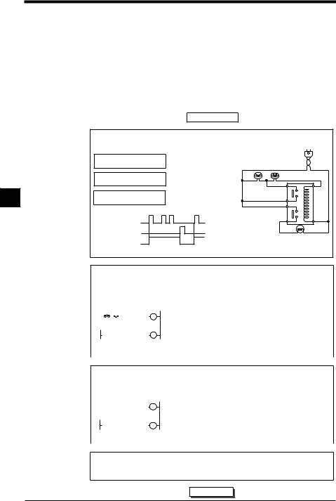
1.1 Before Creating Programs
1.1 Before Creating Programs
This section describes what you should know before creating programs and operations for the Visual KV Series.
1.1.1 Flow from Introduction to Operation
This section describes an overview of program creation procedures, functions used, and setting items.
In the example described below, a latch circuit is created as a program for the Visual KV Series.
Introduction
|
|
|
|
|
|
Examining contents of operations |
|
||
|
Figure 1 shows a latch circuit which operates as follows. |
Fig. 1 |
||
|
|
|
|
|
|
Pushbutton switch PB1: ON |
|
PB1 = N.O. contact switch |
|
|
Pilot lamp (PL) turns on. |
PB2 = N.C. contact switch |
||
|
Pushbutton switch PB2: OFF |
|||
|
PB1 PB2 |
|||
|
|
|
|
|
|
|
Pilot lamp (PL) remains |
|
|
|
Pushbutton switch PB1: OFF |
|
||
|
Pushbutton switch PB2: OFF |
lit even if PB1 turns |
|
|
|
OFF. |
|
||
|
|
|
|
|
1 |
|
|
|
|
Pushbutton switch PB1: OFF |
Pilot lamp (PL) goes out |
|
||
Pushbutton switch PB2: ON |
when PB2 is set to ON. |
|
||
|
Time chart |
|
|
|
|
PB1 contact |
ON |
|
|
|
OFF |
|
|
|
|
|
|
|
|
|
PB2 contact |
ON |
|
|
|
OFF |
|
PL |
|
|
|
|
||
|
|
ON |
|
|
|
|
|
|
|
|
PL OFF |
|
|
|
|
Next, a program is created that will use the same operation as this circuit to control a PLC. |
|||
RL (Relay)
Program examination
Circuit 1 shows relay symbols for the latch circuit.
Examine which contact in the Visual KV Series is used for each pushbutton switch and pilot lamp (Table 1). When many I/O devices are required for control, expansion units should also be considered.
Circuit 1 |
|
|
Table 1 |
|
|
||||||||
|
|
|
|
|
|
|
|
|
|
|
|
|
|
|
|
|
|
|
|
|
|
|
|
RL |
I/O device |
Contact No. |
|
|
|
|
|
|
|
|
|
|
|
||||
|
|
PB1 |
|
PB2 |
|
Relay (coil) |
Pushbutton switch PB1 (N.O. contact) |
Input relay (0000) |
|
||||
|
|
|
RL |
|
|
|
|
||||||
|
|
|
|
Relay (contact) |
|
|
Pushbutton switch PB2 (N.C. contact) |
Input relay (0001) |
|
||||
|
|
|
RL |
|
|
|
|
|
|||||
|
|
|
|
PL |
Relay RL |
Internal relay (1000) |
|
||||||
|
|
|
|
Relay (contact) |
|
|
|||||||
|
|
|
|
|
|
|
|
|
|
|
|
|
|
|
|
|
|
|
|
|
|
|
Pilot lamp |
|
|
|
|
|
|
|
|
|
|
|
|
|
Pilot lamp PL |
Output coil (0500) |
|
||
|
|
|
|
|
|
|
|
|
|
|
|
||
|
|
|
|
|
|
|
|
|
|
|
|
|
|
|
|
|
|
|
|
|
|
|
|
|
|
|
|
|
|
|
|
|
|
|
|
|
|
|
|
|
|
Program creation
Edit a program using the "LADDER BUILDER for KV" programming support software creation tool.
Ladder diagram |
|
Coding list |
|
|||||
|
0000 |
0001* |
1000 |
LD |
0000 |
|
||
|
|
|
|
|
|
OR |
1000 |
|
|
1000 |
|
|
|
AND |
0001 |
|
|
|
|
|
|
|
0500 |
OUT |
1000 |
|
1000 |
|
|
* Enter "N.O. (AND X001)" to 0001 to |
|||||
|
|
|
LD |
1000 |
||||
|
|
|
|
|
|
|||
|
|
|
|
|
|
OUT |
0500 |
use N.C. contact. |
|
|
|
|
|
|
END |
|
|
|
|
|
|
|
|
|
|
|
|
|
|
|
|
|
|
|
|
Transferring and confirming the program
Transfer the created program to the Visual KV Series, perform a test run, and then confirm operations with the actual devices.
Operation 
3-2 |
Chapter 1 Programming |
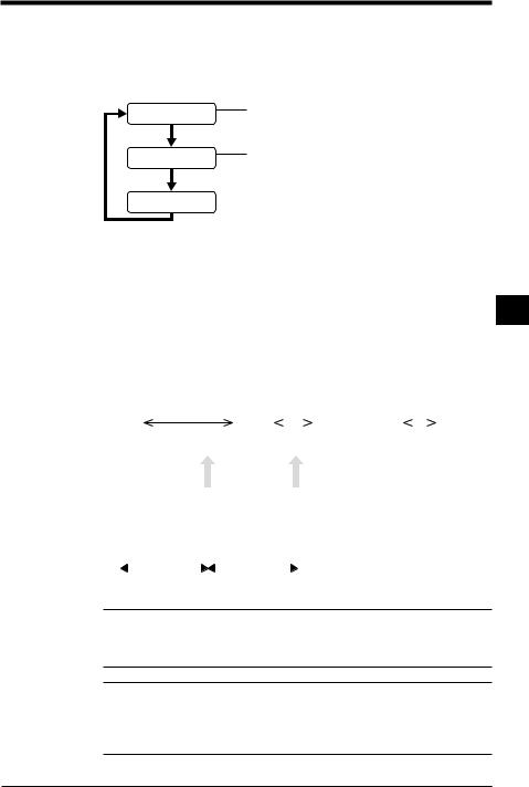
1.1 Before Creating Programs
1.1.2 Scan Time
Scan time
The Visual KV Series repeatedly executes a ladder based on the sequence circuit as follows.
Input processing
Program execution
Writes the ON/OFF status of all input terminals to the input memory before executing the program.
Reads the ON/OFF status of each device (internal utility relay, timer, counter, etc.) based on the instructions, and performs arithmetic operations.
Writes the arithmetic operation result to the output memory.
|
|
Outputs the contents of the output memory to output terminals. |
|
Output processing |
|||
|
|||
The duration of time required to perform one cycle is called the scan time (or cycle time). The scan time varies based on program size and the instructions used in the program.
Input response time delay
In addition to the I/O processing time, there is also an input time delay in the Visual |
1 |
||||||||||||||||||||||||||||
KV Series caused by the scan time. The input time delay is generated because the |
|
||||||||||||||||||||||||||||
|
|||||||||||||||||||||||||||||
input status can only be read during the input processing time. If the input status is |
|
||||||||||||||||||||||||||||
changed after input processing, the changed contents can only be read during the |
|
||||||||||||||||||||||||||||
next scan time. |
|
|
|
|
|
|
|
|
|
|
|
|
|
|
|
|
|
|
|
|
|
|
|
||||||
In the figure below, 1 and 2 can be read but 3 cannot be read. |
|
|
|
|
|
|
|
|
|
|
|||||||||||||||||||
Input signal |
|
1 |
|
|
2 |
|
|
|
|
3 |
|
|
|
|
|
|
|
||||||||||||
|
|
|
|
|
|
|
|
|
|
|
|
|
|
|
|
|
|
|
|
|
|
|
|
||||||
ON |
|
|
|
|
|
|
|
|
|
|
|
|
|
|
|
|
|
|
|
|
|
|
|
|
|
|
|
||
|
|
|
|
|
|
|
|
|
|
|
|
|
|
|
|
|
|
|
|
|
|
|
|
|
|
|
|||
OFF |
|
|
|
|
|
|
|
Read |
|
|
|
|
|
|
|
|
|
|
|
|
|
|
|
|
|
|
|
||
|
|
|
|
|
|
|
|
|
|
|
|
Read |
|
|
|
|
|
|
|
|
|
|
|
|
|||||
|
|
|
|
|
|
|
|
|
|
|
|
|
|
|
|
|
|
|
|
|
|
|
|
|
|
||||
|
|
|
|
|
|
|
|
|
|
|
|
|
|
|
|
|
|
|
|
|
|
|
|
|
|
|
|
|
|
|
processingOutput |
processingInput |
|
|
Program |
|
|
processingOutput |
processingInput |
|
|
Program |
processingOutput |
processingInput |
Program |
processingOutput |
processingInput |
|
Program |
processingOutput |
processingInput |
|
|
|
|||||
|
|
|
|
|
|
|
|
|
|
|
|
|
|
|
|
|
|
|
|
|
|
|
|||||||
|
|
|
|
|
|
execution |
|
|
|
|
|
|
execution |
|
|
execution |
|
|
|
execution |
|
|
|
|
|
|
|||
|
|
|
|
|
|
|
|
|
|
|
|
|
|
|
|
|
|
|
|
|
|
|
|
|
|
|
|
|
|
|
|
|
|
|
|
|
|
|
|
|
|
|
|
|
|
|
|
|
|
|
|
|
|
|
|
|
|
|
|
|
|
|
|
|
|
|
|
|
|
|
|
|
|
|
|
|
|
|
|
|
|
|
|
|
|
|
|
||
|
|
|
|
|
|
Scan time |
|
|
|
|
|
|
Scan time |
|
|
|
|
|
|
|
|
|
|
|
|
|
|
|
|
|
|
|
|
|
|
|
|
|
|
|
|
|
|
|
|
|
|
|
|
|
|
|
|
|
|
||||
|
|
|
|
|
|
|
|
|
|
|
|
|
|
|
|
|
|
|
|
|
|
|
|
|
|
|
|
|
|
|
|
|
|
|
|
|
|
|
|
|
|
|
|
|
|
|
|
|
|
|
|
|
|
|
|
|
|
|
|
Reference: The maximum and minimum values of the input response time are as follows.
Maximum value: Input time constant + Scan time x 2 + Output response delay time
Minimum value: Input time constant + Scan time + Output response delay time
Note 1: When the input time constant is made small by setting the HSP instruction, special utility relay 2813, and data memory DM1940, a signal may not be received if its ON time is shorter than the scan time.
Note 2: The INT instruction is independent of the scan time.
Note 3: The minimum scan time is 140 s (with the basic unit).
Chapter 1 Programming |
3-3 |

1.2 User Memory
1.2 User Memory
This section describes the allowable size (capacity) of a program which can be created in the Visual KV Series.
1.2.1 Program Capacity
When a user program is created for the Visual KV Series, the maximum number of steps a program can contain using the mnemonic diagram varies based on the byte count of the instructions used. The instruction byte count is determined individually for each instruction.
For more about byte counts for each instruction, refer to "2.1 Instruction List" (p.3-34).
Maximum number of lines in a program
In the KV-10xx/16xx, a program with approximately 2,000 steps can be written. In the KV-24xx/40xx, a program with approximately 4,000 steps can be written.
• Total byte count of the memory used by instructions ≤ 6,000 bytes / 12,000 bytes
• Total byte count of the memory used by objects of instructions ≤ 12,000
bytes / 24,000 bytes
1
*In the description above, a value on the left side indicates the byte count for the KV-10xx/16xx, while a value on the right side indicates the byte count for the KV-24xx/40xx.
*The memory occupied by objects indicates the memory required to execute a program when operation is started.
For example, the allowable number of steps to be written can be calculated from the memory occupied by the instructions as follows.
12,000 bytes / 3 bytes (average byte count of an instruction) = 4,000 steps
Note: If either the memory occupied by the instructions or the memory occupied by objects of a program exceeds the specified memory capacity, the program cannot be written or executed.
Calculating the byte count used
The byte count used in this program can be calculated as shown in the table below.
|
0000 |
|
#00020 |
||||||
|
|
|
|
T000 |
|
T000 |
|
||
|
0500 |
0500 |
|
||||||
|
|
||||||||
|
|
|
|
|
|
|
|
|
|
Line No. |
Instruction |
Operand |
Byte count |
Number of objects |
00000 |
LD |
0000 |
3 |
5 |
00001 |
OR |
0500 |
3 |
4 |
00002 |
TMR |
000#00020 |
2 |
7 |
00003 |
ANB |
T000 |
3 |
8 |
00004 |
OUT |
0500 |
3 |
8 |
|
Total |
|
14 bytes |
32 bytes |
|
|
|
|
|
3-4 |
Chapter 1 Programming |

1.3 Device Configuration
1.3 Device Configuration
"Device" is a general name for relays, registers, etc. processed by instructions. This section describes the available devices in the Visual KV Series and their general use.
1.3.1 Device List
Relay list
Relay No. |
Normal use |
High-speed |
High-speed use (2) |
Remarks |
|
|
||
use (1) |
|
|||||||
|
|
|
|
|
|
|
||
0000 |
|
|
|
|
They function as B phase of high-speed |
|
||
|
Input relays |
|
(Polarity inversion |
counters through specification of utility relays in |
|
|||
0001 |
Interrupt inputs |
|||||||
KV-10. |
|
|
||||||
(Direct input |
allowed) |
|
|
|||||
|
INT0 to INT3 |
|
|
|
|
|||
0002 |
allowed area) |
Input captures |
– |
|
|
|||
|
|
|||||||
0003 |
|
|
|
|
– |
|
||
|
|
|
|
|
|
|
|
|
0004 |
|
High-speed |
High-speed |
|
– |
|
|
|
|
counter 0 input |
counter 0 |
A phase |
|
||||
|
|
|
|
|
||||
0005 |
|
High-speed |
High-speed |
input |
– |
|
|
|
|
counter 1 input |
counter 1 |
|
|
||||
|
|
|
|
|
|
|||
|
|
|
|
|
|
|
|
|
0006 |
|
|
High-speed |
|
– |
|
|
|
Input relays |
|
counter 0 |
B phase |
|
1 |
|||
|
|
|
|
|||||
0007 |
|
High-speed |
input |
– |
|
|||
|
|
|
||||||
|
|
counter 1 |
|
|
|
|||
|
|
– |
|
|
|
|
||
|
|
|
|
|
|
|
||
0008 |
|
High-speed |
|
– |
|
|
||
|
|
|
|
|
||||
|
|
counter 0 |
Preset |
|
||||
|
|
|
|
|
|
|||
0009 |
|
|
High-speed |
input |
– |
|
|
|
|
|
counter 1 |
|
|
||||
|
|
|
|
|
|
|
||
0010 to 0415 |
Input relays |
|
|
|
– |
|
||
|
|
|
|
|
|
|
||
0500 |
|
High-speed counter 0 output |
|
70 points |
|
|||
|
|
|
|
|
|
|
|
|
|
Output relays |
High-speed |
Specified frequency |
|
|
|
||
0501 |
counter 1 |
– |
|
|
||||
(Direct output |
pulse output |
|
|
|||||
|
output |
|
|
|
|
|||
|
allowed area) |
|
|
|
|
|
||
|
|
|
|
|
|
|
||
0502 |
Ramp-up/down control output |
|
– |
|
|
|||
|
|
|
||||||
|
|
|
|
|
|
|
||
0503 |
|
|
– |
|
– |
|
||
|
|
|
|
|
|
|
||
0504 to 0915 |
Output relays |
|
|
|
76 points |
|
||
|
|
|
|
|
|
|
||
1000 to 1915 |
Internal utility relays |
|
|
160 points |
|
|||
|
|
|
|
|
|
|
||
2000 to 2815 |
Special utility relays |
|
|
144 points |
|
|||
|
|
|
|
|
|
|
||
2900 to 2915 |
Special utility relays |
|
|
HKEY information storage area |
|
|||
|
|
|
|
|
|
|
||
3000 to 17915 |
Internal utility relays |
|
|
2,144 points |
|
|||
|
|
|
|
|
|
|
|
|
Note 1: The ON/OFF status of the set functions is always cleared when the operation mode is changed from PROGRAM to RUN. However, special utility relays 2700 to 2715 are held even when the operation mode is changed from PROGRAM to RUN or when the power is turned off.
Note 2: Internal utility relays can be held by setting the MEMSW instruction
List of I/O relays in basic units
Model |
KV-10xx |
KV-16xx |
KV-24xx |
KV-40xx |
Basic input relays |
0000 to 0005 |
0000 to 0009 |
0000 to 0015 |
0000 to 0107 |
Basic output relays |
0500 to 0503 |
0500 to 0505 |
0500 to 0507 |
0500 to 0515 |
|
|
|
|
|
Chapter 1 Programming |
3-5 |

|
1.3 Device Configuration |
|
|
|
|
|
|
|
|
|
|
|
List of relays in expansion units |
|
|
|
|
|
|
|
|
|
|
|
■ Input units |
|
|
|
|
|
|
|
|
|
|
|
Connection |
KV-E4X |
|
KV-E8X |
|
KV-E16X |
|
|
|||
|
order |
KV-10/16/24 |
KV-40 |
KV-10/16/24 |
KV-40 |
KV-10/16/24 |
KV-40 |
|
|
||
|
1st input |
00 to 103 |
00 to120 |
|
002to 10 |
0031to 20 |
7002to 11 |
27001to 21 |
5 |
5 |
|
|
module |
|
|||||||||
|
|
|
|
|
|
|
|
|
|
|
|
|
2nd input |
00 to 203 |
00 to230 |
|
003to 20 |
0032to 30 |
7003to 21 |
37002to 31 |
5 |
5 |
|
|
module |
|
|||||||||
|
|
|
|
|
|
|
|
|
|
|
|
|
3rd input |
00 to 303 |
00 to340 |
|
004to 30 |
0033to 40 |
7004to 31 |
47003to 41 |
5 |
5 |
|
|
module |
|
|||||||||
|
|
|
|
|
|
|
|
|
|
|
|
|
4th input |
00 to 403 |
4 |
|
00 to 40 |
4 |
4007 to 41 |
|
5 |
|
|
|
module |
|
|
|
|||||||
|
|
|
|
|
|
|
|
|
|
|
|
|
■ Output units |
|
|
|
|
|
|
|
|
|
|
|
Connection |
KV-E4T(P)/R |
|
KV-E8T(P)/R |
|
KV-E16T(P)/R |
|
|
|||
|
order |
|
|
|
|
||||||
|
|
|
|
|
|
|
|
|
|
|
|
|
1st output |
00 to 603 |
6 |
00 to 60 |
6 |
6007 to 61 |
|
5 |
|||
|
module |
|
|||||||||
|
|
|
|
|
|
|
|
|
|
|
|
|
2nd output |
00 to 703 |
7 |
00 to 70 |
7 |
7007 to 71 |
|
5 |
|||
|
module |
|
|||||||||
|
|
|
|
|
|
|
|
|
|
|
|
1 |
3rd output |
00 to 803 |
8 |
00 to 80 |
8 |
8007 to 81 |
|
5 |
|||
module |
|
||||||||||
|
|
|
|
|
|
|
|
|
|
||
|
|
|
|
|
|
|
|
|
|
|
|
|
4th output |
00 to 903 |
9 |
00 to 90 |
9 |
9007 to 91 |
|
5 |
|||
|
module |
|
|||||||||
|
|
|
|
|
|
|
|
|
|
|
|
|
■ I/O units |
|
|
|
|
|
|
|
|
|
|
|
Connection |
|
|
|
KV-E4XR/T(P) |
|
|
|
|
|
|
|
Input relays |
|
|
|
Output relays |
|
|
||||
|
order |
|
|
|
|
|
|||||
|
KV-10/16/24 |
KV-40 |
KV-10/16/24 |
|
KV-40 |
|
|
||||
|
|
|
|
|
|||||||
|
1st input |
00 to 103 |
1200 to 20 |
|
3 |
|
|
|
|
||
|
module |
|
|
|
|
|
|||||
|
|
|
|
|
|
|
|
|
|
|
|
|
2nd input |
00 to 203 |
2300 to 30 |
|
3 |
|
|
|
|
||
|
module |
|
|
|
|
|
|||||
|
|
|
|
|
|
|
|
|
|
|
|
|
3rd input |
00 to 303 |
3400 to 40 |
|
3 |
|
|
|
|
||
|
module |
|
|
|
|
|
|||||
|
|
|
|
|
|
|
|
|
|
|
|
4th input |
400 to 403 |
|
|
|
module |
|
|
||
|
|
|
||
|
|
|
|
|
1st output |
00 to 603 |
600 to 60 |
3 |
|
module |
||||
|
|
|
||
|
|
|
|
|
2nd output |
00 to 703 |
700 to 70 |
3 |
|
module |
||||
|
|
|
||
3rd output |
00 to 803 |
800 to 80 |
3 |
|
module |
||||
|
|
|
||
4th output |
00 to 903 |
900 to 90 |
3 |
|
module |
||||
|
|
|
*Relay Nos. of expansion units are automatically assigned in the order of connection.
*The connection order is counted only for input and output units. When I/O units are connected, they are counted as input units and output units separately.
3-6 |
Chapter 1 Programming |
Loading...