


 Loading...
96007E
Safety Light Curtain
SL-V Series Version 3.0
User’s Manual
Introduction
This user’s manual describes handling, operation, and precautionary information for the SL-V Series Safety Light Curtain ("SL-V").
Read this user’s manual thoroughly before operating the SL-V in order to understand the device features, and keep this user’s manual readily available for reference. Ensure that the end user of this product receives this manual.
In this user’s manual, "SL-VF" represents the finger protection type with the detection capability of 14 mm, "SL-VH" represents the hand protection type with the detection capability of 25 mm, "SL-VL" represents the body protection type with the detection capability of 45 mm, "SL-VFM" represents the finger protection and rigid enclosure type with the detection capability of 14 mm, "SL-VHM" represents the hand protection and rigid enclosure type with the detection capability of 25 mm, "SL-VLM" represents the body protection and rigid enclosure type with the detection capability of 45 mm, and "SL-V" represents all the models including the SL-VF, SL-VH, SL-VL, SL-VFM, SL-VHM, and SL-VLM.
 See "Model" (page 7-2).
Safety headings
This user’s manual uses the following headings to display important safety information. Strict adherence to the instructions next to these heading is required at all times.
Danger |
Failure to follow the instruction results in significant harm to the machine operators including |
|
serious injury or death. |
|
|
|
|
|
|
|
|
 Caution Failure to follow the instruction may result in damage to the SL-V or to the machine on which it is installed.
NOTE |
Provides additional information for proper operation. |
|
Reference |
Provides advanced and useful information for operation. |
|
Indicates reference pages in this or another manual.

Safety Precautions
General precautions
•You must verify that the SL-V is operating correctly in terms of functionality and performance before the start of machine and the operation of the SL-V.
•KEYENCE does not guarantee the function or performance of the SL-V if it is used in a manner that differs from the SL-V specifications contained in this user’s manual or if the SL-V is modified by the customer.
•When using the SL-V to protect machine operators against a hazard or hazardous zone or using the SL-V as a safety component for any purpose, always follow the applicable requirements of the laws, rules, regulations and standards in the country or region where the SL-V is used. For such regulations, you should contact directly to the regulatory agency responsible for occupational safety and health in your country or region.
•Depending on the type of machine on which the SL-V is to be installed, there may be special safety regulations related to the use, installation, maintenance, and operation of the safety component. In such a case, you must fulfill such safety regulation. The responsible personnel must install the SL-V in strict compliance with such safety regulations.
•The responsible personnel must do the training to the assigned personnel for the correct use, installation, maintenance, and operation of the SL-V. "Machine operators" refers to personnel who have received appropriate training from the responsible personnel and are qualified to operate the machine correctly.
•Machine operators must have specialized training for the SL-V, and they must understand and fulfill the safety regulations in the country or region in which they are using the SL-V.
•When the SL-V fails to operate, machine operators must immediately stop the use of the machine and the SL-V and report this fact to the responsible personnel.
•The SL-V is designed with the assumption that it would be correctly installed in accordance with the installation procedures described in this user’s manual and correctly operated according to the instructions in this user’s manual. You must perform an appropriate installation of the SL-V after performing a sufficient risk assessment for the target machine.
•The SL-V should be processed as an industrial waste product when being disposed.
SL-V-M-NO0-E |
96007E |
1 |

Precaution on use
Operators
 Danger
•In order to operate the SL-V correctly, the responsible personnel and machine operators must fulfill all of the procedures described in this user’s manual.
•No person other than the responsible personnel and machine operators should be allowed to install or test the SL-V.
•When performing electrical wiring, always fulfill the electrical standards and regulations for the country or region in which the SL-V is used.
Environment of use
Danger |
• Do not use the SL-V in an environment (temperature, humidity, interfering light, etc.) that |
|
|
|
does not conform to the specifications contained in this user’s manual. |
•Be sure to confirm that the SL-V keeps normal operation when electromagnetic radiation is generated by wireless devices. (If you use wireless devices such as cellular phones or transceivers in the vicinity of the SL-V.)
•The SL-V is not designed to be explosion-proof. Never use it in the presence of flammable or explosive gases or elements.
•Be sure to confirm no deterioration in product quality if you use the SL-V in the presence of substances, such as heavy smoke, particulate matter, or corrosive chemical agents.
•Do not install the SL-V in areas where the SL-V is exposed to intense interference light such as direct sunlight, and direct or indirect light from inverter-type fluorescent lamp (rapid-start type lamp, high-frequency operation type lamp, etc).
•Be sure to absolutely confirm that there is nobody in the hazardous zone, before the interlock is released (i.e. the machine system restarts) by the interlock reset mechanism. Failure to follow this warning results in a significant harm to the machine operators, including serious injury or death.
•Be sure to absolutely confirm that there is nobody in the hazardous zone, before the override function is activated. Failure to follow this warning results in a significant harm to the machine operators, including serious injury or death.
Target machine
 Danger
•The SL-V has not undergone the model certification examination in accordance with Article 44-2 of the Japanese Industrial Safety and Health Law. The SL-V, therefore, cannot be used in Japan as a “Safety Device for Press and Shearing machines” as established in Article 42 of that law.
•The machine on which the SL-V is to be installed must be susceptible to an emergency stop at all operating points during its operation cycle. Do not use the SL-V for machines with irregular stop times.
•Do not use the SL-V for power presses equipped with full-revolution clutches.
•The SL-V cannot be used as a PSDI because it does not fulfill the requirements of OSHA 1910.217(h). Refer to OSHA 1910.217 for the PSDI mode.
•Do not use the SL-V to control (stop forward motion, etc.) trains, cars and other transportation vehicles, aircraft, equipment for use in space, medical devices, or nuclear power generation systems.
•The SL-V is designed to protect the people or objects from going into/approaching detection zone against machine’s hazard or hazardous zone. It cannot provide protection against objects or materials that are expelled from the machine’s hazard or hazardous zone, so you must establish additional safety measures such as installing safeguards when there is the possibility of such projectiles.
2 |
SL-V-M-NO0-E |

Installation
 Danger
•The SL-V must be installed only after ensuring the minimum safety distance between the SL-V and the hazardous zone or hazard as established by the applicable regulations in the country or region in which the SL-V is used. (e.g.EN ISO13855(ISO 13855)in EU countries)
•Choose locations for the installation of the SL-V transmitters and receivers so that they are not subject to the effects of light reflected from glossy surfaces in the area.
•Correct operation and detection is not possible if the receiver has a different number of beam axes from that of the transmitter. You must verify that the number of beam axes is the same between the transmitter and the receiver when installing the SL-V.
•Correct operation and detection is not possible if the receiver has a different beam axis spacing (detection capability) from that of the transmitter. You must verify that the beam axis spacing (detection capability) is the same between the transmitter and the receiver when installing the SL-V.
•The SL-V must be installed so that the machine operator is able to go into or approach the hazardous zone or hazards only by passing through the detection zone of the SL-V. Strictly avoid installation that allows the machine operator or a part of the machine operator's body to go into or approach the hazardous zone or hazards without passing through the detection zone of the SL-V or to remain in a position between the detection zone of the SL-V and the hazardous zone or hazard. In case where you install the SL-V units in series (series connection), you always must check the installation carefully whether you follow this warning, especially after installation and maintenance.
Even if you forget to install the SL-V unit to be connected in series, or if the series connection cable is disconnected, the SL-V does not detect such a missing or disconnection. (It means the SL-V starts the normal operation.) This causes a dangerous situation because there is no protection at the area to be protected.
•You must always perform the pre-check tests after installing the SL-V in accordance with the pre-check test procedures, such as items specified in this user’s manual, in order to verify that the test pieces can be detected in all of the detection zones.
•Interlock reset mechanisms (such as switches) must be installed so that the whole hazardous zone can be checked by the responsible personnel. Interlock reset mechanisms should not be accessible from within the hazardous zone.
•Muting is a function to allow a temporary automatic suspension of the SL-V safety functions while the SL-V is receiving a signal from muting devices (such as sensors or switches). Therefore, additional safety measures are required for the machine on which the SL-V is installed in order to ensure safety while the muting is activated.
•Muting devices, the installation of those devices and the procedure to activate the muting function must fulfill the conditions specified in this user’s manual and the requirements of the laws, rules, regulations and standards in the country or region in which the SL-V and those devices are used. Failure to follow this warning may result in significant harm to the machine operators, including serious injury or death.
•When you install muting devices (such as sensors or switches) for muting, the following conditions must be fulfilled.
(1)Muting devices must be installed so that the muting cannot be activated if the hazardous zone of the machine is in an unsafe condition or cycle.
(2)Muting devices must be installed so that the muting cannot be activated even if the personnel is accidentally approaching the detection zone of the SL-V.
•The muting device must be installed such that only responsible personnel have access to that device to change its installation or orientation. Special tools must be required to ensure that only responsible personnel are capable of installation, orientation or change of muting device.
•Only the responsible personnel may be allowed to install or wire the devices to activate the muting function.
SL-V-M-NO0-E |
3 |

•The installation of muting lamp may be required by the laws, rules, regulations, and standards in the country or region in which the SL-V is used if you apply the muting function. It depends on the machine application and/or the result of your risk assessment. If it is necessary for you to provide the muting lamp, you must fulfill the requirements because you are fully responsible for installation of muting lamp.
•When the reduced resolution function is applied, the detection capability varies according to your configuration. Make sure to accurately calculate the safety distance according to the detection capability, and install the SL-V at a distance greater than or equal to the minimum safety distance away from the hazardous zone or hazard. The installation of additional safety measures, such as a safeguarding, may be required if the detection capability varies due to the configuration of the reduced resolution function. On your own responsibility, you must perform the risk assessment based on your configuration of the reduced resolution function in order to reduce the risk.
•When the fixed blanking function is applied, a hazardous clearance that is not protected by the SL-V may be generated between the obstacle and the SL-V. You must install an additional safety measure such as a safeguard for this clearance.
•The override is a function to allow a temporary manual suspension of the safety functions of the SL-V. Therefore, additional safety measures are required for the whole machine system on which the SL-V is installed in order to ensure safety while the override is activated.
•The override devices, the installation of those devices and the procedures to activate the override must fulfill the conditions specified in this manual as well as the requirements of the laws, rules, regulations and standards in the country or region in which the SL-V and those devices are used. Failure to follow this warning may result in significant harm to the machine operators, including serious injury or death.
•The override devices, which are used for activation of override, must be manual operating device. When installing the devices to activate the override, those devices must be installed so that the whole hazardous zone can be checked by the responsible personnel and so that it is not possible for machine operators to operate those devices in the hazardous zone.
•The installation of the indication for override may be required by the laws, rules, regulations, and standards in the country or region in which the SL-V is used if you apply the override function. It depends on the machine application and/or the result of your risk assessment. If it is necessary for you to provide the indication for override, you must fulfill the requirements because you are fully responsible for installation of the indication for override.
•The customer is fully responsible for complying with the requirements for the muting and/or override. Those who use muting and/or override must fulfill all of the requirements related to muting and/or override. KEYENCE accepts NO responsibility or NO liability for any damage or any injury due to the unauthorized installation, usage or maintenance, which are not specified in this user’s manual, and/or due to noncompliance with the laws, rules, regulations and standards in the country or region in which the SL-V is used.
•Securely tighten mounting brackets and cable connectors used for the installation of the SL- V in accordance with the torque values specified in this user’s manual.
Circuit design and wiring
 Danger • Always turn off the power to the SL-V when performing electrical wiring.
•You must fulfill the electrical standards and regulations in the country or region in which the SL-V is being used when you perform the electrical wiring.
•To avoid the risk of electric shock, do not connect any of the SL-V inputs to DC power sources outside of the range of 24 V DC + 10% or to any AC power source.
•To avoid the risk of electric shock, be sure that the hazardous voltage is isolated from all wiring of the SL-V with reinforced insulation or double insulation.
4 |
SL-V-M-NO0-E |

•In order to fulfill the requirements in IEC61496-1, UL61496-1, EN61496-1 and UL508, power supply for the SL-V must fulfill the conditions listed below.
(a)A rated output voltage of 24 V DC (SELV, Overvoltage Category II) within +10% and -20%.
(b)Double insulation or reinforced insulation between the primary and secondary circuits.
(c)Output holding time of 20 ms or more.
(d)A power supply must fulfill the requirements of the electrical safety and electromagnetic compatibility (EMC) regulations or standards in all countries and/or regions where the SL-V is used.
(e)A secondary circuit of power supply (output) must fulfill the requirements for Class 2 Circuits or Limited Voltage/Current Circuits specified in UL508, if the SL-V is used in the United States or Canada.
•Do not install the electric wiring of the SL-V together with or in parallel with high-voltage electrical or power lines.
•Both OSSD outputs provided on the SL-V must be used to establish a safety-related machine control system. Establishing a safety-related machine control system with just one of the OSSD outputs cannot stop the machine due to an OSSD output malfunction and may result in significant harm to the machine operators, including serious injury or death.
•When using a PNP output type cable, do not cause short-circuit between the OSSD and +24V. Otherwise, the OSSDs keep staying at the ON-state and it causes a dangerous situation.
•When using a PNP output type cable, be sure to connect the load between the OSSD and 0V to avoid a dangerous situation. If the load is incorrectly connected between the OSSD and +24V, the logic of the OSSD operation will be reversed and the OSSD will change to an ON state when the SL-V detects the interruption in the detection zone. This is a dangerous situation.
•When using NPN output type cables, do not cause short-circuit between the OSSD and 0V. Otherwise, the OSSDs keep staying at the ON-state and it causes a dangerous situation.
•When using an NPN output type cable, be sure to connect the load between the OSSD and +24V to avoid a dangerous situation. If the load is incorrectly connected between the OSSD and 0V, the logic of the OSSD operation will be reversed and the OSSD will change to an ON state when the SL-V detects the interruption in the detection zone. This is a dangerous situation.
•In case of wiring, regardless of PNP or NPN output type cables, you must fulfill the requirements of Clause 9.4.3 in IEC60204-1: 2005 in order for the protection against maloperation due to earth fault.
•The Alert output, AUX output, Clear/Blocked Output, state information output and interlock- reset-ready output are not allowed to be used as safety outputs for safety-related machine control systems. Usage of these functions as safety outputs may result in a significant harm to the machine operators, including serious injury or death.
•The wait input is not allowed to be connected to the output from any components comprising a part of the safety-related machine control system. If the wait input is connected to the output of a safety component it may result in a significant harm to the machine operators, including serious injury or death.
•The transmitter and receiver cables must be within the lengths specified in this user’s manual. Usage of cables longer than the specified length may cause the improper operation of safety functions and may cause a dangerous situation.
Testing and maintenance
•You must always perform the pre-check test in accordance with the pre-check test procedures, after maintenance, adjustment or alignment of the target machine or the SL-V and before the machine startup.
•If the SL-V does not operate properly when you perform pre-check test in accordance with the precheck test procedures specified in this user’s manual, do not operate the machine.
•You must periodically examine the machine to verify that all brakes, other stop mechanisms, and control devices operate reliably and correctly in addition to checking the SL-V.
•The responsible personnel must perform maintenance procedures as specified in this user’s manual to ensure safety to the machine and SL-V.
SL-V-M-NO0-E |
5 |

Standards and regulations
1The SL-V is a "Safety Part" specified in the EU Machinery Directive (2006/42/EC) Annex V.
The SL-V complies with the following EU Directives and EN Standards and has been certified by TÜV SÜD Product Service GmbH.
EU Directives
•Machinery Directive (2006/42/EC)
•EMC Directive (2004/108/EC)
EN Standards |
|
• EN61496-1 |
Type 4 ESPE |
• EN61496-2 |
Type 4 AOPD |
• EN55011 |
ClassA |
• EN50178 |
|
• EN61508, Part 1 to 4 |
SIL3 |
• EN62061 |
SIL3 |
• EN ISO13849-1 |
Category 4, PLe |
2 The SL-V complies with the following UL (Underwriters Laboratories Inc.) and IEC standards and has been certified by UL. (CCN :NIPF/NIPF7)
• UL61496-1 |
Type 4 ESPE |
• UL61496-2 |
Type 4 AOPD |
• UL508 |
|
• UL1998 |
|
The SL-V also complies with the following regulations.
• FCC Part 15B |
Class A Digital Device |
• ICES-003 |
Class A Digital Apparatus |
3The SL-V has not obtained the model certification examination in accordance with Article 44-2 of the Japanese Industrial Safety and Health Law. Therefore, the SL-V cannot be used in Japan as a "Safety
Devices for Presses and Shearing Machines" as established in Article 42 of that law.
4The SL-V has been designed in consideration of the following standards and regulations. For details regarding the following standards, contact the third-party certification organization, such as UL or TÜV.
Corresponding standards
•EN60204-1
•EN692
•EN693
•OSHA 29 CFR 1910.212
•OSHA 29 CFR 1910.217
•ANSI B11.1 - B.11.19
•ANSI/RIA R15.06 - 1999
•SEMI S2
•"Guidelines for Comprehensive Safety Standards of Machinery", July 31, 2007, number 0731001 issued by Ministry of Health, Labor, and Welfare in Japan.
6 |
SL-V-M-NO0-E |

Table of Contents
Introduction
Safety headings
Safety Precautions .................................................................................................................. |
1 |
General precautions................................................................................................................ |
1 |
Precaution on use ................................................................................................................... |
2 |
Testing and maintenance........................................................................................................ |
5 |
Standards and regulations...................................................................................................... |
6 |
Table of Contents .................................................................................................................... |
7 |
Chapter 1 |
Before Use |
|
|
|
|
1-1 |
Checking the Package Contents ................................................................................ |
1-2 |
|
Standard set......................................................................................................................... |
1-2 |
1-2 |
Options ....................................................................................................................... |
1-3 |
|
Mounting brackets (For SL-VF/VH/VL) ................................................................................. |
1-3 |
|
Mounting brackets (For SL-VFM/VHM/VLM) ........................................................................ |
1-3 |
|
Cables .................................................................................................................................. |
1-4 |
|
Protection bar....................................................................................................................... |
1-7 |
|
Front protection cover and dimmer filter .............................................................................. |
1-8 |
|
SL-V Configurator (SL-VH1S) ............................................................................................... |
1-8 |
1-3 |
Part Description........................................................................................................ |
1-10 |
|
SL-V main unit .................................................................................................................... |
1-10 |
|
With options installed ......................................................................................................... |
1-10 |
|
|
|
Chapter 2 Functions and Features |
|
|
|
|
|
2-1 |
Cable Selection and Function .................................................................................... |
2-2 |
|
Functions.............................................................................................................................. |
2-2 |
|
Cable color and pin assignment .......................................................................................... |
2-3 |
2-2 |
Self-diagnosis Function .............................................................................................. |
2-4 |
|
Lockout condition................................................................................................................. |
2-4 |
|
OSSD.................................................................................................................................... |
2-5 |
2-3 |
Series Connection ...................................................................................................... |
2-6 |
2-4 |
Interlock Function ....................................................................................................... |
2-7 |
|
Automatic start / Automatic reset mode............................................................................... |
2-8 |
|
Other than Automatic start / Automatic reset mode........................................................... |
2-10 |
2-5 |
AUX (Auxiliary) Output ............................................................................................. |
2-14 |
2-6 |
External Device Monitoring (EDM Function) ............................................................ |
2-15 |
2-7 |
Wait Input Function................................................................................................... |
2-16 |
2-8 |
State Information Output .......................................................................................... |
2-18 |
2-9 |
Alert Output .............................................................................................................. |
2-25 |
2-10 |
Clear/Blocked Output ............................................................................................... |
2-27 |
SL-V-M-NO0-E |
7 |

2-11 |
Temporary Suspension of Safety Function............................................................... |
2-29 |
|
Muting function................................................................................................................... |
2-29 |
|
Changing configuration of the muting function.................................................................. |
2-33 |
|
Override function................................................................................................................ |
2-45 |
|
Override Function Settings................................................................................................. |
2-47 |
2-12 |
Fixed Blanking .......................................................................................................... |
2-48 |
2-13 |
Reduced Resolution ................................................................................................. |
2-49 |
2-14 |
I/O Monitoring Function ............................................................................................ |
2-50 |
Chapter 3 Installation to a Machine
3-1 |
Correct Installation Method ........................................................................................ |
3-2 |
|
Transmitter and receiver orientation ..................................................................................... |
3-2 |
|
Mounting position................................................................................................................. |
3-3 |
3-2 |
Safety Distances......................................................................................................... |
3-4 |
3-3 Light Interference Prevention Method......................................................................... |
3-8 |
|
|
Light Interference Prevention Function ................................................................................ |
3-8 |
|
Series Connection ................................................................................................................ |
3-8 |
|
Interference due to installation............................................................................................. |
3-8 |
3-4 Installation Distance from Glossy Surfaces .............................................................. |
3-10 |
|
|
Installation distance not affected by glossy surface.......................................................... |
3-10 |
3-5 |
Cable Connections ................................................................................................... |
3-11 |
|
Cable specification ............................................................................................................ |
3-11 |
|
Unit connection cable ........................................................................................................ |
3-13 |
|
Series connection cable..................................................................................................... |
3-14 |
3-6 Assembling the Mounting Brackets (SL-VF/VH/VL) ................................................. |
3-15 |
|
|
Standard mounting bracket A (OP-42347), B (OP-42348), C (OP-42349), |
|
|
J (OP-83180) ...................................................................................................................... |
3-15 |
|
Thin type mounting bracket (OP-51698)............................................................................ |
3-16 |
|
L-shaped mounting bracket (OP-42371) ........................................................................... |
3-16 |
|
Compact E-to-E mounting bracket (OP-83181) ................................................................. |
3-17 |
|
E-to-E mounting bracket (OP-42370)................................................................................. |
3-17 |
|
Protection bar..................................................................................................................... |
3-18 |
3-7 Assembling the Mounting Brackets (SL-VFM/VHM/VLM) ........................................ |
3-20 |
|
|
Standard mounting bracket (OP-84259) ............................................................................ |
3-20 |
|
Space-saving bracket (OP-84260) .................................................................................... |
3-21 |
3-8 System Configuration for the Muting Function ......................................................... |
3-22 |
|
|
Example: Muting function with 2 muting devices (Sensors) .............................................. |
3-22 |
|
Example: Muting function with 4 of muting devices........................................................... |
3-25 |
|
Example: Muting function with 2 muting devices (Switches)............................................. |
3-29 |
Chapter 4 |
Wiring |
|
|
|
|
4-1 |
Cautions on Wiring and Power Supply ....................................................................... |
4-2 |
8 |
SL-V-M-NO0-E |
|
Power supply........................................................................................................................ |
4-2 |
4-2 |
I/O Circuit Diagram ..................................................................................................... |
4-3 |
4-3 |
Cable Color and Pin Position...................................................................................... |
4-4 |
4-4 |
Examples of Wiring .................................................................................................... |
4-5 |
Chapter 5 |
Optical Alignment |
|
|
|
|
5-1 |
Optical Alignment ....................................................................................................... |
5-2 |
|
Check before optical alignment ........................................................................................... |
5-2 |
|
Alignment procedure............................................................................................................ |
5-2 |
Chapter 6 |
Indicators |
|
|
|
|
6-1 |
Bar LED Indicator ....................................................................................................... |
6-2 |
|
Upon power-up .................................................................................................................... |
6-2 |
|
During normal operation ...................................................................................................... |
6-3 |
6-2 |
Function Indicators ..................................................................................................... |
6-5 |
6-3 |
Center Indicator.......................................................................................................... |
6-6 |
|
Overview .............................................................................................................................. |
6-6 |
|
Changing the Indication Method for the Center indicator.................................................... |
6-7 |
Chapter 7 |
Specifications and Dimensions |
|
|
|
|
7-1 |
Model.......................................................................................................................... |
7-2 |
|
Detection capability of 14 mm (0.55") Optical Axis pitch: "SL-VF" ....................................... |
7-2 |
|
Detection capability of 14 mm (0.55") Optical Axis pitch: "SL-VFM" .................................... |
7-3 |
|
Detection capability of 25 mm (0.98") Optical Axis pitch: "SL-VH" ...................................... |
7-3 |
|
Detection capability of 25 mm (0.98") Optical Axis pitch: "SL-VHM" ................................... |
7-4 |
|
Detection capability of 45 mm (1.77") Optical Axis pitch: "SL-VL" ....................................... |
7-4 |
|
Detection capability of 45 mm (1.77") Optical Axis pitch: "SL-VLM" .................................... |
7-5 |
7-2 |
Specifications ............................................................................................................. |
7-6 |
7-3 Response Time and Current Consumption ................................................................ |
7-7 |
|
|
Response time (OSSD) ........................................................................................................ |
7-7 |
|
Current consumption............................................................................................................ |
7-8 |
7-4 |
Dimensions (SL-VF/VH/VL)........................................................................................ |
7-9 |
|
SL-VF/VH/VL unit .................................................................................................................. |
7-9 |
|
When using the standard mounting bracket, thin bracket, and L-shaped bracket ........... |
7-10 |
|
When mounting only with the E-to-E bracket or the compact E-to-E bracket.................... |
7-12 |
|
Standard mounting bracket J (OP-83180) ......................................................................... |
7-14 |
|
Standard mounting bracket A (OP-42347)......................................................................... |
7-14 |
|
Standard mounting bracket B (OP-42348)......................................................................... |
7-15 |
|
Standard mounting bracket C (OP-42349) ........................................................................ |
7-15 |
|
Thin mounting bracket (OP-51698).................................................................................... |
7-16 |
|
L-shaped mounting bracket (OP-42371) ........................................................................... |
7-16 |
SL-V-M-NO0-E |
9 |

Compact E-to-E mounting bracket (OP-83181) |
.................................................................7-17 |
E-to-E mounting bracket (OP-42370)................................................................................. |
7-17 |
Protection bar..................................................................................................................... |
7-18 |
7-5 Dimensions (SL-VFM/VHM/VLM)............................................................................. |
7-19 |
Standard mounting bracket (OP-84259) ............................................................................ |
7-19 |
Space-saving bracket (OP-84260)................................................................................ |
7-21 |
Appendix
A-1 |
Troubleshooting.......................................................................................................... |
A-2 |
|
If the device is in the lockout condition............................................................................... |
A-2 |
|
If the SL-V is not in the lockout condition ............................................................................ |
A-7 |
A-2 |
Checklist..................................................................................................................... |
A-8 |
|
Checklist before operation .................................................................................................. |
A-8 |
10 |
SL-V-M-NO0-E |

1
Before Use
1-1 Checking the Package Contents . . . . . . . . . . . . . . . . . . . . . . . 1-2
1-2 Options . . . . . . . . . . . . . . . . . . . . . . . . . . . . . . . . . . . . . . . . . . 1-3
1-3 Part Description . . . . . . . . . . . . . . . . . . . . . . . . . . . . . . . . . . . 1-10
SL-V-M-NO1-E |
1-1 |
1
Use Before
1-1 Checking the Package Contents
Standard set
•SL-V transmitter
•SL-V receiver
LEVEL |
5
4
3
2
|
|
1 |
|
|
|
-SL |
|
WAIT |
|
|
|
V08H |
|
FUNCTION |
|
|
|
ø25 |
|
|
OSSD |
|
|
.(0 |
|
|
INTER |
|
|
|
|
LOCK |
|
|
|
98") |
|
|
|
|
|
|
|
|
|
|
|
|
|
|
|
|
|
|
|
|
|
|
|
|
|
|
|
|
|
x1 |
|
• |
Test piece x1 |
|
x1 |
|
|
(Test piece with diameter of 25 mm and length of 200 mm for SL-VH, |
|
|
|
|
SL-VHM, and test piece with diameter of 14mm and length of |
|
|
|
|
200mm for SL-VF, VFM) |
|
LEVEL |
|
|
* The test piece (diameter: 45 mm) for the |
|
5 |
|
|
||
4 |
|
|
||
3 |
|
|
SL-VL, VLM is not supplied. Please pre- |
|
2 |
|
|
||
1 |
|
|
pare by yourself. |
|
MUTE1 |
SL |
|
||
- |
|
|
||
MUTE2 |
V08H |
|
|
|
OSSD |
ø25 |
|
|
|
INTER |
|
|
||
.(0 |
• |
Ferrite core x1 (SL-VF, VH, VL, VLM only) |
||
LOCK |
||||
|
98") |
|||
|
|
|||
|
|
|
x 2 (SL-VFM only) |
• User’s manual x1
1-2 |
SL-V-M-NO1-E |
1-2 Options
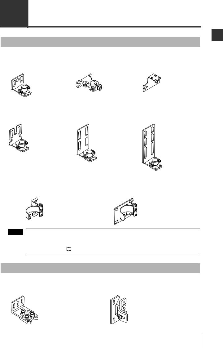
Mounting brackets (For SL-VF/VH/VL)
 See "Assembling the Mounting Brackets (SL-VF/VH/VL)" (page 3-15).
Standard mounting |
Thin type mounting |
L-shaped mounting |
bracket J (OP-83180) |
bracket (OP-51698) |
bracket (OP-42371) |
Materials: SUS304 |
Materials: SUS304 |
Materials: SUS304 |
|
x2 |
x2 |
x2 |
|
|
M3 (Length: 7 mm) screw x6 |
M3 (Length: 7 mm) screw x6 |
M3 miniature flathead (Length: 5 mm) |
(For mounting to the unit) |
(For mounting to the unit) |
screw x6 (For mounting to the unit) |
Standard mounting |
Standard mounting |
Standard mounting |
bracket A (OP-42347) |
bracket B (OP-42348) |
bracket C (OP-42349) |
Materials: SUS304 |
Materials: SUS304 |
Materials: SUS304 |
x2
M3 (Length: 7 mm) screw x10 |
x2 |
|
|
(For mounting to the unit) |
|
|
|
M3 (Length: 7 mm) screw x10 |
x2 |
||
(For mounting to the unit) |
|
||
|
|
||
|
|
|
M3 (Length: 7 mm) screw x10 |
|
|
|
(For mounting to the unit) |
Compact E-to-E mounting bracket (OP-83181) |
E-to-E mounting bracket (OP-42370) |
||
Materials: SUS304 |
|
Materials: SUS304 |
|
|
x2 |
x2 |
|
|
|
NOTE |
If the length for a single SL-V unit is 710 mm or greater, use a compact E-to-E mounting bracket or an E- |
|
|
to-E mounting bracket additionally as an intermediate support bracket. |
|
|
For more information about the required number of intermediate support brackets and the limits on the |
|
|
mounting position, see |
"Dimensions (SL-VF/VH/VL)" (page 7-9). |
Mounting brackets (For SL-VFM/VHM/VLM)
 See "Assembling the Mounting Brackets (SL-VFM/VHM/VLM)" (page 3-20).
Standard mounting bracket (OP-84259) |
Space-saving bracket (OP-84260) |
|||
Material: SPHC |
|
Material: SPHC |
|
|
|
|
|
Hexagon socket bolt |
|
|
Hexagon socket bolt |
|
(M5, length: 6 mm, width across |
|
|
(M5, length: 6 mm, width |
|
flats: 3 mm) x 4 |
|
x2 |
across flats: 3 mm) x 8 |
x2 |
Nut x 4 |
|
(For mounting to the unit) |
(For mounting to the unit) |
|||
|
|
|||
1
Use Before
SL-V-M-NO1-E |
1-3 |
1
Use Before
1-2 Options
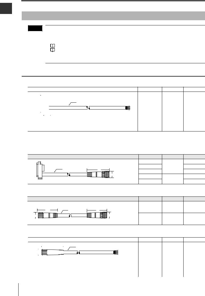
Cables |
|
NOTE |
• There are two types of cable: simple function type and multi-function type. The type of cable used deter- |
|
mines the function that can be used. (The number of conductors is different from each other.) There- |
|
fore, the two types of cables cannot be mixed at the same time. Make sure to use the appropriate type |
|
of cable for your applications. |
|
See "Functions and Features" (page 2-1). |
|
See "Cable Connections" (page 3-11). |
•Cables with different output types cannot be combined. Be sure to match the PNP or NPN output type especially when using the unit connection cable (for extension).
Simple function type
Unit connection cable
Shape |
Model |
Output type |
Length |
|
|
|
|
|
|
|
|
(Transmitter/receiver set) SL-VP7P |
PNP |
7 m |
|||
|
|
|
|
|
|
|
|
φ 5.8 |
|
|
|||
|
|
||||||||||||
36.1 |
|
|
|
|
|
|
|
|
SL-VP15P |
|
15 m |
||
|
|
|
|
|
|
|
|
|
|
|
|
||
|
|
|
|
|
|
|
|
|
|
|
SL-VP7N |
|
7 m |
14.3 |
|
|
|
|
|||||||||
|
|
|
|
|
|
||||||||
8-wire shielded cable |
|
NPN |
|
||||||||||
|
|
||||||||||||
Brown and blue: AWG24 (nominal cross-sectional area of 0.22 mm2) |
SL-VP15N |
|
15 m |
||||||||||
Others: AWG26 (nominal cross-sectional area of 0.14 mm2) |
|
||||||||||||
|
|
|
|||||||||||
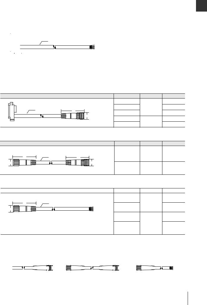
Unit connection cable (for extension use)
Used together with the junction cable or extension cable.
 For more information about cable length standards, see "Cable length specification" (page 1-6).
Shape |
Model |
Output type |
Length |
|
(Transmitter/receiver set) |
SL-VPC03P |
|
0.3 m |
|
SL-VPC5P |
PNP |
5 m |
||
φ 5.8 |
||||
47 |
SL-VPC10P |
|
10 m |
|
|
|
|||
φ14 |
SL-VPC03N |
|
0.3 m |
|
|
NPN |
|||
M12 connector, male |
SL-VPC5N |
5 m |
||
|
Junction cable
|
Shape |
|
Model |
Output type |
Length |
|
|
|
(Transmitter/receiver set) |
SL-VCC10P |
PNP |
10 m |
|
|
φ 5.8 |
|
||||
41.5 |
47 |
|
|
|
||
|
|
|
|
|||
φ 14 |
|
φ14 |
SL-VCC10N |
NPN |
10 m |
|
M12 connector, female |
M12 connector, male |
|||||
|
|
|
||||
Extension cable
Shape |
Model |
Output type |
Length |
|
|
|
|
|
|
41.5 |
|
|
|
|
|
|
|
φ 5.8 |
(Transmitter/receiver set) |
SL-VC5P |
PNP |
5 m |
|||
|
|
|
|
|
|
|
|
|
|
|
|
|
|
||||||||
|
|
|
|
|
|
|
|
|
|
|
|
|
|
|
|
|
|
|
|
|
|
|
|
φ14 |
|
|
|
|
|
|
|
|
|
|
|
SL-VC10P |
|
10 m |
|||||
|
|
|
|
|
|
|
|
|
|
|
|
|
|
|
|
|
|
|
|
||
|
|
M12 connector, female |
|
|
|
|
|
|
|||||||||||||
|
|
|
|
|
|
||||||||||||||||
|
8-wire shielded cable |
|
|
|
|
SL-VC5N |
|
5 m |
|||||||||||||
|
Brown and blue: AWG24 (nominal cross-sectional area of 0.22 mm2) |
|
|
|
|||||||||||||||||
|
Others: AWG26 (nominal cross-sectional area of 0.14 mm2) |
|
NPN |
||||||||||||||||||
|
SL-VC10N |
|
10 m |
||||||||||||||||||
|
|
|
|
|
|
|
|
|
|
|
|
|
|
|
|
|
|
|
|
||
1-4 |
|
|
|
|
|
|
|
|
|
|
|
|
|
|
|
|
|
|
|
|
|
|
|
|
|
|
|
|
|
|
|
|
|
|
|
|
|
|
|
|
|
SL-V-M-NO1-E |
|
|
|
|
|
|
|
|
|
|
|
|
|
|
|
|
1-2 Options |
|
|
|
|
|
|
|
|
|
|
|
|
|
|
|
|
Multi-function type |
|
|
|
||||||||||||
|
|
|
|
|
|
|
|
|
|
|
|
|
|
|
|
Unit connection cable |
|
|
|
||||||||||||
|
|
|
|
|
|
|
|
|
|
|
|
|
|
|
|
|
|
|
|
|
|
|
|
|
|
Shape |
Model |
Output type |
Length |
||
|
|
|
|
|
|
|
|
|
|
(Transmitter/receiver set) |
SL-VP7PM |
PNP |
7 m |
||
|
|
|
|
|
|
|
|
|
|
φ 5.8 |
|
|
|||
36.1 |
|
|
|
|
|
|
SL-VP15PM |
15 m |
|||||||
|
|
|
|
|
|
|
|
|
|
||||||
|
|
|
|
|
|
|
|
|
|
|
|
|
|
||
|
|
|
|
|
|
|
|
|
|
|
|
|
|
|
|
|
|
|
|
|
|
|
|
|
|
|
|
|
SL-VP7NM |
|
7 m |
|
|
|
|
14.3 |
|
|
|
|
|||||||
|
|
|
12-wire shielded cable |
|
NPN |
|
|||||||||
|
|
|
Brown, blue: AWG24 (nominal cross-sectional area of 0.22 mm2) |
|
|
||||||||||
|
|
|
SL-VP15NM |
15 m |
|||||||||||
|
|
|
|
||||||||||||
|
|
|
Other: AWG26 (nominal cross-sectional area of 0.14 mm2) |
|
|||||||||||
Unit connection cable (for extension use)
Used with the junction cable or extension cable.
 See "Cable length specification" (page 1-6).
Shape |
Model |
Output type |
Length |
|
(Transmitter/receiver set) |
SL-VPC03PM |
|
0.3 m |
|
SL-VPC5PM |
PNP |
5 m |
||
φ 5.8 |
||||
|
|
|
||
45 |
SL-VPC10PM |
|
10 m |
|
φ 17 |
|
|||
SL-VPC03NM |
|
0.3 m |
||
|
NPN |
|||
M14 connector, male |
SL-VPC5NM |
5 m |
||
|
Junction cable
|
Shape |
|
Model |
Output type |
Length |
|
(Transmitter/receiver set) |
SL-VCC10PM |
PNP |
10 m |
|
|
φ 5.8 |
|
|||
44 |
45 |
|
|
|
|
|
|
|
|
||
φ 17 |
|
φ 17 |
|
|
|
M14 connector, female |
M14 connector, male |
SL-VCC10NM |
NPN |
10 m |
|
Extension cable
Shape |
Model |
Output type |
Length |
|
(Transmitter/receiver set) |
SL-VC5PM |
5 m |
|
44 |
φ 5.8 |
|
PNP |
|
φ 17 |
|
SL-VC10PM |
10 m |
|
|
|
|
||
M14 connector, female |
|
SL-VC5NM |
5 m |
|
12-wire shielded cable |
|
|
NPN |
|
Brown and blue: AWG24 (nominal cross-sectional area of 0.22 mm2) |
|
|||
SL-VC10NM |
10 m |
|||
Others: AWG26 (nominal cross-sectional area of 0.14 mm2) |
||||
Cable combination example
Unit connection cable (for extension use) |
|
|
|
|
|
Junction cable |
|
|
|
Extension cable |
|||||||||||||||||||||
|
|
|
|
|
|
|
Male side |
Female side |
|
|
Male side |
Female side |
|||||||||||||||||||
|
|
|
|
|
|
|
|
|
|||||||||||||||||||||||
|
|
|
|
|
|
|
|
|
|
|
|
|
|
|
|
|
|
|
|
|
|
|
|
|
|
|
|
|
|
|
|
|
|
|
|
|
|
|
|
|
|
|
|
|
|
|
|
|
|
|
|
|
|
|
|
|
|
|
|
|
|
|
|
|
|
|
|
|
|
|
|
|
|
|
|
|
|
|
|
|
|
|
|
|
|
|
|
|
|
|
|
|
|
|
|
1
Use Before
SL-V-M-NO1-E |
1-5 |
1
Use Before
1-2 Options
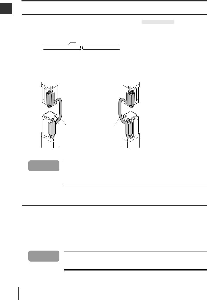
Series connection cable
|
|
|
|
|
|
Shape |
Model |
Length |
|||||||
|
|
|
|
|
|
|
|
|
|
|
|
|
SL-VS0 |
0.08 m |
|
|
|
|
|
|
|
(Transmitter/receiver set) |
|
|
|||||||
SL-VS01 |
0.15 m |
||||||||||||||
|
|
|
|
|
|
|
|
|
|
|
|
|
|
|
|
|
|
|
|
|
|
φ 5.8 |
|
|
|
|
|
|
SL-VS05 |
0.5 m |
|
|
|
|
|
|
|
|
|
|
|
|
|
|
|
||
SL-VS1 |
1 m |
||||||||||||||
|
|
|
|
|
|
|
|
|
|
|
|
|
|||
|
|
|
|
|
|
|
|
|
|
|
|
|
|
|
|
|
|
|
|
|
|
|
|
|
|
|
|
|
SL-VS3 |
3 m |
|
|
|
|
|
|
|
|
|
|
|
|
|
|
SL-VS10 |
10 m |
|
|
|
|
|
|
|
|
|
|
|
|
|
|
|
|
|
Figure of series connection
Transmitter |
Receiver |
Sub unit 1 |
Sub unit 1 |
Main unit |
Series connection cable |
|
Series connection cable |
||
|
Main unit
 Danger If a series connection cable has been cut or extended, it is not allowed to be used for the SL-V. Use of a cut or extended cable may cause the safety function not to operate properly and may cause a dangerous situation.
Cable length specification
When using the unit connection cable, junction cable and extension cable together, the sum of the length for all the cables must be 30 m or less. This limitation is applicable to each unit, transmitter and receiver, respectively. Since up to 3 of the SL-V units can be connected in series, up to 2 sets of series connection cables are possible. Two sets of the SL-VS10 cables (cable length: 10 m) can be used. In this case, the sum length of all types of cables, including the series connection cable, must be 50 m or less. This limitation is also applicable to each unit, transmitter and receiver, respectively.
 Danger Cables must be within the lengths specified. Failure to follow this specification may cause improper operation of safety function, and may cause a dangerous situation.
1-6 |
SL-V-M-NO1-E |
1-2 Options
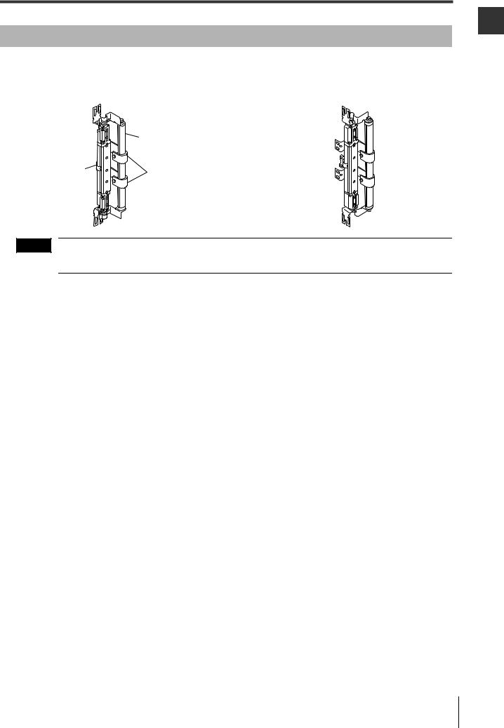
Protection bar
This is an option that protects the detection surface of the SL-V against contacting workpieces. It can be used with SL-VF/VH/VL.
Back mounting view when combined |
Side mounting view when combined |
|
Bar (Material: Aluminum) |
|
Use a compact E-to- |
Protection bar |
|
E mounting bracket |
||
intermediate support bracket |
||
(OP-83181) as the |
||
(Material: SUS304) |
||
intermediate support |
||
|
||
mounting bracket for |
|
|
the SL-V |
|
NOTE |
The above figures show the state when standard mounting bracket A is combined. The unit can also be |
combined with standard mounting bracket B, C, and J.
Protection bar
The model longer than the length of the SL-JB71 includes the required number of the intermediate support brackets.
Model |
Name |
|
Applicable model |
|
The required number of intermediate |
||
|
|
support brackets for protection bar |
|||||
|
|
|
|
|
|
|
|
SL-JB15 |
Protection bar 150 mm (x1) |
- |
|
SL-V08H |
|
Sl-V04L |
0 |
|
|
|
|
|
|
|
|
SL-JB23 |
Protection bar 230 mm (x1) |
SL-V23F |
|
SL-V12H |
|
SL-V06L |
0 |
|
|
|
|
|
|
|
|
SL-JB31 |
Protection bar 310 mm (x1) |
SL-V31F |
|
SL-V16H |
|
SL-V08L |
0 |
|
|
|
|
|
|
|
|
SL-JB39 |
Protection bar 390 mm (x1) |
SL-V39F |
|
SL-V20H |
|
SL-V10L |
0 |
|
|
|
|
|
|
|
|
SL-JB47 |
Protection bar 470 mm (x1) |
SL-V47F |
|
SL-V24H |
|
SL-V12L |
0 |
|
|
|
|
|
|
|
|
SL-JB55 |
Protection bar 550 mm (x1) |
SL-V55F |
|
SL-V28H |
|
SL-V14L |
0 |
|
|
|
|
|
|
|
|
SL-JB63 |
Protection bar 630 mm (x1) |
SL-V63F |
|
SL-V32H |
|
SL-V16L |
0 |
|
|
|
|
|
|
|
|
SL-JB71 |
Protection bar 710 mm (x1) |
SL-V71F |
|
SL-V36H |
|
SL-V18L |
1 |
|
|
|
|
|
|
|
|
SL-JB79 |
Protection bar 790 mm (x1) |
SL-V79F |
|
SL-V40H |
|
SL-V20L |
1 |
|
|
|
|
|
|
|
|
SL-JB87 |
Protection bar 870 mm (x1) |
SL-V87F |
|
SL-V44H |
|
SL-V22L |
1 |
|
|
|
|
|
|
|
|
SL-JB95 |
Protection bar 950 mm (x1) |
SL-V95F |
|
SL-V48H |
|
SL-V24L |
1 |
|
|
|
|
|
|
|
|
SL-JB103 |
Protection bar 1030 mm (x1) |
SL-V103F |
|
SL-V52H |
|
SL-V26L |
1 |
|
|
|
|
|
|
|
|
SL-JB111 |
Protection bar 1110 mm (x1) |
SL-V111F |
|
SL-V56H |
|
SL-V28L |
1 |
|
|
|
|
|
|
|
|
SL-JB119 |
Protection bar 1190 mm (x1) |
SL-V119F |
|
SL-V60H |
|
SL-V30L |
1 |
|
|
|
|
|
|
|
|
SL-JB127 |
Protection bar 1270 mm (x1) |
SL-V127F |
|
SL-V64H |
|
SL-V32L |
1 |
|
|
|
|
|
|
|
|
SL-JB143 |
Protection bar 1430 mm (x1) |
- |
|
SL-V72H |
|
SL-V36L |
2 |
|
|
|
|
|
|
|
|
SL-JB159 |
Protection bar 1590 mm (x1) |
- |
|
SL-V80H |
|
SL-V40L |
2 |
|
|
|
|
|
|
|
|
SL-JB175 |
Protection bar 1750 mm (x1) |
- |
|
SL-V88H |
|
SL-V44L |
2 |
|
|
|
|
|
|
|
|
SL-JB191 |
Protection bar 1910 mm (x1) |
- |
|
SL-V96H |
|
SL-V48L |
2 |
|
|
|
|
|
|
|
|
SL-JB207 |
Protection bar 2070 mm (x1) |
- |
|
SL-V104H |
|
SL-V52L |
3 |
|
|
|
|
|
|
|
|
SL-JB223 |
Protection bar 2230 mm (x1) |
- |
|
SL-V112H |
|
SL-V56L |
3 |
|
|
|
|
|
|
|
|
SL-JB239 |
Protection bar 2390 mm (x1) |
- |
|
SL-V120H |
|
SL-V60L |
3 |
|
|
|
|
|
|
|
|
Accessories:
Bar x1, bar bracket x2, hexagon socket bolt (width across flat: 5 mm, length: 15 mm) x2
The required number of the intermediate support bracket for the protection bar (2 types :for back mounting and side mounting)
1
Use Before
SL-V-M-NO1-E |
1-7 |
1-2 Options
1
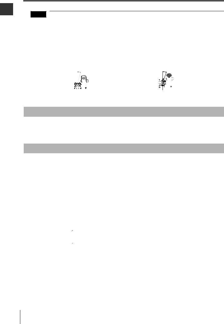
NOTE
Use Before
•To mount the protection bar to the SL-V, standard mounting bracket A (OP-42347), B (OP-42348), C (OP-42349), or J (OP-83180) is required.
•The bar and the standard mounting bracket are fixed with the hexagon socket bolts, so the angle of the mounting bracket or the bar cannot be adjusted. However, the angle of the SL-V and the mounting bracket can be adjusted for beam axis adjustment.
•The protection bar can be mounted to the back or side of the SL-V. Select an appropriate intermediate support for the protection bar based on the mounting method.
•Install the unit at the angle shown in the following figure so that the protection bar or the intermediate
support bracket does not block the beam axes of the SL-V.
Back mounting |
Side mounting |
|
|
15 |
|
|
|
|
|
|
|
|
|
|
|
|
|
20˚ |
|
|
|
|
||||||||||||
|
|
|
|
|
|
|
|
|
|
|
|
|
|
|
|
|
|
|
|
|
|
|
|
|
|
|
|
|
|
|
|
|
|
|
|
|
|
|
|
|
|
|
|
|
|
|
|
|
|
|
|
|
|
|
|
|
|
|
|
|
|
|
|
|
|
|
|
|
|
|
|
|
|
|
|
|
|
|
|
|
|
|
|
|
|
|
|
|
|
|
|
|
|
|
|
|
|
|
|
|
|
|
|
|
|
|
|
|
|
|
|
|
|
|
|
|
|
|
|
|
|
|
|
|
|
|
|
|
|
|
|
Front protection cover and dimmer filter
KEYENCE can provide the front protection cover to protect the surface of the SL-V and also provide the dimmer filter to shorten the operating distance.
Since these are optional, please contact your nearest KEYENCE office for further information.
SL-V Configurator (SL-VH1S)
When the SL-V Configurator is used, the following setting changes and functions are available.
Items |
|
Description |
Refer to page |
|
Muting function |
You can select the beam axes to be muted. The muting conditions can also be changed. |
2-29 |
||
|
|
|
||
|
You can change the setting whether or not to use the Muting bank function. |
|
||
Muting bank function |
When the muting bank function is used, the override function is disabled. Set |
2-32 |
||
the interlock function with the SL-V Configurator because setting of the |
||||
|
|
|||
|
interlock function with wiring is disabled. |
|
||
|
|
|
||
Override function |
You can change the override condition. |
2-45 |
||
|
|
|
||
|
The Interlock function enables OSSD to hold the OFF-state if no interruptions |
|
||
|
are present in the detection zone upon startup (when the power turns on or the |
|
||
|
lockout error condition is terminated by the reset input) or upon restart (when |
|
||
|
the SL-V is interrupted and the OSSD becomes the OFF-state). This state is |
|
||
|
called "interlock ". To recover from the interlock condition, the reset input must |
|
||
|
be switched ON to OFF while no interruptions are present in the detection |
|
||
Interlock function |
zone. Automatic or manual can be selected individually for start and restart. |
2-7 |
||
|
Automatic start mode |
: The OSSD automatically enters the ON-state when |
|
|
|
|
no interruptions are present in the detection zone. |
|
|
|
Manual start mode |
: Enters interlock condition upon startup. |
|
|
|
Automatic reset mode : The OSSD automatically returns to the ON-state when |
|
||
|
|
no interruptions are present in the detection zone. |
|
|
|
Manual reset mode |
: Enters interlock condition upon restart. |
|
|
|
|
|
||
|
This function is enabled only for the specified beam axes. The OSSD can hold |
|
||
|
the ON-state even when an interruption is present in the area. A desired area |
|
||
|
can be set as an effective zone of this function on a pair of transmitter and the |
|
||
Fixed blanking function |
receiver as well as on the all beam axes including the SL-V connected in |
2-48 |
||
|
series. The area where this function is enabled can be set as desired not only |
|
||
|
between a transmitter-receiver pair, but also on all the beam axes including the |
|
||
|
SL-V connected in series. |
|
||
|
|
|
|
|
1-8 |
SL-V-M-NO1-E |
1-2 Options
|
|
|
1 |
|
Items |
Description |
Refer to page |
|
|
Reduced resolution |
The OSSD holds the ON-state when the object is blocking only a specified |
|
|
Before |
the OSSD turns OFF only when the object is blocking more beam axes than |
|
|
||
|
number of beam axes (one beam axis to the half of all axes can be set), and |
|
|
|
function |
the specified number. This function is effective not only for a transmitter- |
2-49 |
|
Use |
|
|
|||
|
|
|
||
|
receiver pair, but also all the beam axes including the SL-V connected in |
|
|
|
|
series. |
|
|
|
|
|
|
|
|
Center indicator |
You can change the conditions for the center indicator to turn on, off, or blink. |
6-6 |
|
|
|
|
|
|
|
EDM function |
You can change the setting whether or not to use the EDM function. The |
2-15 |
|
|
tolerance time of the EDM input can also be changed. |
|
|
||
|
|
|
|
|
|
|
|
|
|
State information output |
You can change the output methods and the pulse time of the state information output. |
2-18 |
|
|
|
|
|
|
|
Emitting cycle change |
You can change the laser emission cycle. The SL-V units with different laser |
3-8 |
|
|
emission cycle can reduce the chance of mutual interference. |
|
|
||
|
|
|
|
|
|
|
|
|
|
Alert output monitoring |
You can change for how many seconds the unstable clear state can continue |
2-26 |
|
|
time change |
before issuing an alert output (alert output monitoring time). |
|
|
|
|
|
|
||
|
|
|
|
|
Monitor function |
You can monitor the received light intensity of each beam axis on the SL-V. |
2-50 |
|
|
|
|
|
|
|
Create/Save configuration
Upload configuration
Computer |
Download configuration |
Monitor light intensity
SL-V Series Ver.3
•You can create the configuration on the SL-V Configurator.
If you upload or download the configuration to or from the SL-V, you must connect the computer to the SL-V.
•The SL-V that must be connected to the computer for configuration is only receiver on the main unit.
Note |
• The SL-V1UB, USB 1.1-compatible USB cable (supplied with the SL-V1UB) and the SL-V unit |
|
|
|
connection cable are required for connection between the SL-V and the computer. |
•The main unit must be a Ver.3 if you want to configure something through the SL-V Configurator. In this case, the sub unit is not necessary to be Ver.3.
•The SL-VHS Series can not be used as the main unit.
•The OSSD goes to the OFF-state while the SL-V is connected to the SL-V1UB. You must disconnect the SL-V1UB from the SL-V after uploading or downloading the configuration.
SL-V-M-NO1-E |
1-9 |

1
Use Before
1-3 Part Description
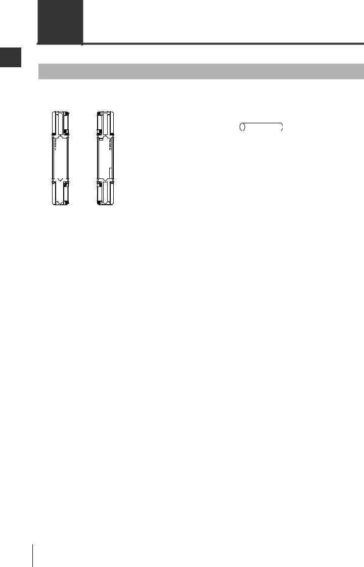
SL-V main unit
Transmitter |
Receiver |
The connector and connector cover for the |
|
|
Beam center-line mark |
|
|
SL-VFM/VHM/VLM are located on the back |
|||
|
|
|
|
side. |
|
|||
|
|
|
(upper) |
|
|
|
||
Top*1 |
|
( |
page 1-11 details) |
|
|
Transmitter |
Receiver |
|
|
|
|
|
|
|
|||
|
|
|
Connector cover |
|
|
|
Connector cover |
|
|
|
|
|
|
|
|
||
|
LEVEL |
|
|
LEVEL |
|
|
|
|
|
5 |
Installation reference mark |
5 |
|
|
|
||
|
4 |
4 |
|
|
|
|||
|
3 |
( |
page 3-4 details) |
3 |
|
|
|
|
Detection |
2 |
|
Indicators |
2 |
Detection |
|
|
|
1 |
|
1 |
Detection |
Detection |
||||
|
surface |
|||||||
surface |
|
|
||||||
|
|
|
|
|||||
|
|
|
|
-SL |
surface |
surface |
||
-SL |
WAIT |
|
|
MUTE1 |
||||
V08H |
( |
page 6-1 details) |
V08H |
|||||
FUNCTION |
MUTE2 |
|
|
|||||
ø25 |
OSSD |
Installation reference mark |
OSSD |
ø25 |
|
|
||
.(0 |
LOCK |
LOCK |
.(0 |
|
|
|||
|
INTER |
|
|
INTER |
|
|
|
|
98") |
|
|
|
|
98") |
|
Connector |
|
|
|
|
|
|
|
|
||
|
|
|
|
|
|
|
receptacle |
|
Bottom |
|
Connector receptacle |
|
|
|
|
||
|
|
|
|
|
|
|
||
Beam center-line mark (lower)
*1 The side where the connector cover has already been installed at shipment is the top side.
With options installed
Mounting bracket (option)
Mounting bracket (option)
(  page 3-15)
Unit connection cable on the receiver (option)
(  page 3-11)
Mounting bracket (option)
Unit connection cable on the transmitter (option)
(  page 3-11)
|
Function of each I/O line |
( |
page 2-3) |
Mounting bracket |
Power supply |
( |
page 4-2) |
(option) |
External device connection |
( |
page 4-1) |
1-10 |
SL-V-M-NO1-E |
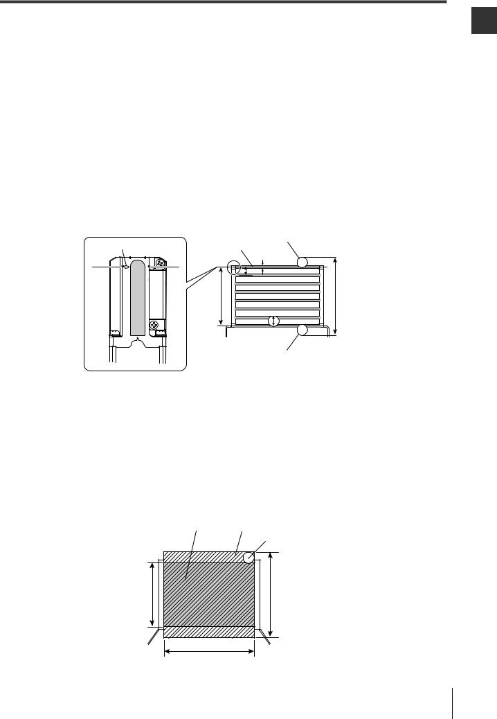
1-3 Part Description
Beam center-line : An optical path joining the optical center of the emitting element on the transmitter to the optical center of the corresponding receiving element on the receiver. the SL-V must be installed so that the beam center-line mark on the transmitter and that on the receiver face one another and are located at the same height.
Detection height : The height from the top beam center-line to the bottom beam center-line (length). Protection height : An object approaching the detection zone from the top of the detection height is first
detected at point A, which is the distance of the detection capability from the top of the detection height. The equivalent position on the bottom is called point B. The height from the top edge of the specified detection capability that exists at point A to the bottom edge of the specified detection capability that exists at point B is called a "protection height".
The following calculation formula can be defined:
Protection height = "Detection height" + 2 x "the specified detection capability"–"beam axis diameter".
* Refer to the following diagram for an explanation of beam center-line, detection height and protection height.
|
|
Specified detection capability (position A) |
|
Beam center-line mark |
Beam center-line |
||
|
|
b |
|
|
a |
|
|
Detection |
|
Protection height |
|
height |
|
|
|
|
|
c |
|
a: Beam axis spacing |
|
||
b: Beam axis diameter |
Specified detection capability (position B) |
||
c: Detection capability |
|||
|
|||
Detection zone: |
The zone in which the specified detection capability can be detected. The detection zone |
|
of the SL-V indicates a square area formed with the detection height and the operating |
|
distance. When a part or whole of the specified detection capability is present in this area, |
|
the light of the SL-V is blocked, and then the OSSD goes to OFF state. |
Protection zone: |
The square area formed with the protection height and the operating distance, which |
|
is broader than the detection zone. When a whole of the specified detection capabil- |
|
ity is present in this area, the light of the SL-V is blocked, and then the OSSD goes to |
|
OFF state. |
* Refer to the following diagram for detection zone and protection zone.
Detection zone |
Protection zone |
Specified detection capability
Detection |
Protection |
height |
height |
Operating distance
1
Use Before
SL-V-M-NO1-E |
1-11 |

1-3 |
Part Description |
||
|
|
|
|
|
|
|
|
1 |
|
|
MEMO |
|
|
|
|
Use Before |
|
||
1-12 |
SL-V-M-NO1-E |

2
Functions and Features
2-1 Cable Selection and Function . . . . . . . . . . . . . . . . . . . . . . . . . 2-2
2-2 Self-diagnosis Function . . . . . . . . . . . . . . . . . . . . . . . . . . . . . . 2-4
2-3 Series Connection . . . . . . . . . . . . . . . . . . . . . . . . . . . . . . . . . . 2-6
2-4 Interlock Function . . . . . . . . . . . . . . . . . . . . . . . . . . . . . . . . . . 2-7
2-5 AUX (Auxiliary) Output. . . . . . . . . . . . . . . . . . . . . . . . . . . . . . 2-14
2-6 External Device Monitoring (EDM Function) . . . . . . . . . . . . . 2-15
2-7 Wait Input Function . . . . . . . . . . . . . . . . . . . . . . . . . . . . . . . . 2-16
2-8 State Information Output . . . . . . . . . . . . . . . . . . . . . . . . . . . . 2-18
2-9 Alert Output . . . . . . . . . . . . . . . . . . . . . . . . . . . . . . . . . . . . . . 2-25
2-10 Clear/Blocked Output. . . . . . . . . . . . . . . . . . . . . . . . . . . . . . . 2-27
2-11 Temporary Suspension of Safety Function . . . . . . . . . . . . . . 2-29
2-12 Fixed Blanking . . . . . . . . . . . . . . . . . . . . . . . . . . . . . . . . . . . . 2-48
2-13 Reduced Resolution . . . . . . . . . . . . . . . . . . . . . . . . . . . . . . . 2-49
2-14 I/O Monitoring Function . . . . . . . . . . . . . . . . . . . . . . . . . . . . . 2-50
SL-V-M-NO2-E |
2-1 |

2
Features and Functions
2-1 Cable Selection and Function
Functions
There are two types of cables that can be used with the SL-V. One is simple function type and another is multi-function type. The type of cable used determines the functions that can be used. (The number of wires is different from each other.) Additionally, there are functions that can be activated with or without the SL-V Configurator (SL-VH1S). Refer to the following chart.
|
|
|
Usable functions |
|
|
||
Function and overview |
|
Simple function |
|
Multi-function type |
|
Page |
|
|
|
|
type cable |
|
cable |
|
|
[Self-diagnosis] |
|
X |
|
X |
|
2-4 |
|
Detects a failure to the SL-V. |
|
|
|
||||
|
|
|
|
|
|
||
|
|
|
|
|
|
|
|
[Series connection] |
|
|
|
|
|
|
|
Expands the protection zone with the SL-V |
|
X |
|
X |
|
2-6 |
|
connected in series. |
|
|
|
|
|
|
|
|
|
|
|
|
|
|
|
[Interlock] |
|
|
|
|
|
|
|
The SL-V prevents the OSSD from automatically |
(X) |
|
(X) |
|
2-7 |
||
going to the ON-state. |
|
|
|
|
|
|
|
|
|
|
|
|
|
|
|
[EDM] |
|
X |
|
X |
|
2-15 |
|
Detects a failure on external devices. |
|
|
|
||||
|
|
|
|
|
|
||
|
|
|
|
|
|
|
|
[Wait input] |
|
|
|
|
|
|
|
Puts the OSSD into an OFF-state through a signal |
X |
|
X |
|
2-16 |
||
from an external device. |
|
|
|
|
|
|
|
|
|
|
|
|
|
|
|
[AUX (auxiliary) output] |
|
X |
|
X |
|
2-14 |
|
Output for OSSD monitors. |
|
|
|
||||
|
|
|
|
|
|
||
|
|
|
|
|
|
|
|
[State Information output] |
|
|
|
|
|
|
|
Informs the external devices of the current state of |
- |
|
X |
|
2-18 |
||
the SL-V. |
|
|
|
|
|
|
|
|
|
|
|
|
|
|
|
[Alert output] |
|
|
|
|
|
|
|
Informs the external devices when the amount of |
- |
|
X |
|
2-25 |
||
receiving light is decreased. |
|
|
|
|
|
|
|
|
|
|
|
|
|
|
|
[Clear/Blocked output] |
|
|
|
|
|
|
|
Informs to the external devices whether beam axis is |
- |
|
X |
|
2-27 |
||
clear or blocked. |
|
|
|
|
|
|
|
|
|
|
|
|
|
|
|
[Muting/Override] |
|
- |
|
(X) |
|
2-29 |
|
Temporary suspension of safety function. |
|
|
|
||||
|
|
|
|
|
|
||
|
|
|
|
|
|
|
|
[Fixed blanking] |
|
|
|
|
|
|
|
Keeps the OSSD ON-state even when an obstacle is |
S |
|
S |
|
2-48 |
||
in a protection zone. |
|
|
|
|
|
|
|
|
|
|
|
|
|
|
|
[Reduced resolution] |
|
|
|
|
|
|
|
Keeps the OSSD ON-state even if the moving |
S |
|
S |
|
2-49 |
||
obstacle is in the protection zone. |
|
|
|
|
|
|
|
|
|
|
|
|
|
|
|
[I/O monitoring function] |
|
|
|
|
|
|
|
Informs the user of the state of several I/Os on the |
X |
|
X |
|
2-50 |
||
SL-V through the indicators of the SL-V. |
|
|
|
|
|
|
|
|
|
|
|
|
|
|
|
[Emitting cycle change] |
|
S |
|
S |
|
3-8 |
|
Reduces the possibility of light interference. |
|
|
|
||||
|
|
|
|
|
|
||
|
|
|
|
|
|
|
|
[Center Indicator] |
|
(X) |
|
(X) |
|
6-6 |
|
Lights to indicate the condition of the SL-V. |
|
|
|
||||
|
|
|
|
|
|
||
|
|
|
|
|
|
|
|
|
|
|
|
||||
|
X : |
This function can be used without the SL-V Configurator |
|
||||
|
(X) : Parts of this function can be used without the SL-V Configurator |
||||||
|
S : |
The SL-V Configurator is required |
|
||||
|
- : |
This function is not available. |
|
|
|
||
|
|
|
|
|
|
|
|
2-2 |
SL-V-M-NO2-E |
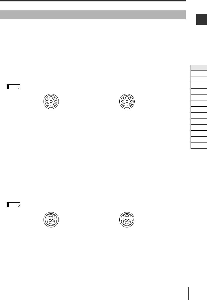
2-1 Cable Selection and Function
Cable color and pin assignment
Simple function type
|
|
Transmitter |
Pin No. |
Wire color |
Assigned function |
1 |
Pink |
Interlock mode selection input |
|
|
|
2 |
Brown |
+24 V |
|
|
|
3 |
Violet |
Wait input |
|
|
|
4 |
Green |
Interlock-reset-ready output |
|
|
|
5 |
Orange |
Communication cable 1 (RS485_+) |
|
|
|
6 |
Orange/Black |
Communication cable 2 (RS485_-) |
|
|
|
7 |
Blue |
0 V |
|
|
|
8 |
Red |
AUX (auxiliary) output |
|
|
|
|
|
Receiver |
Pin No. |
Wire color |
Assigned function |
1 |
White |
OSSD 2 |
|
|
|
2 |
Brown |
+24 V |
|
|
|
3 |
Black |
OSSD 1 |
|
|
|
4 |
Yellow |
RESET input |
|
|
|
5 |
Orange |
Communication cable 1 (RS485_+) |
|
|
|
6 |
Orange/Black |
Communication cable 2 (RS485_-) |
|
|
|
7 |
Blue |
0 V |
|
|
|
8 |
Red |
EDM input |
|
|
|
Reference M12 connector male pin assignment |
M12 connector female pin assignment |
||||
|
2 |
1 |
|
1 |
2 |
3 |
8 |
7 |
7 |
8 |
3 |
|
4 |
6 |
|
6 |
4 |
|
5 |
|
|
5 |
|
Multi-function type
|
|
Transmitter |
Pin No. |
Wire color |
Assigned function |
1 |
Pink |
Interlock mode selection input*1 |
2 |
Brown |
+24 V |
|
|
|
3 |
Violet |
Wait input*1*2 |
4 |
Green |
Interlock-reset-ready output |
|
|
|
5 |
Orange |
Communication cable 1 (RS485_+) |
|
|
|
6 |
Orange/Black |
Communication cable 2 (RS485_-) |
|
|
|
7 |
Blue |
0 V |
|
|
|
8 |
Red |
AUX (auxiliary) output |
|
|
|
9 |
Grey |
State information output 1 |
|
|
|
10 |
Grey/Black |
State information output 2 |
|
|
|
11 |
Pink/Black |
Alert output |
|
|
|
12 |
White/Black |
Clear/Blocked Output |
|
|
|
|
|
Receiver |
Pin No. |
Wire color |
Assigned function |
1 |
White |
OSSD 2 |
|
|
|
2 |
Brown |
+24 V |
|
|
|
3 |
Black |
OSSD 1 |
|
|
|
4 |
Yellow |
RESET input |
|
|
|
5 |
Orange |
Communication cable 1 (RS485_+) |
|
|
|
6 |
Orange/Black |
Communication cable 2 (RS485_-) |
|
|
|
7 |
Blue |
0 V |
|
|
|
8 |
Red |
EDM input |
|
|
|
9 |
Red/Black |
Override input*1*2 |
10 |
Yellow/Black |
Muting lamp output |
|
|
|
11 |
Light blue |
Muting input 1 |
|
|
|
12 |
Light blue/Black |
Muting input 2 |
|
|
|
Reference M14 connector male pin assignment |
M14 connector female pin assignment |
|||||||||
|
2 |
|
|
1 |
|
|
1 |
|
2 |
|
3 |
|
10 |
|
9 |
9 |
10 |
|
3 |
||
4 |
11 |
12 |
8 |
8 |
12 |
11 |
4 |
|||
|
5 |
6 |
|
7 |
|
|
7 |
6 |
5 |
|
|
|
|
|
|
|
|
|
|
||
*1 The following changes apply when the muting bank function is enabled.
Pink: Muting bank input 3, Violet: Muting bank input 1, Red/black: Muting bank input 2  "Muting function" (page 2-29)
*2 If the center indicator is set to the Built-in indicator mode, this is used for the control input of the indication state.
 "Center Indicator" (page 6-6)
2
Features and Functions
Cable
Self-diagnosis
Series Connection
Interlock
AUX
EDM
Wait
State Information
Alert
Clear/Blocked
Suspension
Fixed
Reduced
Monitoring
SL-V-M-NO2-E |
2-3 |

2
Features and Functions
2-2 Self-diagnosis Function
Lockout condition
The SL-V performs self-diagnosis for approx. 4.5 seconds after the power is turned on and checks for errors in the SL-V. Self-diagnosis is also performed periodically during normal operations.
If the self-diagnosis function detects an error, the SL-V goes to Lockout condition and the OSSD is kept in OFF state even if no interruption exists in the detection zone. The indicators operate in the following man-
ner during lockout condition. |
|
|
Bar LED |
: Indication corresponding to the cause of the error |
|
|
|
See "Troubleshooting" (page A-2) |
|
|
|
Function indicator |
: Interlock indicator is blinking in yellow. |
|
|
|
See "Function Indicators" (page 6-5) |
|
|
|
Center indicators |
: All indicators are blinking in red. |
|
|
|
See "Center Indicator" (page 6-6) |
|
|
|
To release the lockout condition, first remove the cause of the error, and then either activate reset input or turn the power off and on again.
 See "Time chart for the termination of lockout condition due to reset input" (page 2-13)
Self-diagnosis description
Transmitter
•Error in external power supply voltage
•Failure in internal power supply circuit
•Failure in light emitting element and light receiving circuit
•CPU overdrive
•Memory error
•Cable open/short-circuit
Receiver
•Error in external power supply voltage
•Failure in internal power supply circuit
•Failure in light receiving element and detection circuit
•CPU overdrive
•Memory error
•Failure in safety output circuit (OSSD)
•Cable open/short-circuit
•Program monitoring
2-4 |
SL-V-M-NO2-E |
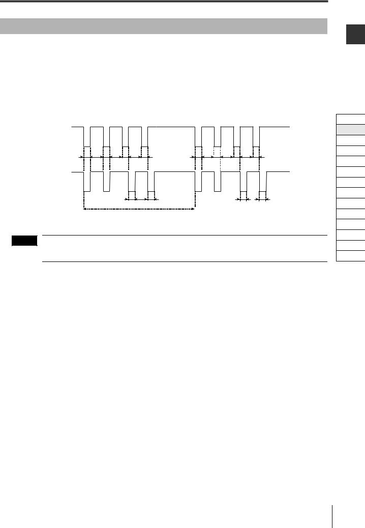
2-2 Self-diagnosis Function
OSSD
The OSSD is a safety-related control output. It connects to an external device (load), such as an FSD or MPCE. The SL-V generates self-diagnosis signals on its internal control circuit to perform diagnostics on the output circuit (OSSD). These signals periodically force the OSSD into a temporary OFF state when no interruption exists in the detection zone.
The internal control circuit receives a feed-back signal (OFF signal) based on the self-diagnosis, the SL- V determines that its output circuit is operating normally. If this OFF signal is not returned to the internal control circuit, the SL-V determines that there is a problem in its output circuit or wiring and goes to the lockout condition.
ON
OSSD1
OFF
A B A B A B A A B A B A B A
ON
OSSD2
OFF
A A A A
Approx. 100 ms
A : 60 μs max.
B : Approx. 10 ms
NOTE |
The devices connected to the OSSD, such as safety relay or contactor, should not respond to these tem- |
|
porary, self-diagnostic OFF-signals.
2
Features and Functions
Cable
Self-diagnosis
Series Connection
Interlock
AUX
EDM
Wait
State Information
Alert
Clear/Blocked
Suspension
Fixed
Reduced
Monitoring
SL-V-M-NO2-E |
2-5 |
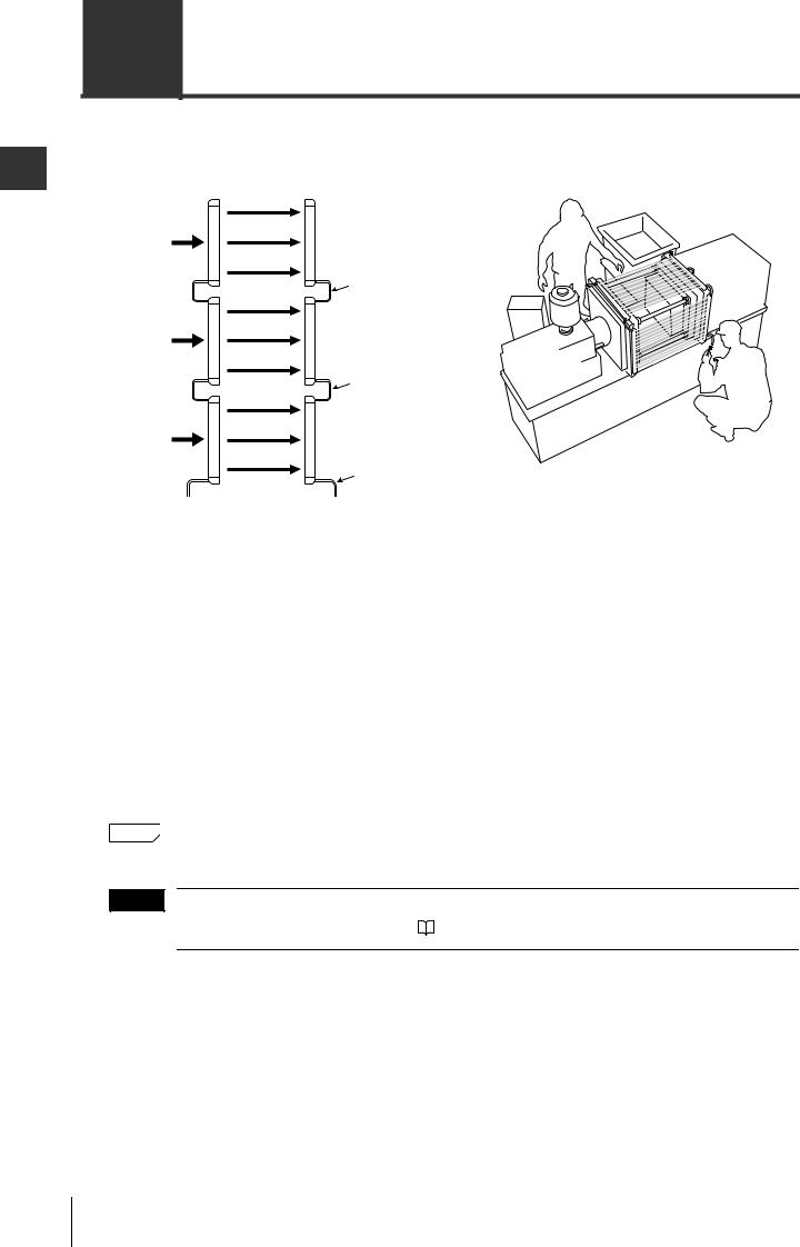
2
Features and Functions
2-3 Series Connection
Up to three SL-V units can be serially connected and used as a single light curtain. Use the series connection cables that KEYENCE provides as an optional part. (  See "Series connection cable" (page 1-6))
Example of use with 3 units in series connection
Sub unit 2 |
Transmitter |
Receiver |
|
|
Series connection |
|
|
cable |
|
Transmitter |
(10 m max.) |
Sub unit 1 |
Receiver |
|
|
|
|
|
|
Series connection |
|
|
cable |
|
Transmitter |
(10 m max.) |
Main unit |
Receiver |
|
|
|
|
|
|
Unit connection cable |
Benefits
•Prevents the light interference between the connected SL-Vs
•Simplified wiring because the wiring for OSSD or synchronization cable
•Combining the SL-VF (M), SL-VH (M) and the SL-VL (M) is allowable in series connections even though they have different respective detection capabilities.
Limitations
•Up to 3 units
•Up to 240 total number of beam axes
•The length of one series connection cable must be 10 m or less. When connecting three units in series, the total length of two cables must be 20 m or less.
 See "Cable Connections" (page 3-11).
|
Reference |
|
Even when series connection cannot be established, light interference is reduced by the light |
|
|||
|
|
|
interference prevention function. No special settings are required. |
NOTE |
Series connection is required for secure light interference prevention. When not connecting the SL-V units |
|
|
||
|
in series, install the units by referring to |
"Light Interference Prevention Method" (page 3-8) |
2-6 |
SL-V-M-NO2-E |
Loading...