


 Loading...
96M13428
Inline Static Sensor
SK-1000 Series
Instruction Manual
Read this instruction manual before using the product in order to achieve maximum performance.
Keep this manual in a safe place after reading it for future reference.
Introduction
This manual describes the operations of and information related to the SK-1000 Series.
Read this manual carefully to ensure the safe performance and function of the SK-1000 Series.
Keep this manual in a safe place for future reference.
Ensure that the end user of this product receives this manual.
Symbols
The following symbols are used in this instruction manual to enable you to recognize important information at a glance.
Be sure to read this section carefully.
|
|
|
|
Indicates a hazardous situation which, if not avoided, will result in |
|
DANGER |
|||
|
|
|
death or serious injury. |
|
|
|
|
|
|
|
|
|
|
|
|
|
|
|
Indicates a hazardous situation which, if not avoided, could result |
|
WARNING |
|||
|
|
|
in death or serious injury. |
|
|
|
|
|
|
|
|
|
|
|
|
|
|
|
Indicates a hazardous situation which, if not avoided, could result |
|
CAUTION |
|||
|
|
in minor or moderate injury. |
||
|
|
|||
|
|
|
|
|
|
NOTICE |
|
|
Indicates a situation which, if not avoided, could result in product |
|
|
|
damage as well as property damage. |
|
|
|
|
|
|
|
|
|
|
|
|
|
|
|
|
 Important Indicates cautions and limitations that must be followed during operation.
Point |
|
Indicates additional information on proper operation. |
|
||
|
|
|

 Reference Indicates tips for better understanding or useful information.
 Indicates the reference pages in this manual or the reference pages in separate manuals.
Table of Contents |
|
Introduction ...................................................................................... |
1 |
Safety Precautions ........................................................................................ |
2 |
General Precautions ......................................................................... |
2 |
Safety Information for the SK-1000 series ........................................ |
2 |
Abnormal Conditions ........................................................................ |
2 |
Precautions for Use .......................................................................... |
2 |
Other Precautions ............................................................................. |
2 |
Precautions for Regulations and Standards .................................................. |
2 |
1. Before Use ................................................................................................ |
3 |
Checking the Package Contents ...................................................... |
3 |
Part Names and Functions ............................................................... |
3 |
2. Installation and Connection ....................................................................... |
4 |
Mounting and Wiring the Sensor Amplifier ....................................... |
4 |
Connecting and Mounting the Sensor Head .................................... |
5 |
3. Basic Operations ....................................................................................... |
7 |
Operation When the Power is Turned on for the First Time .............. |
7 |
Operations on the Main Screens ...................................................... |
7 |
Initial Reset (Initialize) ....................................................................... |
8 |
Setting the Tolerance Values ............................................................ |
9 |
Zero Shift Function |
|
(Shifting the Internal Measurement Value (R.V.)) ............................. |
9 |
Bank Function (Registering Multiple Tolerance Setting Values) ...... |
9 |
Key Lock Function 10 |
|
4. Setting Various Functions ....................................................................... |
10 |
Basic Settings and Advanced Settings .......................................... |
10 |
Simulation Mode ............................................................................. |
17 |
5. Specifications .......................................................................................... |
17 |
Specifications ................................................................................. |
17 |
Circuit Diagram .............................................................................. |
18 |
Dimensions ..................................................................................... |
18 |
Response Time ............................................................................... |
19 |
6. Appendix ................................................................................................. |
19 |
Troubleshooting .............................................................................. |
19 |
Display Screen and Output ............................................................ |
21 |
Factory Setting (Default Value) List ................................................ |
21 |
1 |
E SK-1000 IM |
Safety Precautions
General Precautions
•At startup and during operation, be sure to monitor the functions and performance of this product and confirm normal operation.
•We recommend that you take substantial safety measures to avoid any damage in the event that a problem occurs.
•If the product is modified or used in any way other than those described in the specifications, its functions and performance cannot be guaranteed.
•When this product is used in combination with other devices, the functions and performance may be weakened, depending on the operating conditions, surrounding environment, etc.
•Do not use this product for the purpose of protecting the human body.
•Do not subject this device, including peripheral devices, to rapid temperature change. Product failure may occur due to condensation.
Safety Information for the SK-1000 series
• This product is only intended to detect the charge on object(s). Do not use this product for the purpose to protect a human body or a part of human body.
 WARNING • This product is not intended for use as explosion-proof product. Do not use this product in hazardous location and/or potentially explosive atmosphere.
Warming up
Leave the SK Series about 30 minutes after turning on the power.
The circuit is not stable immediately after the power turns on, so the display value may gradually fluctuate.
Abnormal Conditions
|
If the following conditions occur, turn OFF the power immediately. |
|
Continuing to use this product under abnormal conditions may |
NOTICE |
cause product failure. |
• When water or foreign matter enters the SK Series |
|
|
• When the SK Series is dropped or the case is damaged |
|
• If smoke or unpleasant odor is present. |
Precautions for Use
• Use with the correct power source and voltage. Otherwise, fire, electric shock or product failure may result.
 CAUTION • Do not attempt to open or modify the SK Series. Doing so may cause fire or electric shock.
•Before disconnecting the cables, make sure to turn off the main unit and devices connected to the main unit. Otherwise, the unit may be damaged.
•Do not turn off the power while modifying settings. Some or all
NOTICE |
of the setting data may be lost. |
|
•The measurement area is basically a guide for measurement. A proper size of target with respect to the measurement area is recommended to ensure a more accurate measurement.
Installation environment
To use this product normally and safely, do not install this product in the following locations. Product failure may occur.
•High-humidity, dusty or poorly-ventilated locations
•High-temperature locations where the unit is exposed to direct sunlight
•Locations where there is corrosive or combustible gas
•Locations where the unit may be directly subjected to vibration or impact
•Locations where water, oil or chemicals may splash onto the unit
•Locations that cause the unit to discharge its static electricity
Influence of dirt
Measurement errors may occur due to dust, water, oil, etc.
Anti-noise prevention
When the unit is installed near electric noise source such as a power source or high-voltage line, operational errors or product failure may occur. Take adequate measures such as using a noise filter, separating cables or insulating the sensor amplifier and the sensor head.
Power ON Reset
After the power is turned ON, it will take approx. 3.5 seconds for the measurement to start. The judgment results will be output after the sampling rate has elapsed.
Other Precautions
Power source
•Noise superimposed on the power supply may cause malfunction. Use a direct current stabilized power source which uses an insulation transformer.
•When using a commercially available switching regulator, make sure to ground the frame ground terminal.
Grounding precautions
A grounding wire is present in the I/O cable of the SK-1000 Series.
•For proper measurements, be sure to connect the blue wire NOTICE protruding from the SK-1000 Series to ground.
•Use class-D grounding-resistance not exceeding 100 Ω.
Precautions for Regulations and Standards
CE Marking
Keyence corporation has confirmed that this product complies with the essential requirements of the applicable EC Directives, based on the following specifications.
Be sure to consider the following specifications when using this product in the Member States of European Union.
z EMC Directive
• Applicable standards EN61326-1, ClassA
•This product is intended to be used in an industrial electromagnetic environment.
Remarks
These specifications do not give any guarantee that the end-product with this product incorporated complies with the essential requirements of EMC Directive. The manufacturer of the end-product is solely responsible for the compliance on the end-product itself according to EMC Directive.
FCC regulations
This product complies with the following EMI regulations specified by the FCC.
• Applicable standards |
FCC part 15 subpart B, class A digital device |
IC (Industry Canada) regulations
This product complies with the following EMI regulations specified by IC.
• Applicable standards |
ICES-003, class A digital apparatus |
E SK-1000 IM |
2 |

1. Before Use
This chapter gives an overview of the SK Series as well as the name and function of each part.
Checking the Package Contents
The following equipment and accessories are included in the package. Before using the unit, make sure that all items are included.
Sensor Amplifier
DIN rail mount type
|
|
|
|
|
|
|
|
|
|
|
|
|
|
|
|
|
|
|
|
|
|
|
|
|
|
|
|
|
|
|
|
|
|
|
|
|
|
SK- |
1000 |
(main |
|
unit) |
|
|
|
|
|
|
|
|
|
|
|
|
|
SK- |
1050 |
|
(expansion |
|
unit) |
|
|
|
|
|
|
|
|||
|
|
|
|
|
|
|
|
|
|
|
|
|
|
|
|
|
|
|
|
|
|
|
|
|
|
|
|
|
|
|
|
|
|
|
|
|
|
|
|
|
|
|
|
|
|
|
|
|
|
|
|
|
|
|
|
|
|
|
|
|
|
|
|
|
|
|
|
|
|
|
|
|
|
|
|
|
|
|
|
|
|
|
|
|
|
|
|
|
|
|
|
|
|
|
|
|
|
|
|
|
|
|
|
|
|
|
|
|
|
|
|
|
|
|
|
|
|
|
|
|
|
|
|
|
|
|
|
|
|
|
|
|
|
|
|
|
|
|
|
|
|
|
|
|
|
|
|
|
|
|
|
|
|
|
|
|
|
|
|
|
|
|
|
|
|
|
|
|
|
|
|
|
|
|
|
|
|
|
|
|
|
|
|
|
|
|
|
|
|
|
|
|
|
|
|
|
|
|
|
|
|
|
|
|
|
|
|
|
|
|
|
|
|
|
|
|
|
|
|
|
|
|
|
|
|
|
|
|
|
|
|
|
|
|
|
|
|
|
|
|
|
|
|
|
|
|
|
|
|
|
|
|
|
|
|
|
|
|
|
|
|
|
|
|
|
|
|
|
|
|
|
|
|
|
|
|
|
|
|
|
|
|
|
|
|
|
|
|
|
|
|
|
|
|
|
|
|
|
|
|
|
|
|
|
|
|
|
|
|
|
|
|
|
|
|
|
|
|
|
|
|
|
|
|
|
|
|
|
|
|
|
|
|
|
|
|
|
|
|
|
|
|
|
|
|
|
|
|
|
|
|
|
|
|
|
|
|
|
|
|
|
|
|
|
|
|
|
|
|
|
|
|
|
|
|
|
|
|
|
|
|
|
|
|
|
|
|
|
|
|
|
|
|
|
|
|
|
|
|
|
|
|
|
|
|
|
|
|
|
|
|
|
|
|
|
|
|
|
|
|
|
|
|
|
|
|
|
|
|
|
|
|
|
|
|
|
|
|
|
|
|
|
|
|
|
|
|
|
|
|
|
|
|
|
|
|
|
|
|
|
|
|
|
|
|
|
|
|
|
|
|
|
|
|
|
|
|
|
|
|
|
|
|
|
|
|
|
|
|
|
|
|
|
|
|
|
|
|
|
|
|
|
|
|
|
|
|
|
|
|
|
|
|
Sensor amplifier x 1 |
|
|
|
|
|
|
|
|
|
|
|
Sensor amplifier x 1 |
|
||||||||||||||||||||||||||||||||||||
|
|
|
|
|
|
|
|
|
|
|
|
|
|
|
|
|
|
|
|
|
|||||||||||||||||||||||||||||||||||||||
|
|
|
|
|
|
|
|
|
|
|
|
|
|
|
|
|
|
|
|
|
|||||||||||||||||||||||||||||||||||||||
|
|
|
|
|
|
|
|
|
|
Instruction manual x 1 |
|
|
|
|
|
|
|
|
|
|
|
|
|||||||||||||||||||||||||||||||||||||
|
|
|
|
|
|
|
|
|
|
|
|
|
|
|
|
|
|
|
|
|
|
|
|
|
|
|
|
|
|
|
|
|
|
|
|
|
|
|
|
|
|||||||||||||||||||
|
|
|
|
|
|
|
|
|
|
|
|
|
|
|
|
|
|
|
|
|
|
|
|
|
|
|
|
|
|
|
|
|
|
|
|
|
|
|
|
|
|
|
|
|
|
|
|
|
|
|
|
|
|
|
|
|
|
|
|
Sensor Head
SK-050
Sensor head x 1
List of Optional Parts
For sensor amplifier
 OP-26751 (for SK-1000/1050)
End unit x 2
For sensor head
OP-87056 |
(2 m) |
OP-87660 |
(2 m) |
OP-87057 |
(5 m) |
OP-87661 |
(5 m) |
OP-87058 |
(10 m) |
OP-87662 |
(10 m) |
OP87059 (20 m) |
OP87663 (20 m) |
||
Sensor head connection cable |
Sensor head connection cable |
||
(M8 straight connector) x 1 |
(M8 L-shaped connector) x 1 |
||
OP-84338 |
|
OP-87934 |
|
Sensor head |
|
|
|
cable connector x 2 |
Ion balance monitor unit |
||
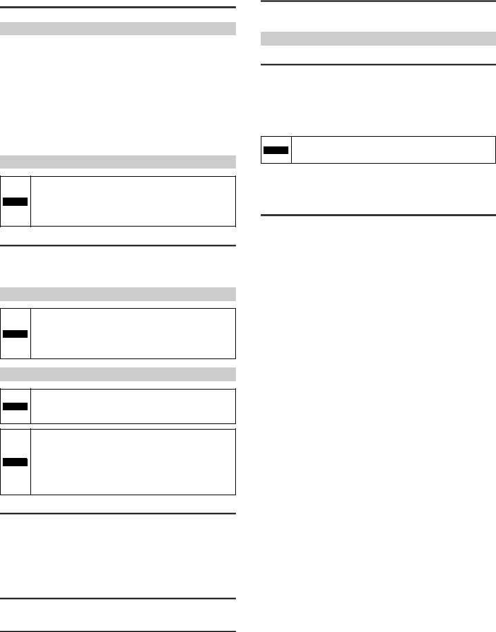
Part Names and Functions
Sensor Amplifier Unit
SK-1000
Expansion unit connector*1
|
|
|
|
Amplifier control unit cover |
|
|
V |
kV ALARM |
|
HOLD |
|
|
|
SELECT |
HI |
|
|
|
|
GO |
|
|
|
|
LO BANK 0 |
|
SET |
MODE |
|
|
1 |
|
||
|
2 |
|
|
|
|
3 |
|
|
|
|
TEMP |
%RH |
ZERO SHIFT |
|
ZERO SHIFT |
HI |
LO R.V. |
TIMING |
SK-1000 |
|
|
|
||
Amplifier control unit |
Expansion unit connector*2 |
|||
Sensor head connector |
|
|
||
*1 When shipped from the factory, a protective cover is installed over the expansion slots.
*2 Not installed on the main unit.
Amplifier control unit
|
(1) |
|
(15) |
(14) |
(13) |
|
|
|
|
|
|
|
|
|
|
|
|
|
|
|
(2) |
|
V |
kV |
ALARM |
|
|
|
|
|
HOLD |
|
|
|
|
|
|
SELECT |
|
|
(3) |
|
|
|
|
|
|
|
(12) |
|
(4) |
|
|
|
|
|
SET |
|
MODE |
|
|
|
|
|
|
|
|
|
|
|
|
|
|
ZERO SHIFT |
|
|
|
||
|
|
SHIFT |
|
|
TIMING |
|
-1000 |
|
|
|
|
|
|
|
|
|
|
||
|
(5) |
|
(6) |
(7) |
|
(8) |
(9) |
(10) |
(11) |
|
Item |
|
|
|
|
Description |
|
||
(1) |
Main display |
|
Displays the judgment value (P.V.) and each setting item. |
||||||
(2) |
HOLD indicator |
|
Lights up when the judgment value (P.V.) is held. |
||||||
|
"6. Hold Function" (page 12) |
|
|
|
|||||
|
|
|
|
|
|
||||
|
|
|
Displays whether the judgment value (P.V.) is HI (over the upper |
||||||
(3) |
Judgment indicator |
limit), GO (within the acceptable range) or LO (below the lower |
|||||||
limit) against the tolerance setting value. |
|
||||||||
|
|
|
|
||||||
|
|
|
"Changing the Tolerance Values" (page 9) |
|
|||||
|
|
|
Displays a bank in use. |
|
|
|
|
||
(4) |
Bank indicator |
|
"Bank Function (Registering Multiple Tolerance Setting Values)" |
||||||
|
|
|
(page 9) |
|
|
|
|
|
|
(5) |
Zero shift button |
Press this button to match the internal measurement value (R.V.) |
|||||||
to zero. |
|
|
|
|
|
|
|||
|
|
|
|
|
|
|
|
|
|
(6) |
Sub display indicator |
Lights up according to the type of values displayed on the sub |
|||||||
display. |
|
|
|
|
|
|
|||
(7) |
Sub display |
|
Displays the internal measurement value (R.V.), temperature, |
||||||
|
humidity, and each setting (selection) item. |
||||||||
|
|
|
|||||||
|
|
|
Lights up while the timing input is ON when the timing input |
||||||
(8)Timing input indicator (external input) is set to Level. Lights on approx. 0.5 sec. when
|
|
the timing input is set to Edge and the timing input is turned ON. |
|
|
|
|
|
(9) |
Zero shift indicator |
The zero shift indicator will light up for approx. 0.5 second when |
|
the zero shift function is used. |
|||
|
|
||
|
|
|
|
(10) |
SET button |
Used to perform initializations. |
|
|
|
|
|
(11) |
MODE button |
Used when setting items, entering/exiting setting modes or |
|
moving items. |
|||
|
|
||
|
|
|
|
(12) |
Arrow button |
Used when selecting settings, changing display contents on the |
|
sub display, etc. |
|||
|
|
||
|
|
|
|
(13) |
Alarm indicator |
Lights up in the alarm state or error state. |
|
|
|
|
|
(14) |
kV display unit |
Lights up when the judgment value (P.V.) display unit is kV. |
|
|
indicator |
|
|
(15) |
V display unit |
Lights up when the judgment value (P.V.) display unit is V. |
|
indicator |
|
|
|
|
|
|
|
|
|
|
|
|
|
|
|
|
|
|
|
|
|
|
|
|
|
|
|
|
|
|
|
|
|
|
|
|
|
|
|
|
|
|
|
|
|
|
|
|
|
|
|
|
|
|
|
3 |
E SK-1000 IM |
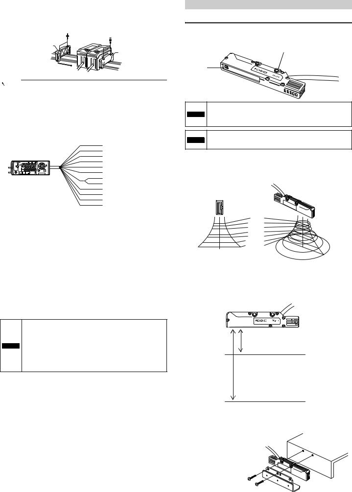
Sensor Head Unit
SK-050
(3) Temperature/humidity sensor
(1) Sensor indicator light
(2) Surface potential sensor
|
Item |
|
Description |
|
|
Lights up according to the judgment during normal operation. |
|
|
|
HI/LO: |
Lit in red |
(1) |
Sensor indicator light |
GO: |
Lit in green |
|
|
OFF: |
Off |
|
|
When an error occurs: |
Lit in red |
|
|
|
|
(2) |
Surface potential |
This sensor detects the charge potential. |
|
|
sensor |
|
|
(3) |
Temperature/humidity |
This sensor detects the temperature/humidity. |
|
sensor |
|||
|
|
|
|
2. Installation and Connection
This chapter describes precautions when installing and connecting the SK Series.
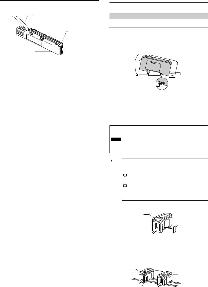
Mounting and Wiring the Sensor Amplifier
Mounting the Sensor Amplifier
SK-1000
1 Align the tab at the bottom of the amplifier body with the DIN rail. While pushing the amplifier in the direction of the arrow (1), push down in the direction of the arrow (2).

2 To dismount the sensor, raise the main body in the direction of the arrow (3) while pushing the main body in the direction of the arrow
(1).
Expansion unit (SK-1050)
Incorporate multiple units into one system by connecting expansion units to the main unit.
Up to 7 expansion units can be connected to one main unit.
•Always mount expansion units onto a DIN rail.
•When connecting multiple amplifiers (expansion units), first check to make sure that the power is turned OFF to all of the
NOTICE |
main and expansion units. Connecting the units with the power |
turned ON may cause damage to the units. |
•Position the amplifiers (expansion units) as close as possible to the main unit. Improper connections may damage the equipment.
Point |
• |
|
When connecting the expansion units, make sure to initialize the |
|
|
|
|
|
|
|
connected expansion units and set the output polarity. |
|
(1)Turning on the amplifier for the first time after connecting the |
||
|
|
|
sensor head |
|
|
|
"Operation When the Power is Turned on for the First Time" |
|
|
|
|
|
(page 7) |
||
|
(2)Performing the initial reset |
||
|
• |
|
"Initial Reset (Initialize)" (page 8) |
|
|
||
|
|
Expansion units with different setting of output polarity (such as |
|
|
|
|
an NPN output expansion unit and a PNP output main unit) |
|
|
|
cannot be connected together. |
1 Remove the expansion protective cover from the SK-1000 (main unit)
Main unit
Connector cover
2 Install the amplifiers (expansion units) on the DIN rail.
For details on how to install the unit, see the above explanation for the SK-1000.
3 Push the expansion unit into the main unit connector until a clicking sound can be heard.
The expansion unit installed next to the main unit is referred to as expansion unit 1. Subsequent expansion units are referred to as expansion unit 2, expansion unit 3, etc.
Main unit
Expansion unit
Connector
E SK-1000 IM |
4 |
4 Install the end units (OP-26751: 2 units in a set, optional accessory) on both sides of the amplifiers (main and expansion units). Secure the end units in place with screws on top (2 on each end unit).
The end units are mounted in the same way as the amplifiers.
End unit
End unit
Point |
|
Fix the amplifiers securely using the end units (OP-26751: 2 units |
|
|
|
|
|
in a set, optional accessory) or a commercially available DIN rail |
|
|
fixing tool to prevent the amplifiers from moving on the DIN rail or |
|
|
coming off of the DIN rail due to machine vibration. |
|
|
|
Power/Input-output cable
z "Output Circuit Diagram" (page 18)
|
|
|
Brown *1 |
10 to 30 VDC *4 |
|
|
|
Blue *1 |
|
|
|
|
0 V, grounding wire |
|
|
|
|
Black |
|
|
|
|
White |
HI judgment output |
|
|
|
LO judgment output |
|
HOLD |
V |
SELECT |
|
|
|
kV ALARM |
Gray |
|
|
HI |
|
|
GO judgment output |
|
GO LO |
BANK 10 |
SET MODE |
||
|
TEMP %RH |
ZERO SHIFT |
Green |
|
|
2 |
|
|
Alarm output |
|
3 |
|
|
|
ZERO SHIFT |
HI LO R.V. |
TIMING |
Orange *2 |
|
|
|
Light blue*1 |
Analog output (surface potential) |
|
|
|
|
Shield *2 |
|
|
|
|
Pink *3 |
Analog output GND |
|
|
|
Yellow *3 |
Zero shift input |
|
|
Pink/Purple *3 |
Reset input |
|
|
|
|
Purple *3 |
Timing input |
|
|
|
|
Bank A Input |
*1 The SK-1050 (expansion unit) does not have brown, blue, or light blue wires. Power is supplied to the expansion unit through the SK-1000 (main unit). Use D-class grounding to ground the blue wire.
*2 The analog output (surface potential) specifications change according to the measurement range.
The analog output can be set to one of the following values when the power is first turned on and when initializations are performed.
None (OFF), -5 to 5 V, 0 to 5 V, 1 to 5 V, or 4 to 20 mA
 " Operation When the Power is Turned on for the First Time" (page 7)
 " Initial Reset (Initialize)" (page 8)
*3 In addition to the above values, you can select from the following options for external input.
Bank B input or do not use (OFF)
 " 10. External input" (page 15)
*4 When you expand the system to 6 or more units, use a power supply voltage of 20 to 30 V.
•This device's 0 V power supply wire, analog output GND wire, and grounding wire are all shared. Ensure that an electric potential difference does not occur between their terminals due to wiring or due to electric potential differences between
NOTICE external devices. Failing to do so may lead to accidents or breakdowns involving the external devices and this product.
•Use power supplies that are isolated from each other or so that negative grounding is present between them. You cannot use positive grounding.
Connecting and Mounting the Sensor Head
Mounting the Sensor Head
Attach the sensor head using the dedicated mounting bracket.
When you attach the sensor head, be careful not to touch the aperture. Doing so may lead to malfunctions.
Mounting holes
Sensor unit
Tightening torque:
1.2 Nm (12kgf•cm) or less
Install the sensor unit (including its metal parts) so that nothing touches it during measurement. Failing to do so not only prevents
 WARNING proper measurements of static electricity but may also lead to electric shock and product breakdown.
Do not cover the area around the temperature/humidity sensing
NOTICE unit. Doing so will prevent you from correctly measuring the ambient temperature/humidity.
Measurement area
The following figures briefly show the measurement area of the SK-050.
The measured value is the average of the values detected within the measurement area as seen in the figures.
5 mm |
φ12 |
|
12 mm |
||
25 mm |
φ 30 |
|
φ 80 |
||
50 mm |
||
φ 200 |
||
60 mm |
||
φ 250 |
||
100 mm |
φ 500 |
|
120 mm |
φ 620 |
Measurement distance
The SK-050 provides a high-precision mode and a wide-range mode. Each mode offers different measurement distances between the sensor head and the target. The figure below shows the reference distance for measurements in each measurement mode. The reference plane is the bottom surface of the sensor head.
High-precision mode: 25 mm
Wide-range mode: 100 mm
Attaching the ion balance monitor unit (OP-87934)
Fix with screws using the mounting holes in the sensor's main body and those of the ion balance plate.
Tightening torque:
1.2 Nm (12kgf•cm) or less
5 |
E SK-1000 IM |
Be sure to fasten screws from the ion balance plate side. If
NOTICE fastened from the main body side, the ion balance plate can contact other parts, resulting in incorrect measurement.

 Reference The ion balance plate can be mounted from either side of the sensor head.
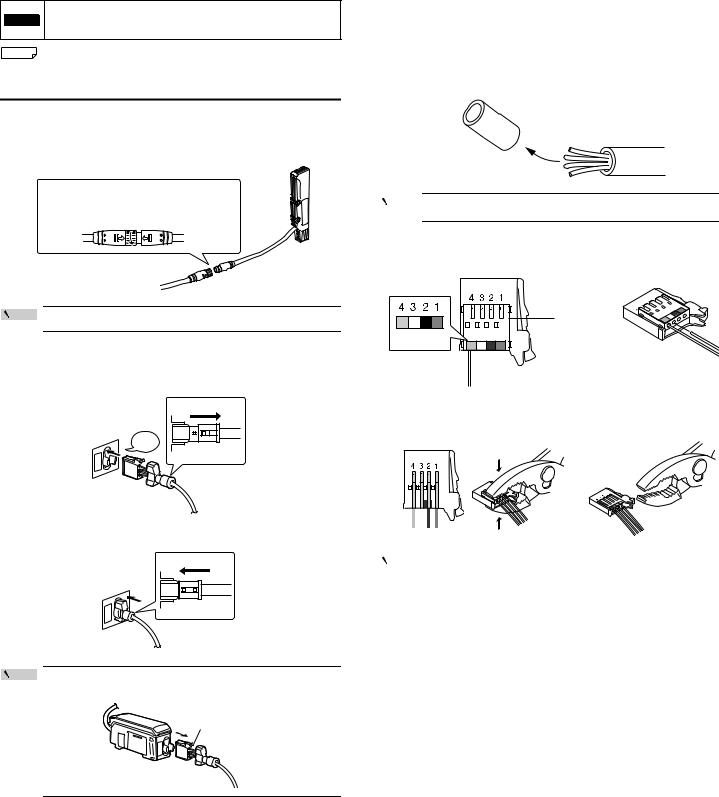
Connection and Wiring
Connecting the sensor head and amplifier
1 Attach the sensor head connection cables to the sensor head cable
(1) Align the arrow position of the connector to insert.
(2) Rotate the connector screw to tighten.
Point |
Tighten the connectors securely by hand. |
|
2 Attach the sensor head connection cable to the amplifier connector.
Remove the lock cover of the connector and insert it into the connectors of amplifier until a clicking sound is heard.
Lock cover
Click
Unlocked
3 Attach the lock cover to the connector to secure the cable.
Lock cover
Unlocked
Point |
When removing the sensor head connection cable, push in the |
|
|
|
lock lever and pull it out. |
|
Lock lever |
Attaching the sensor head cable connector (OP-84338: optional accessory)
Cut the sensor head connection cable to the required length and attach the new connector to use the sensor.
1 Cut the cable to the required length and strip approx. 15 mm of insulation from the end of the cable.
Point |
Do not strip the core wire insulation. |
|
2 Insert the wires into the connector holes of the matching color.
The cables should be inserted to the end and held in place.
|
Insert the |
|
Blue Black |
wires beyond |
|
this point |
||
White Brown |
||
|
3 Confirm that all wires are inserted to the specified position and crimp them using pliers or a similar tool.
|
|
|
|
|
|
|
|
|
|
|
|
|
|
|
|
|
|
|
|
|
|
|
|
|
|
|
|
|
|
|
|
|
|
|
|
|
|
|
|
|
|
|
|
|
|
|
|
|
|
|
|
|
|
|
|
|
|
|
|
|
|
|
|
|
|
|
|
|
|
|
|
|
|
|
|
|
|
|
|
|
|
|
|
|
|
|
|
|
|
|
|
|
|
|
|
|
|
|
|
|
|
|
|
|
|
|
|
Point |
|
|
After the connector is changed, connect it to the amplifier and |
||||||||
|
|
||||||||||
|
|
|
|
confirm normal operation. |
|||||||
|
|
|
|
If it does not operate normally, crimp the connector again with |
|||||||
|
|
|
|
pliers. |
|||||||
|
|
|
|
Once the connector is crimped, it cannot be reused. |
|||||||
|
|
|
|
|
|
|
|
|
|
|
|
E SK-1000 IM |
6 |
3. Basic Operations
This chapter describes basic operations and settings for the SK Series.
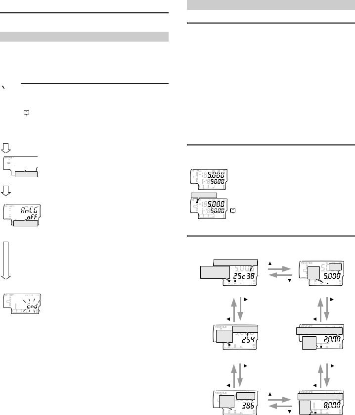
Operation When the Power is Turned on for the First Time
When the amplifier is turned on for the first time after the sensor head is connected, the initial setting screen appears after a few seconds. Adjust the initial settings according to the following procedure.
The initial setting is necessary for both the main unit and the expansion units when they are added.
|
Point |
|
Once the initial setting is completed, the initial setting display will |
||
|
|
|
not appear when the power is turned on the second time or |
||
|
|
|
thereafter. |
||
|
|
|
To change these settings, perform an initial reset. |
||
|
|
|
|
|
"Initial Reset (Initialize)" (page 8) |
|
|
|
|
||
|
|
|
|
|
|
|
|
|
|||
|
Power ON |
|
|||
|
|
|
|
|
|
HOLD  CALC
CALC CHECK
CHECK
LASER |
|
HI |
|
GO |
|
LO BANK
ALIGNMENT 01
2
3
R.V.
HI  Output polarity
[MODE] button
V |
kV ALARM |
HOLD 
 HI
HI 
 GO
GO
LO 
 BANK 0
 1
1 2
2
Analog output

[MODE] button
1 Press S / T button to select the polarity of judgment output and alarm output, and then press [MODE] button.
Setting value |
Description |
npn |
NPN output |
|
|
pnp |
PNP output |
2 Press S / T button to select the type of analog output and press [MODE] button. (For SK-1000 only)
Setting value |
Description |
|
off |
Not output |
|
|
|
|
0-5u |
Analog output after the judgment value (P.V.) is |
|
converted to the range from 0 to 5 V. |
||
|
||
-5-5u |
Analog output after the judgment value (P.V.) is |
|
converted to the range from -5 to 5 V. |
||
|
|
|
1-5u |
Analog output after the judgment value (P.V.) is |
|
converted to the range from 1 to 5 V. |
||
|
||
|
|
|
aMpr |
Analog output after the judgment value (P.V.) is |
|
converted to the range from 4 to 20 mA. |
||
|
HI |
V |
kV ALARM |
3 |
After the setting is complete, [end] blinks |
HOLD |
|
|||
LO |
BANK 0 |
|
|
several times on the sub display and the main |
GO |
|
|
|
|
|
1 |
ZERO SHIFT |
|
screen appears. |
|
TEMP %RH |
|
||
|
2 |
|
|
|
|
3 |
|
|
|
|
HI LO R.V. |
TIMING |
|
|
4 Change other settings as necessary.
Operations on the Main Screens
R.V. (Internal Measurement Value) and P.V. (Judgment Value)
This section describes R.V. (Internal Measurement Value) displayed on the sub display (lower level) and P.V. (Judgment Value) displayed on the main display (upper level).
R.V. (Internal Measurement Value)
R.V. (Internal Measurement Value) is the value displayed when a target is inserted into the measurement range. Only the charge potential can be displayed.
* R.V. = Raw Value
P.V. (Judgment Value)
P.V. (Judgment Value) is the value to set the judgment output to ON/OFF according to the tolerance setting value. Also, the analog output is output based on the P.V.. Only the charge potential can be displayed.
* P.V. = Present Value
 "Changing the Tolerance Values" (page 9)
The Judgment value (P.V.) and the Internal Measurement Value (R.V.) are typically the same value. However, when the hold function, step-count filter, or the calculation function is used, they will become different values.
 "6. Hold Function" (page 12)
* The R.V. and P.V. cannot be displayed for the temperature and humidity.
Main Display (Upper Level)
The judgment value (P.V.) is shown on the main display.
The display varies according to the functions used such as Normal, Hold function, and the Calculation function.
|
V |
kV ALARM |
Normal |
HOLD |
|
|
The same value as the internal measurement value (R.V.) is |
HI |
|
|
|
GO |
|
|
|
LO BANK 0 |
|
|
displayed as a judgment value (P.V.). |
3 |
|
|
|
1 |
|
|
|
2 |
|
|
|
TEMP |
%RH |
ZERO SHIFT |
|
HI |
LO R.V. |
TIMING |
|
[HOLD] ON |
|
When the hold function is used |
|||
HOLD |
|
V |
kV ALARM |
The judgment value (P.V.) is held according to the hold |
|
GO |
|
|
|
function settings. |
|
HI |
|
|
|
|
"6. Hold Function" (page 12) |
LO |
3 |
|
|
|
|
BANK 0 |
|
|
|
|
|
|
1 |
|
|
|
|
|
2 |
|
|
|
|
|
TEMP |
%RH |
ZERO SHIFT |
|
|
|
HI |
LO R.V. |
TIMING |
|
|
Sub Display (Lower Level)
The sub display can be switched with the arrow buttons W / X Depending on the type of displayed value, the sub display indicator [R.V. / TEMP / %RH / HI / LO] lights up.
Temperature/Humidity |
GO HI |
V |
kV ALARM |
||
TEMP][ RH] |
|
|
R.V. |
R.V. |
|
|
|
|
HOLD |
|
|
ON |
|
|
LO |
|
|
|
|
ON |
|
||
TEMP |
%RH |
ZERO SHIFT |
|
|
ZERO SHIFT |
HI |
LO R.V. |
TIMING |
|
HI LO R.V. |
TIMING |
(1) Temperature/humidity display screen |
(6) R.V. display screen |
||||
|
Temperature |
|
V |
kV ALARM |
|
HOLD |
LO side setting value |
||||
TEMP |
|
||||
ON |
|
|
LO |
|
|
TEMP |
%RH |
ZERO SHIFT |
ON |
%RH |
ZERO SHIFT |
HI |
LO R.V. |
TIMING |
LO R.V. |
TIMING |
|
(2) Temperature display screen |
(5) LO side setting value screen |
||||
|
|
Humidity |
|
|
V |
kV ALARM |
|
HI |
|
HI side setting value |
|||||
HOLD |
|
|
|
||||
GO RH |
|
|
|||||
ON |
|
|
|
|
2 |
|
|
|
|
|
|
|
0 |
|
|
|
|
|
|
HI 3 |
|
|
|
|
|
|
|
|
1 |
|
|
TEMP |
%RH |
|
ZERO SHIFT |
ON |
TEMP |
%RH |
ZERO SHIFT |
HI |
LO |
R.V. |
TIMING |
HI |
LO R.V. |
TIMING |
|
(3) Humidity display screen |
(4) HI side setting value screen |
||||||
(1) Temperature/humidity display screen
The temperature and humidity detected by the sensor head are displayed.
(2)Temperature display screen
The temperature detected by the sensor head is displayed.
(3)Humidity display screen
The humidity detected by the sensor head is displayed.
(4)HI side setting value screen
The upper limit of the acceptable range (tolerance setting value) for the target is displayed. This setting value can be changed. If the judgment value (P.V.) exceeds the value set here, the HI judgment output turns on.
 "Changing the Tolerance Values" (page 9)
7 |
E SK-1000 IM |
(5)LO side setting value screen
The lower limit of the acceptable range (tolerance setting value) for the target is displayed. This setting value can be changed. If the judgment value (P.V.) falls below the value set here, the LO judgment output turns on.
 "Changing the Tolerance Values" (page 9)
(6)R.V. display screen
The internal measurement value (R.V.) is displayed. The displayed value is not held even if a hold function is enabled.
Setting Operations
This section explains the functions of the main screen and the functions of each setting screen.
Functions Operable on the Main Screen
Main screen
|
|
V |
kV ALARM |
HOLD |
|
|
|
HI |
|
|
|
GO |
|
|
|
LO BANK 0 |
|
|
|
1 |
|
|
|
2 |
|
|
|
3 |
|
|
|
TEMP |
%RH |
|
ZERO SHIFT |
HI |
LO |
R.V. |
TIMING |
|
|
|
V |
kV ALARM |
|
HOLD |
|
|
|
|
SELECT |
HI |
|
|
|
|
|
GO |
|
|
|
|
|
LO |
BANK 0 |
|
|
|
|
|
|
|
SET |
MODE |
|
|
1 |
|
|
||
|
2 |
|
|
|
|
|
3 |
|
|
|
|
|
TEMP |
%RH |
|
ZERO SHIFT |
|
ZERO SHIFT |
HI |
LO |
R.V. |
TIMING |
SK-1000 |
|
|
|
|
Buttons used
Press W or X button.
Switching the sub display (lower level; page 7)
The internal measurement value (R.V.), HI side setting value, LO side setting value, temperature and humidity, temperature, or humidity is displayed, and the settings can be changed.
"Changing the Tolerance Values" (page 9)
Set the HI side tolerance setting value and the LO side tolerance setting value. The value is judged as HI, GO, or LO and is displayed and output.


 While pressing down [MODE], press S or T button.
"Bank Function (Registering Multiple
Tolerance Setting Values)" (page 9)
The HI side setting value, LO side setting value, and shift target value can be saved in up to four different banks, and the bank can be switched.
Press [MODE] and S buttons for approx. 2 seconds.
or
Press [MODE] and S buttons for approx. 2 seconds.
"Key Lock Function" (page 10)
This function prevents unwanted button operations during measurement.
Available Functions from the Main Screen
Main screen
|
|
V |
kV ALARM |
HOLD |
|
|
|
HI |
|
|
|
GO |
|
|
|
LO BANK 0 |
|
|
|
1 |
|
|
|
2 |
|
|
|
3 |
|
|
|
TEMP |
%RH |
|
ZERO SHIFT |
HI |
LO |
R.V. |
TIMING |

 Press [MODE] button for approx. 2 seconds.
"Basic Settings and Advanced Settings" (page 10)
Basic settings
Configure basic settings such as the measurement mode and the averaging rate.
Advanced settings
Configure more advanced settings such as the hold function and the timing input in order to use the unit in a wider range of applications.
While pressing the [MODE] button, press the [SET] button 5 times.
"Initial Reset (Initialize)" (page 8)
All settings, excluding the calibration function, are initialized.
[While pressing the [MODE] button, press the W button 5 times.
"Simulation Mode" (page 17)
You can use this function to check that the I/O wires for control have been wired correctly.
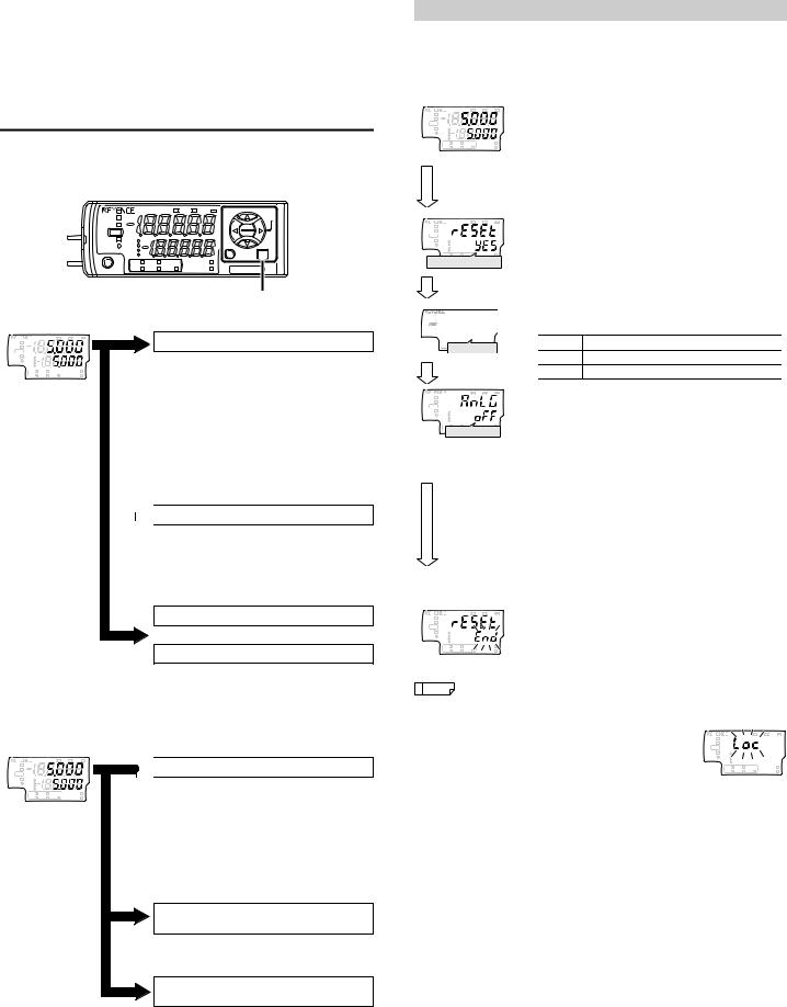
Initial Reset (Initialize)
When an initial reset is performed, all settings, excluding the calibration function, are initialized.
The judgment output's polarity and analog output setting can also be changed through the same operation.
Main screen
|
|
V |
kV ALARM |
HOLD |
|
|
|
HI |
|
|
|
GO |
|
|
|
LO |
BANK 0 |
|
|
|
1 |
|
|
|
2 |
|
|
|
3 |
|
|
|
TEMP |
%RH |
ZERO SHIFT |
|
HI |
LO R.V. |
TIMING |
|
While pressing |
||
|
the [MODE] |
||
|
button, press the |
||
|
[SET] button 5 |
||
|
times. |
|
|
|
|
V |
kV ALARM |
HOLD |
|
|
|
HI |
|
|
|
GO |
|
|
|
LO |
BANK 0 |
|
|
|
1 |
|
|
|
2 |
|
|
|
3 |
|
|
|
TEMP |
%RH |
ZERO SHIFT |
HI LO R.V. TIMING
Performing the initial reset
[MODE] button
HOLD  CALC
CALC CHECK
CHECK
LASER |
|
HI |
|
GO |
|
LO BANK
ALIGNMENT 01
2
3
R.V.
HI  Output polarity
[MODE] button
V |
kV ALARM |
HOLD |
|
HI |
|
GO |
|
LO BANK 0 |
|
1 |
|
2 |
|
3 |
|
TEMP %RH |
ZERO SHIFT |
HIAnalogLO R.V. 
 outputTIMING
1 While pressing the [MODE] button on the main screen, press the [SET] button 5 times.
[reset] is displayed on the main display (upper level).
2 Press S / T button to select [yes] and press the [MODE] button.
If [no] is selected at this point, only the output polarity and analog output settings can be changed without performing the initial reset.
3 Press S / T button to select the output polarity and press the [MODE] button.
Setting value |
Description |
|
|
npn NPN output
pnp PNP output
4 Press S / T button to select the analog output and press the [MODE] button. (For SK-1000 only)
[MODE] button
|
|
V |
kV ALARM |
HOLD |
|
|
|
HI |
|
|
|
GO |
|
|
|
LO BANK 0 |
|
|
|
1 |
|
|
|
2 |
|
|
|
3 |
|
|
|
TEMP |
%RH |
|
ZERO SHIFT |
HI |
LO |
R.V. |
TIMING |
Setting value |
Description |
|
off |
Not output |
|
|
|
|
0-5u |
Analog output after the judgment value (P.V.) is |
|
converted to the range from 0 to 5 V. |
||
|
||
|
|
|
-5-5u |
Analog output after the judgment value (P.V.) is |
|
converted to the range from -5 to 5 V. |
||
1-5u |
Analog output after the judgment value (P.V.) is |
|
converted to the range from 1 to 5 V. |
||
|
||
|
|
|
aMpr |
Analog output after the judgment value (P.V.) is |
|
converted to the range from 4 to 20 mA. |
||
|
||
|
|
 "9. Analog output scaling" (page 14)
5 After the initialization is complete, [end] blinks several times on the sub display and the main screen is restored.
|
Reference |
• When buttons other than the S / T button and [MODE] button are |
|||
|
|||||
|
|
pressed during the initial reset procedure, the initial reset is |
|
||
|
|
canceled and the screen in step 2 is restored. |
|
|
|
|
|
• When you attempt to initialize the unit while |
|
V |
kV ALARM |
|
|
the key lock function is set, the screen shown |
|
||
|
|
HOLD |
|
|
|
|
|
HI |
|
|
|
|
|
on the right appears and the initialization fails. |
GO |
|
|
|
|
LO BANK 0 |
|
|
|
|
|
1 |
|
|
|
|
|
Cancel the key lock before attempting to |
2 |
|
|
|
|
3 |
|
|
|
|
|
TEMP |
%RH |
ZERO SHIFT |
|
|
|
HI |
LO R.V. |
TIMING |
|
initialize the unit.
 "Key Lock Function" (page 10)
E SK-1000 IM |
8 |
Loading...