


 Loading...
96M00282
Ultra High-speed Sheath Sensing Ionizer
SJ-H(A)(V)(C) Series
SJ-H036*/060*/084*/108*/132*/156*/180*/204*/228*/252*/300*
Instruction Manual
Read this instruction manual before using the product in order to achieve maximum performance. Keep this instruction manual in a safe place after reading it so that it can be used at any time.
Symbols
The following symbols alert you to important messages. Be sure to read these messages carefully.
 Danger Failure to follow instructions may lead to death or serious injury.
 Warning • To avoid the risk of electric shock and ensure proper static elimination, be sure to completely ground the SJ-H* Series' 10-pin I/O cable.
•To avoid the risk of electric shock or product malfunctions, prevent water, oil, or flammable solvent from splashing onto the SJ-H* Series.
•To avoid the risk of electric shock or product malfunctions, keep fingers and metallic objects such as tools or wires away from the SJ-H* Series during operation.
•When the SJ-H* Series is used in an enclosed space, the generated ozone may become harmful.
Make sure that there is adequate ventilation when using the SJ-H* Series in an enclosed space.
•Do not use the SJ-H* Series in a location in which the temperature changes suddenly, or where condensation occurs. This may lead to an accident or product breakdown.
•To avoid the risk of electric shock, do not operate the SJ-H* Series with wet hands.
•To avoid the risk of electric shock or product malfunctions, be sure to turn the power off during maintenance of the SJ-H* Series.
•To avoid the risk of injury, do not touch the electrode probes directly with your hands or fingers during maintenance.
•If any abnormality is observed in the SJ-H* Series, immediately turn off the power and contact the nearest KEYENCE office. Do not try to repair the SJ-H* Series by yourself. This may cause electric shock or product malfunctions.
 Caution • Do not touch the SJ-H* Series' electrode probes with hard objects such as tools. If the electrode probes are damaged, the SJ-H* Series does not operate properly, resulting in product malfunctions.
•Operate the control panel of the SJ-H* Series with the flat-blade screwdriver provided with the product.
•When mounting the SJ-H* Series, use the provided End units (L/R) and Auxiliary Support Part, otherwise product malfunctions may result.
•When the SJ-H* Series is used over a long time, dust accumulates on the electrode probes. Clean the electrode probes when the alarm indicator flashes. If you continue to use the SJ-H* Series with dust accumulating on the electrode probes, the SJ-H* Series will not operate properly, resulting in product malfunctions. Regular cleaning (about every 2 weeks) is recommended.
•Do not drop the SJ-H* Series or subject it to a strong impact. This may cause product malfunctions.
•Do not use the SJ-H* Series for any purpose other than eliminating static electricity.
•When the SJ-H* Series is used in combination with other instruments, functions and performance maybe degraded, depending on operating conditions and the surrounding environment.
Precautions for power supply
Warning |
Failure to follow instructions may lead to injury. |
|
||
|
|
Caution |
• Use a DC power supply at a rated supply voltage of 24 to 36 V. |
|
|
|
|
• Noise conveyed through the power supply line may cause the SJ-H* Series to malfunction. |
|
Caution |
Failure to follow instructions may lead to product damage (product malfunctions, etc.). |
Be sure to use a stabilized DC power supply with an insulated transformer. |
||
• When using a commercially available switching regulator, be sure to completely ground |
||||
|
|
|
switching regulator's frame ground terminal. |
|
Important |
|
|
• Do not connect a number of power supplies to a single SJ-H* unit or more than one SJ-H* |
|
Provides important precautions and restrictions on proper operation. |
unit connected together, otherwise the power supplies will be short-circuited and product |
|||
|
||||
|
|
|
malfunctions may result. |
|
NOTE |
Provides additional information on proper operation. |
|
||
|
|
|||
Precautions for grounding
The 10-pin I/O cable for the SJ-H* Series is provided with a ground wire.
Reference  Provides useful information on proper operation.
 Provides reference pages.
Indicates that the operation is done on the SJ-H01 Remote Control Console for the SJ-H* Series.
 Caution • For proper static elimination, be sure to completely ground the SJ-H* Series' grounding cable.
• The grounding cable must be grounded at a resistance not exceeding 100 Ω.
Safety Precautions
General precautions
 Danger • You must verify that the SJ-H* Series are operating correctly in terms of functionality and performance before the start and the operation of the SJ-H* series.
•We recommend that you take substantial safety measures to avoid any damage in the event of a problem occurring.
•KEYENCE never warrant the function or performance of the SJ-H* Series if it is used in a manner that differs from the SJ-H* Series specifications contained in this instruction manual or if the SJ-H* Series are modified by yourself.
•Do not use the SJ-H* Series for the purpose of protecting the human body.
Warnings and cautions specific to the SJ-H* Series
The SJ-H* Series is a high-voltage device that is not designed to be explosion proof. Before using the SJ-H* Series, be sure to read the following warnings and precautions carefully.
Warning labels on SJ-H* Series
For safety reasons, the warning labels are attached to the SJ-H* Series. Read each label carefully and follow the instructions on the labels.
Locations
 Caution
To prevent product malfunctions, avoid installing the SJ-H* Series in the following locations.
•Locations in which the SJ-H* Series may be directly subjected to vibration or impact.
•Locations in which the ambient temperature drops below 0°C or exceeds + 40°C.
•Locations in which the relative humidity drops below 35% or exceeds 85%, or where condensation occurs.
•Locations in which the temperature changes suddenly.
•Locations in which the SJ-H* Series is exposed to a direct breeze from an air conditioner.
•Locations in which there are volatile, flammable substances or corrosive gas.
•Locations exposed to dust, salt, metal particles, or greasy fumes.
•Locations in which water, oil or chemicals may splash onto the SJ-H* Series.
•Locations in which a strong magnetic or electric field is generated.
•Locations where the altitude exceeds 2000 m.
•Outdoors
 Danger • Filling a closed space with nitrogen will reduce the oxygen levels in the air to dangerous levels.
Make sure that there is adequate ventilation when using the SJ-H* Series in an enclosed space.
• Do not use the SJ-H* Series in the presence of flammable or explosive gases or elements.
1
Other precautions
 Caution • Follow the warning instructions and cautions specified in this instruction manual.
•The SJ-H* Series uses an EEPROM. Do not turn off the unit while settings are made in the SJ-H* Series.
Precautions for CSA Certificate
The SJ-H* Series complies with the following CSA and UL standards, and has been certified by CSA.
CAN/CSA-C22.2 No.61010-1
Safety Requirements for Electrical Equipment for Measurement, Control, and Laboratory Use
UL61010-1
Safety Requirements for Electrical Equipment for Measurement, Control, and Laboratory Use
<Precautions>
•When selecting a power supply for use with the SJ-H* Series, always use a CSA/UL-listed power supply that either provides Class 2 output as defined in the Canadian Electrical Code/National Electrical Code, or that has been evaluated as a Limited Power Source as defined in CAN/ CSA-C22.2 No. 60950-1/UL60950-1.
•Always establish a proper ground connections when installing the SJ-H* Series.
•Use only the cables provided by KEYENCE (power cables and connector cables) to connect SJ-H* Series units to one another or to their power supplies.
•Install the SJ-H* Series in accordance with the installation and wiring instructions described in this instruction manual. Never operate the SJ-H* Series with the ratings that does not conform to the specifications described in this instruction manual.
* Seven units can be connected only when the 36 V power supply is used.
Please contact the nearest KEYENCE office when the 24 V power supply is used.
Precautions for CE Marking
The SJ-H* Series complies with the following EU Directives and EN standards. EU Directives
•EMC Directives (2004/108/EC)
•Low-voltage Directive (2006/95/EC)
EN Standards
•EN61326-1 Class A
•EN61010-1
<Precautions>
•Be sure to completely ground the SJ-H* Series' ground terminal when installing the SJ-H* Series.
•Overvoltage Category (Installation Category): I
•Pollution Degree: 2
•When selecting a power supply for use with the SJ-H* Series, always use a power supply that has been certified by a EU Notified Body (as a Limited Power Source as defined in EN60950).
•Use only the cables provided by KEYENCE (power cables and connector cables) to connect SJ-H* Series units to one another or to their power supplies.
•Install the SJ-H* Series in accordance with the installation and wiring instructions described in this instruction manual.Never operate the SJ-H* Series with the ratings that does not conform to the specifications described in this instruction manual.
* Seven units can be connected only when the 36 V power supply is used.
Please contact the nearest KEYENCE office when the 24 V power supply is used.
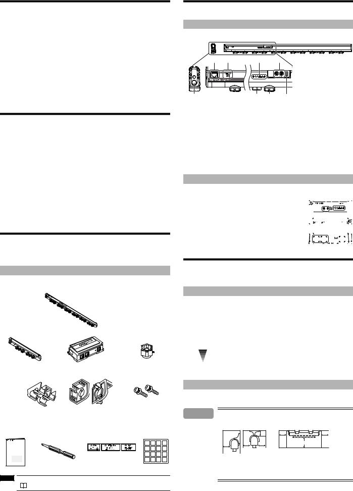
Checking the Package Contents
The package of SJ-H* Series includes the following items. Ensure that these items are included in your package before using the Unit. Extension cables and electrode probes for replacement are available as options.
 See "List of Optional Accessories" (page 9).
Contents
SJ-H060*/084*/108*/132*/156*/180*/204*/228*/252*/300* Controller-built-in Static Eliminator
SJ-H036* Static Elimination Bar |
SJ-H036* Controller |
Electrode probe |
|
|
replacement kit |
Auxiliary Support Part |
End Units (L/R) |
End Unit Securing Screws: 2 |
SJ-H036* : 0
SJ-H060* : 0
SJ-H084* : 0
SJ-H108* : 0
SJ-H132* : 1
SJ-H156* : 1
SJ-H180* : 1
SJ-H204* : 1
SJ-H228* : 2
SJ-H252* : 2
SJ-H300* : 2
Instruction Manual |
Flat-blade screwdriver |
The CAUTION/WARNING labels in |
ID number seal*1 |
|||
|
|
Japanese, German, French, Italian, |
|
|
|
|
|
|
and Chinese*1 |
0 |
1 |
2 |
3 |
|
|
|
||||
SJ-H(A)(V)(C) Series |
|
|
4 |
5 |
6 |
7 |
Instruction Manual |
|
|
|
|
|
|
|
|
|
8 |
9 |
10 |
11 |
|
|
|
12 |
13 |
14 |
15 |
*1 Use these language warning labels and ID number seals as needed.
NOTE |
The cables are sold separately. |
|
|
|
See "Cables" (page 3). |
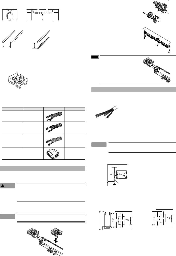
Part Names
This section lists the part names of the SJ-H* Series. For details about the operation keys and indicators on the controller's front panel, see "Names and functions of operation keys, switches, and indicators".
Static elimination bar (Control panel)
4 |
5 |
|
3 |
1 |
8 |
|
7 |
6 |
2 |
* The figure is for the SJ-H084*/108*/132*/156*/180*/204*/228*/252*/300*. The position of Ion monitor of SJ-H060* is different from other models.
The position of it is located to the right side of Remote control infrared receiver. SJ-H036* does not have 1 through 3 and 5.
1.Setting block (Not provided on SJ-H036*) (The ID switch is not provided on the SJ-HA Series)
2.Remote control infrared receiver (Not provided on the SJ-HA Series or SJ-H036*)
3.Indicator block (Not provided on SJ-H036*)
4.Cable connector (two on the SJ-H/HV/HC Series (except for SJ-H036*), and one on the SJ-HA Series and SJ-H036*)
5.Terminator switch (Not provided on the SJ-HA Series or SJ-H036*)
6.Electrode probe
7.Accelerating electrode probe (Not provided on the SJ-HA/HV/HC Series)
8.Air supply opening (Two on SJ-H036*/060*/084*/108*/132*/156*/180*/204*, and three on SJ-H228*/252*/300*)
Control panel (SJ-H036*)
1. |
Setting block (The ID switch is not provided on the SJ-H036A) |
1 2 |
|
|
3 |
|
|
|
|
||||||||
2. |
Remote control infrared receiver (Not provided on the SJ-H036A) |
|
|
|
|
|
|
|
|
|
|
|
|
|
|
|
|
3. |
Indicator block |
|
|
|
|
|
|
|
|
|
|
|
|
|
|
|
|
4. |
I/O Cable connector (Only one on the SJ-H036A) |
|
|
|
|
|
|
|
|
|
|
|
|
|
|
|
|
|
|
|
|
|
|
|
|
|
|
|
|
|
|
|
|||
5. |
Cable connector |
|
|
|
|
|
|
|
|
|
|
|
|
|
|
|
|
6. |
Terminator switch (Not provided on the SJ-H036A) |
|
|
|
|
|
|
|
|
|
|
|
|
|
|
|
|
|
|
|
|
|
|
|
|
|
|
|
|
|
|
|
|||
|
4 |
|
6 |
5 |
|
|
|||||||||||
|
|
|
|
|
|
|
|
|
|
|
|
|
|
|
|
|
|
|
|
|
|
|
|
|
|
|
|
|
|
|
|
|
|
|
|
|
|
|
|
|
|
|
|
|
|
|
|
|
|
|
|
|
|
|
|
|
|
|
|
|
|
|
|
|
|
|
|
|
|
|
|
|
|
|
|
|
|
|
|
|
|
|
|
|
|
|
|
|
|
Installation and Connection
This section explains how to set up and install the SJ-H* Series.
Before installation, carefully consider the operating conditions such as the distance between the static elimination bar and the target, or the time required for the elimination of the target's static charge.
Static elimination ability
Static elimination speed and operating distance
The SJ-H* Series offers a variety of frequency settings to enable flexible static elimination according to the location and application.
 See "Frequency setting" (page 4).
Static elmination speed |
Location |
Operating distance (mm) |
Recommended frequency (Hz) |
High-speed |
Production lines of films or sheets |
50-300 |
68, 47, 33, 22 |
|
(Short distance) |
||
|
|
|
|
|
|
|
|
|
Clean bench (Middle distance) |
300-1000 |
10, 8, 5 |
|
|
|
|
Low-speed |
On ceiling of clean room (Long distance) |
1000-2000 |
3, 1 |
|
|
|
|
Precautions for installation
Installation location
 Caution Refer to the following illustration to install the SJ-H* Series.
• Provide enough space between the static elimination bar and surrounding walls as shown in the figures below.
10 mm min.
|
|
10 mm |
10 mm |
|
|
min. |
min. |
|
|
|
20 mm min. |
10 mm |
10 mm |
10 mm |
|
min. |
min. |
|
|
min. |
|
|
|
•When mounting the SJ-H* Series, use the provided end unit and auxiliary support part, otherwise an accident or malfunction may result.
•Be sure that the cable stays more than 10 mm away from the SJ-H* Series, otherwise an accident or malfunction may result.
2
Interference
The SJ-H* Series may not operate properly if there is any conductive object close to the SJ-H* Series or if another SJ-H* unit is installed closely together. Refer to the following illustration and isolate the SJ-H* Series from the conductive object.
|
150 mm |
150 mm |
|
min. |
min. |
|
|
150 mm min. |
200 mm |
200 mm |
|
min. |
min. |
|
If two SJ-H* units are used, refer to the following illustration and separate the static elimination bars properly.
400 mm
min. 100 mm min.
Side-to -side installation |
Face-to-face installation |
Auxiliary support part (SJ-H132*/156*/180*/204*/228*/252*/300*)
Install the SJ-H132*/156*/180*/204*/228*/252*/300* with auxiliary support part. Auxiliary support part prevents the static elimination bar from bending. Do not install the SJ-H132*/156*/180*/204*/228*/ 252*/300* without using auxiliary support part.
Type |
No. of auxiliary support parts necessary |
|
for installation |
||
|
||
SJ-H036*/060*/084*/108* |
0 |
|
SJ-H132*/156*/180*/204* |
1 |
|
|
|
|
SJ-H228*/252*/300* |
2 |
|
|
|
Cables
The cables, including power cables and connector cables, required for the SJ-H* Series are not included in the package. Confirm the installation location before installing and make sure to buy the proper lengths of cables (10 pin I/O cable, 10-to-10-pin cable and 10-to-10-pin for SJ-H036* cables).
Item |
Type |
Appearance |
Description |
|
SJ-C2U |
|
Power cable for the SJ-H* |
|
|
Series. Three types (2-, 5-, |
|
10-pin I/O cable |
SJ-C5U |
|
|
|
10-m cables) are available. |
||
|
SJ-C10U |
|
|
|
|
(Cable color :Gray) |
|
|
|
|
|
|
|
|
Cable for connecting the |
|
OP-42210 |
|
SJ-H* Series units. Three |
|
|
types (2-, 5-, 10-m cables) |
|
10-to-10-pin cable |
OP-42211 |
|
|
|
are available. This cable |
||
|
OP-42212 |
|
|
|
|
connects to the Relay Box as |
|
|
|
|
|
|
|
|
well. (Cable color :Gray) |
|
|
|
The cable that connects the |
|
|
|
SJ-H036* controller to the |
10-to-10-pin cable |
SJ-C2H |
|
bar. Three types (2-, 5-, 10-m |
SJ-C5H |
|
cables) are available. 10-pin |
|
for SJ-H036* |
|
||
SJ-C10H |
|
I/O cable is necessary for |
|
|
|
||
|
|
|
supplying power. |
|
|
|
(cable color :Black) |
|
|
|
This is required if the cables |
Relay box |
OP-84296 |
|
will extend more than 10 |
for SJ-H* |
|
meters. (For use with the |
|
|
|
||
|
|
|
10-to-10-pin cable) |
Installing SJ-H* Series
Installing SJ-H* Series
Install the SJ-H* Series in places where a static problem occurs or may occur.
 Caution • When installing the SJ-H132*/156*/180*/204*/228*/252*/300*, mount and secure the auxiliary support parts with screws for the prevention of the static elimination bar from bending, otherwise the static elimination bar may be broken.
 See "Precautions for installation" (page 2).
•Keep a space of at least 10 mm around the static elimination bar after installation, otherwise the static elimination bar may malfunction or receive damage.
1Mount the auxiliary support parts on top of the static elimination bar or along the guide rails.
The SJ-H132*/156*/180*/204* requires a single auxiliary support part, the SJ-H228*/252*/300* requires two auxiliary support parts. Mount them at approximately equal intervals.
 Caution Confirm that the hooks on the auxiliary support part grasp the guide rails on the static elimination bar when installing.
• Mounting from the side |
• Mounting from the top |
2 Attach the end unit to each end of the static elimination bar.
3 Secure the SJ-H* Series with M4 screws at the desired installation position.
When installing the SJ-H132*/156*/180*/204*/ 228*/252*/300*, secure the auxiliary support part with M4 screws as well.
NOTE |
When removing the auxiliary support part, be sure to |
remove it from the side along the guide rails.
Wiring diagram (SJ-C2U/C5U/C10U 10-pin I/O cable)
Cord color |
Description |
Brown |
DC power supply (rated voltage of DC 24 to 36 V ±10 %) |
Brown/White |
[The ends are soldered together before shipping] |
|
|
|
|
Blue |
Power supply GND |
Blue/White |
[The ends are soldered together before shipping] |
|
|
|
|
Pink |
Static elimination interrupt input |
|
|
Orange |
Output signal GND |
Black |
Ion level alarm output |
|
|
White |
Condition alarm output |
|
|
Gray |
Alarm output |
Shield wire (thick black wire) |
Ground (Ground at a resistance not exceeding 100Ω.) |
*The blue wire and orange wire are insulated from each other.
*Be sure install both of the brown and brown/white wires and blue and blue/white wires.
 Caution Do not short-circuit the output signal wire and output signal GND wire together without any load, otherwise the internal circuit will be damaged, which may result in product malfunctions, because the SJ-H* Series does not have any overcurrent protection circuit.
Input circuit
[Pink (Static Elimination Interrupt Input)]
|
VCC (Power supply) |
INPUT (Pink) |
2.7 kΩ |
|
|
0V (Blue) |
2.4 kΩ |
Apply NPN open collector input to the INPUT and 0 V terminals from non-voltage contacts (such as relays).
Output circuit
Photo Relay Output [Gray (Alarm Output)]
Output GND
ALM_B
A
B
A
Output GND ALM_A B
Photo Relay Output
[Black (Ion Level Alarm Output),
White (Condition Alarm Output)]
OUT DC40 V
 100 mA
Output GND
3

Connection of power supply
Connecting SJ-H060*/084*/108*/132*/156*/180*/204*/228*/252*/300* to power supply
A 10-pin I/O cable (sold separately) is required to connect the SJ-H060*/084*/108*/132*/156*/180*/ 204*/228*/252*/300* to power supply.
 See "Terminator switch setting" (page 6).
1 See "Wiring diagram" (page 3) and connect each wire of the 10-pin I/O cable.
 Caution • For proper static elimination, the ground wire must be grounded at a resistance not exceeding 100Ω.
•Use a DC power supply with a marginal output (at least 500 mA) at a rated voltage of 24 to 36 V.
•Do not connect a number of power supplies to a single SJ-H* unit or more than one SJ-H* unit connected together, otherwise the power supplies will be short-circuited an accident or malfunction may result.
2 Connect the modular connector of the 10-pin I/O cable to the SJ-H060*/084*/108*/132*/156*/180*/204*/228*/252*/300*.
A 10-pin cable connector each is provided to the front and back of the SJ-H060*/084*/108*/132*/156*/180*/204*/228*/ 252*/300*. (for the SJ-HA Series, it is provided only to the front) The connector will snap when it is connected correctly.
NOTE |
When connecting the SJ-H/HV/HC Series, set the termi- |
|
nator switch according to the cable connector to be used. |
|
If the terminator switch is not set correctly, alarm output |
|
will not output correctly. |
|
See "Terminator switch setting" (page 6). |
 Caution • Press the tab of the modular connector to disconnect the cable. Do not pull the cable without pressing the tab, otherwise the cable may be damaged.
•Keep a space of at least 10 mm around the static elimination bar after installation, otherwise the static elimination bar may malfunction or receive damage.
Connecting SJ-H036* to power supply
A 10-pin I/O cable and a 10-to-10-pin cable (both sold separately) are required to connect the SJ-H036* to power supply.
 See "Terminator switch setting" (page 6).
1 See "Wiring diagram" (page 3) and connect each wire of the 10-pin I/O cable.
 Caution • For proper static elimination, the ground wire must be grounded at a resistance not exceeding 100 Ω.
•Use a DC power supply with a marginal output (at least 500 mA) at a rated voltage of 24 to 36 V.
•Do not connect a number of power supplies to a single SJ-H* unit or more than one SJ-H* unit connected together, otherwise the power supplies will be short-circuited an accident or malfunction may result.
2 Connect the modular connector of the 10-pin I/O cable to the SJ-H036* controller.
The SJ-H036* controller has two 10-pin cable connectors indicated GRAY (the SJ-H036A only has one), either one of which can be used.
The connector will snap when it is connected correctly.
3 Connect the SJ-H036* controller and the static elimination bar over the 10-to-10-pin cable.
Connect the cable to the connector marked by the word "BLACK." Then connect the cable to the static elimination bar of the SJ-H036*.
The connector will snap when it is connected correctly.
NOTE |
When connecting the SJ-H/HV/HC Series, set the termi- |
|
|
|
nator switch according to the cable connector to be used. |
|
If the terminator switch is not set correctly, alarm output |
|
will not output correctly. |
|
See "Terminator switch setting" (page 6). |
 Caution • Press the tab of the modular connector to disconnect the cable. Do not pull the cable without pressing the tab, otherwise the cable may be damaged.
•Keep a space of at least 10 mm around the static elimination bar after installation, otherwise the static elimination bar may malfunction or receive damage.
NOTE |
The SJ-H036* static elimination bar and controller should bear the same serial number. Check that they |
|
|
|
bear the same serial number when connecting them. |
Static Elimination Setting
This section provides the name and functions of operation keys, switches, and indicators on the controller’s front panel. It also describes the operation procedure for the static elimination setting.
Names and functions of operation keys, switches, and indicators
The control panel of the SJ-H084*/108*/132*/156*/180*/204*/228*/252*/300* has the same layout. The control panel of the SJ-H060* and SJ-H036* has the setting switch and LED positions swapped.
3 5
4 |
1 |
2 |
1. ID switch............. |
Sets the ID number if the SJ-H* unit is used with another SJ-H* unit. (The SJ-HA |
|
Series does not have this switch) |
2.FREQ switch....... Sets the frequency
3.ION MONITOR ... Displays the strength of the electric charge of the object. If the SJ-H01 is used,
the quantity of ion generation will be displayed. 4. RC Control/Setting Indicator
........................... This flashes when the SJ-H* Series is being controlled via remote control, during Dual I.C.C. confirmation and when the L.P.C. function is in use. (This cannot be used on the SJ-HA Series)
5. Alarm Indicator... This flashes once per second if static elimination power is affected by situations such as an absorption of ions by surrounding metals, which can cause instability of the setting environment (temperature, humidity, surrounding metals).
(Condition alarm) This will blink twice per second if the ion generation capability falls below the set value due to wear or dirt on the electrode probe.
(Ion level alarm) Flashes if the quantity of ion generation is low due to the deterioration of the electrode probes or the dirt on the electrode probes. Then static elimination will be forcibly turned OFF. (Alarm)
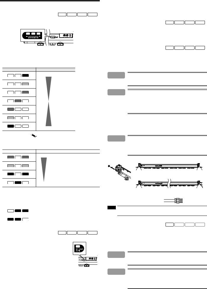
Frequency setting SJ-HSeries SJ-HASeries SJ-HVSeries SJ-HCSeries
A frequency is set with the FREQ switch in the SJ-H* Series.
When the frequency setting is made, the indicator for the present frequency on the ION MONITOR will flash for approximately five seconds. Then the indicator will be turned OFF.
Frequency |
FREQ. switch |
ION MONITOR |
||
68Hz |
0 |
|
|
|
|
|
OFF |
OFF |
Green |
47Hz |
1 |
|
|
|
|
|
OFF |
OFF |
Yellow |
33Hz |
2 |
|
|
|
|
|
OFF |
OFF |
Red |
22Hz |
3 |
|
|
|
|
|
OFF |
Green |
OFF |
10Hz |
4 |
|
|
|
|
|
OFF |
Yellow |
OFF |
8Hz |
5 |
|
|
|
|
|
OFF |
Red |
OFF |
5Hz |
6 |
|
|
|
|
|
Green |
OFF |
OFF |
3Hz |
7 |
|
|
|
|
|
Yellow |
OFF |
OFF |
1Hz |
8 |
|
|
|
|
|
Red |
OFF |
OFF |
For remote control console * |
9 |
|
|
|
* This cannot be used on the SJ-HA Series.
 For frequency settings in detail, see "Static elimination ability" (page 2).
4
Other Functions
This section describes other functions such as the display function, alarm output function, and air purge function.
Indicators |
SJ-HSeries SJ-HASeries SJ-HVSeries SJ-HCSeries |
The target's static charge and the quantity of ions generated from the static elimination bar are displayed on the ION MONITOR.
Electric charge indicator
The ION MONITOR works as an electric charge indicator that displays the target's static charge, polarity of the static charge, and condition of static elimination.
The plus and minus side LEDs will illuminate in response to the current charge level.
When static elimination is finished, the indicator in the middle will be illuminated. Therefore, the user will know the process of static elimination.
|
ION MONITOR |
Condition |
|
|
|
|
|
Positively charged object |
High |
|
|
|
|
|
OFF |
OFF |
Red |
|
|
|
|
|
|
Middle |
OFF |
OFF |
Yellow |
|
|
|
|
|
|
Low |
OFF |
OFF |
Green |
|
|
OFF |
Green |
OFF |
|
|
|
|
|
|
Low |
Green |
OFF |
OFF |
|
|
|
|
|
|
Middle |
Yellow |
OFF |
OFF |
|
|
|
|
|
|
High |
Red |
OFF |
OFF |
Negatively charged object |
|
|
|
|||
Ion quantity indicator 

The ION MONITOR works as an ion quantity indicator as well, and continuously monitors the quantity of ions generated from the static elimination bar and displays the measurement in the colors of the LED.
When leftmost and rightmost indicators are illuminated green, it means that on the SJ-H* Series is fully generating ions. * This cannot be used on the SJ-HA Series.
ION MONITOR |
Condition |
|
|
Large quantity of ion
Green OFF Green
Yellow OFF Yellow
Red OFF Red
OFF |
Red |
OFF |
Small quantity of ion |
|
When the SJ-H01 Remote Control Console is used to set continuous generation of positive (or negative) ions, only two indicators on the positive (or negative) side will be illuminated.
The ION MONITOR does not display the target's static charge or condition of static elimination. * This cannot be used on the SJ-HA Series.
|
|
ION MONITOR |
Condition |
|
|
|
|
|
Continuous positive ion generation |
|
OFF |
Red |
Red |
|
|
|
|
|
|
|
|
|
|
Continuous negative ion generation |
|
Red |
Red |
OFF |
|
|
|
|
|
|
Alarm output function |
SJ-HSeries SJ-HASeries SJ-HVSeries SJ-HCSeries |
|||
Alarm function (ALM)
The ION/ALM/COND indicator will flash red three times per second and an alarm signal (N.C. control signal) will be output if the internal circuit is damaged or an abnormal electrical discharge occurs.
Then the SJ-H* Series will stop generating ions.
Alarm output will activate regardless of whether or not static elimination is being interrupted manually or forcibly.
Ion level alarm function (ION)
The ION/ALM/COND indicator will flash twice per second and an alarm
signal (N.O. control signal) will be output if the quantity of ion generation is low due to the deterioration of the electrode probes or the dirt on the electrode probes. Static elimination will not be interrupted in this case. By using the SJ-H01 Remote Control Console, the warning output can be adjusted in four levels according to the quantity of ions generated. (The warning output cannot be adjusted on the SJ-HA Series).
The ion level warning can be a notice for the maintenance of the electromagnetic probes. Static elimination continues, so make sure to turn off the power when you perform maintenance on the electromagnetic probes.
Condition alarm function (COND)
The ION/ALM/COND indicator will flash once per second and an alarm signal (N.O. control signal) will be output if the installation environmental conditions (e.g., the temperature, humidity, and ambient metal) are unstable and likely to affect the performance of static elimination adversely (e.g., the absorption of ions) caused by ambient metal objects. Static elimination will not be interrupted in this case. By using the SJ-H01 Remote Control Console, the warning output can be adjusted in four levels according to the installation environment. (The warning output cannot be adjusted on the SJ-HA Series)
Elimination interruption function |
SJ-HSeries SJ-HASeries SJ-HVSeries SJ-HCSeries |
For the purpose of energy saving, by short-circuiting the blue (DC GND wire) and pink (static elimination interruption input signal wire) wire terminals of the 10-pin I/O cable, only the static elimination function will be turned OFF without turning off the SJ-H* Series.
Air-purge function |
SJ-HSeries SJ-HASeries SJ-HVSeries SJ-HCSeries |
Supplying clean air through the air duct on both ends of the static elimination bar will prevent the dust accumulation on the electrode probes. The air purge widens the static elimination area and increases the speed of static elimination as well.
*The air pressure indicates the pneumatic value at the route of the joint.
*Please contact the nearest KEYENCE office when using the air-purge function with intermittent air supply.
 Danger Filling a closed space with nitrogen will reduce the oxygen levels in the air to dangerous levels.
Make sure that there is adequate ventilation when using the SJ-H* Series in an enclosed space.
 Caution • Check that the air pressure does not exceed 0.5 MPa, otherwise an accident or malfunction may result.
•Please contact the nearest KEYENCE office when opening and closing the air duct.
•Be sure to provide clean, dry air to the static elimination bar. If the air contains water or oil, air leaks or electrical discharges may occur in the static elimination bar, thus resulting in accidents or malfunctions.
•Be sure to supply air from both sides (2 locations) of the SJ-H036*/060*/084*/108*/132*/ 156*/180*/204*.
•Be sure to supply air from both sides (3 locations) of the SJ-H228*/252*/300*.
Provide clean, dry air free of organic matter at a condensation point of -25 °C and approximately 0.01 μm in mesh size.
Air supply method
As shown in the illustration below, remove the screw that block the air duct on either end of the static elimination bar, connect a joint to the air duct, and provide air.
 Caution • Be sure to limit the tightening torque to 1.2 N•m (12 kg•cm2) or less. Otherwise, an accident or product breakdown may occur.
•Be sure to supply only clean, dry air. The use of improper air may cause an accident or product malfunctions.
•Be sure to supply air from both sides (2 locations) of the SJ-H036*/060*/084*/108*/132*/ 156*/180*/204*.
•Be sure to supply air from both sides (3 locations) of the SJ-H228*/252*/300*.
SJ-H036*/060*/084*/108*/132*/156*/180*/204*
R1/8 |
Rc1/8 |
Rc1/8 |
R1/8 |
SJ-H228*/252*/300* |
|
|
|
R1/8 |
Rc1/8 |
Rc1/8 |
R1/8 |
Recommended joint
The recommended joint is the Tube Fitting (tube diameter : φ 8 mm) manufactured by Pisco Co.
Tube diameter φ 8 mm : PC8-01
NOTE |
• Use a joint having a tube diameter of 8 mm on the SJ-H* Series. |
•When providing air to more than one SJ-H* unit, check that each static elimination bar is provided with air. If the air supply source is one, each static elimination bar may not be provided with enough air.
Air booster |
SJ-HSeries SJ-HASeries SJ-HVSeries SJ-HCSeries |
An optional air booster can be mounted to the SJ-H Series.
By using the air booster, the static elimination speed can be improved and the static elimination range can be expanded.
For more details, see the air booster Instruction Manual.
*The air booster cannot be used with SJ-HA/SJ-HV/SJ-HC Series.
*Please contact the nearest KEYENCE office when using the air-purge function with intermittent air supply.
 Danger Filling a closed space with nitrogen will reduce the oxygen levels in the air to dangerous levels.
Make sure that there is adequate ventilation when using the SJ-H* Series in an enclosed space.
 Caution • Check that the air pressure does not exceed 0.5 MPa, otherwise an accident or malfunction may result.
•Please contact the nearest KEYENCE office when opening and closing the air duct.
•Be sure to provide clean, dry air to the static elimination bar. If the air contains water or oil, air leaks or electrical discharges may occur in the static elimination bar, thus resulting in accidents or malfunctions.
•Be sure to supply air from both sides (2 locations) of the air booster.
Provide clean, dry air at a condensation point of -25 °C and approximately 0.01 μm in mesh size.
5
Loading...