


 Loading...
96M10750
High-speed, High-precision
Compact Static Elimination Blower
SJ-F100W/100/010
Instruction Manual
Before using this Compact Static Elimination Blower, be sure to thoroughly read this Instruction Manual.
After you are finished with this Instruction Manual, be sure to store it in a safe place for quick reference.
Preface
This document describes handling, method of operation and precautions when using the High-speed, High-precision Compact Static Elimination Blower Unit SJ-F100W/100/010. Before you start to use the SJ-F100W/100/010, be sure to thoroughly read this document in order to make full use and safely use the functions of the SJ-F100W/100/010.
Store this document in a safe place so that you can retrieve it whenever necessary.
Symbols
This manual uses the following symbols to alert you to important information.
Failure to follow these instructions may lead to death or serious injury.
DANGER
Failure to follow these instructions may lead to injury.
WARNING
CAUTION |
Failure to follow these instructions may lead to physical damage (product |
|
malfunction, etc.). |
||
|
Important Provides additional information on precautions and restrictions that must be followed in operation.
Note Provides additional information on proper operation.
Reference  Indicates useful information or information that aids understanding of text descriptions.
Indicates a reference item or page to be referred to in this manual and a separate manual.
Safety Precautions
General Precautions
•At startup and during operation, be sure to monitor the functions and performance of the SJ-F100W/100/010.
•We recommend that you take substantial safety measures to avoid any damage in the event that a problem occurs.
•Do not modify the SJ-F100W/100/010 or use it in any way other than described
|
in the specifications. The functions and performance of products used or |
|
CAUTION |
||
modified in this way cannot be assured. |
||
|
•When the SJ-F100W/100/010 is used in combination with other instruments, functions and performance may be degraded, depending on operating conditions and the surrounding environment.
•Do not use the SJ-F100W/100/010 for the purpose of protecting the human body.
SJ-F100W/100/010 Handling Precautions
The SJ-F100W/100/010 is a high-voltage product that is not designed in an explosionproof structure. Pay attention to the following when using the SJ-F100W/100/010.

 WARNING
•To prevent electric shock and to ensure accurate static elimination, be sure to connect a Class D earth (maximum resistance of 100 Ohms).
•Do not use this product in locations where there is the risk of ignition or explosion from flammable solvents or dirt and dust.
•High voltage is applied to this product. Prevent it from being splashed with water, oil, or flammable solvents. Failure to do so might cause insulation breakdown, which will result in electric shock or malfunction.
•Do not bring your fingers or tools, wire or other metallic objects near this product.
Doing so might cause electric shock or malfunction.
•Do not use this product in a non-ventilated location. The ozone generated
from this product may become toxic. Be sure to ventilate the installation site when this product is used in a non-ventilated location.
•Do not use this product in locations where sudden changes in temperature or condensation are likely to occur.
•Do not operate this product with wet hands. Doing so might cause electric shock.
•Before starting maintenance, be sure to turn the power OFF. Failure to do so might result in electric shock or malfunction.
•During maintenance, do not directly touch the electrode needles. Doing so might cause personal injury.
•If any malfunction is observed in this product, immediately turn it OFF, and contact your nearest agent. You should never repair this product yourself. Doing so might cause electric shock or malfunction.
Do not touch the electrode needles with a tool or other hard object. Damage to 
 CAUTION the electrode needles will prevent static elimination performance from being
fully demonstrated, and cause accidents or malfunction.
96M10750 |
i |
•When this product is used for a long period of time, the electrode needles become dirty due to the adhesion of dust and dirt. If the ion level alarm indicator or condition alarm indicator lights, clean the electrode needles. If the electrode needles are used in a dirty or dusty state, the static elimination
performance can no longer be fully demonstrated, resulting in accidents or 
 CAUTION malfunction. We recommend periodically cleaning the electrode needles (as a
guideline, once every two weeks in a regular operating environment though this depends on the installation conditions).
•Do not drop or subject this product to shock. Doing so might result in accident or malfunction.
•Use this product for static elimination only. Do not use it for other purposes.
Power Supply Precautions
•Use a DC power supply with rated 24 V output.
•Noise applied to the power supply may cause this product to malfunction. If
CAUTION |
this happens, install an insulated transformer. |
•When using a switching regulator, be sure to connect a Class D earth to the Frame Ground terminal.
Grounding Precautions
•To ensure safety and appropriate static elimination, be sure to ground this
CAUTION |
product. |
•Be sure to connect a Class D earth (maximum resistance of 100 Ohms)
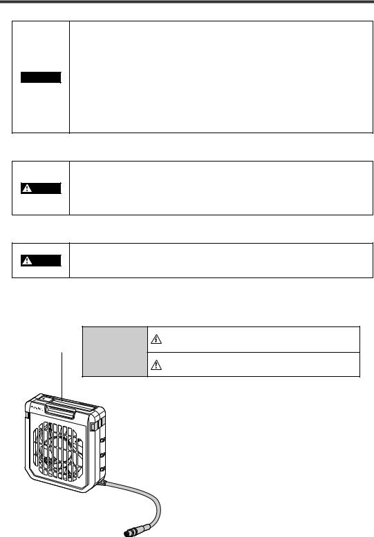
SJ-F100W/100/010 Warning Label
A WARNING label is affixed on the SJ-F100W/100/010 to ensure safety.
Read the description on this WARNING label to ensure correct use of the SJ-F100W/100/010.
Be sure to turn the power off when replacing

 WARNING
the electrode probes. Otherwise, electric shock may occur.
Do not touch electrode probes with your hands or fingers, as this may cause injury.
*WARNING labels in Japanese, German, French and Italian are provided. Use them as necessary.
SJ-F010
ii
Installation Precautions
Avoid installing the SJ-F100W/100/010 in the following locations as this may cause accidents.
•Locations directly subject to vibration and shock
•Locations subject to ambient temperature out of the 0°C to +50°C range
•Locations subject to ambient humidity out of the 35 to 65%RH range (condensation not allowed)
•Locations subject to sudden changes in temperature
CAUTION |
• Locations subject directly from blasts from air conditioners |
•Locations subject to voltatile or flammable substance, solvents or corrosive gases
•Locations subject to large amounts of dirt, and dust, salt, iron and oil smoke
•Locations that may be splashed with water, oil or chemical mist
•Locations where strong magnetic and electrical fields are generated
About Warming up the SJ-F100W/100/010
Note Leave the SJ-F100W/100/010 for about 20 minutes after turning the power ON to allow the ion balance to stabilize.
The ion balance may be unstable during this warming up period.
Other Precautions
•Be sure to read the WARNINGS and CAUTIONS described in each of the items
in this Instruction Manual.
CAUTION • The Static Elimination Blower Unit has a built-in EEPROM. Do not turn the
Static Elimination Blower Unit OFF during the setup.
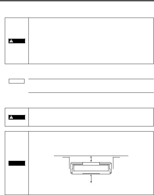
Refer to the following diagram when installing the SJ-F100W/100/010.
•Install the Static Elimination Blower Unit away from the wall or surrounding objects.
30 mm or more

 CAUTION
50 mm or more
•Install the Static Elimination Blower Unit so that the Electrode Unit can be removed for replacement.
iii

This page left intentionally blank
iv
How This Manual Is Organized
About the Static
1Elimination Blower Unit SJ-F100W/100/010
2 |
|
Connection and |
|
|
|
||
|
Installation |
|
|
|
|
|
|
3 |
|
SJ-F100W/100/010 |
|
|
Functions |
|
4Maintenance
5Specifications
This chapter describes the features of the Static Elimination Blower Unit SJ-F100W/100/010, and the names and functions of parts.
Appendices
1
2
3
4
5
v

Contents
Preface |
|
Safety Precautions .................................................................................................................... |
i |
How This Manual Is Organized ................................................................................................ |
v |
Contents ................................................................................................................................... |
vi |
Precautions on Regulations and Standards ....................................................................... |
viii |
Conventions Used In This Manual ......................................................................................... |
ix |
Page Configuration and Symbols ...................................................................................... |
ix |
Terminology ....................................................................................................................... |
ix |
Chapter 1 About the Static Elimination Blower Unit SJ-F100W/100/010
1-1 |
Features of the SJ-F100W/100/010 .............................................................................. |
1-1 |
|
Outline of the SJ-F100W/100/010 .............................................................................. |
1-1 |
1-2 |
Checking the Contents of the Package ...................................................................... |
1-3 |
|
Package Contents ...................................................................................................... |
1-3 |
|
Options ....................................................................................................................... |
1-3 |
1-3 |
Names and Functions of Parts .................................................................................... |
1-4 |
|
Static Elimination Blower Unit .................................................................................... |
1-4 |
|
Controller Unit (operation/display section) ................................................................. |
1-5 |
|
Controller Unit (I/O terminal section) .......................................................................... |
1-6 |
Chapter 2 Connection and Installation
2-1 |
Before Installation ........................................................................................................ |
2-1 |
|
About Static Elimination Performance ........................................................................ |
2-1 |
|
Installation Precautions .............................................................................................. |
2-3 |
2-2 |
Connection and Installation ........................................................................................ |
2-4 |
|
Installing the SJ-F100W/100/010 ............................................................................... |
2-4 |
|
Connecting Cables ..................................................................................................... |
2-6 |
Chapter 3 SJ-F100W/100/010 Functions
3-1 |
Fan Speed Adjustment Function ................................................................................ |
3-1 |
|
Fan Speed Adjustment Function ................................................................................ |
3-1 |
3-2 |
Ion Monitor Functions .................................................................................................. |
3-2 |
|
Ion Monitor Functions ................................................................................................. |
3-2 |
3-3 |
Alarm Output Functions .............................................................................................. |
3-3 |
|
Alarm Output Functions ............................................................................................. |
3-3 |
3-4 |
Other Functions ............................................................................................................ |
3-4 |
|
Abnormal Discharge Detection Function .................................................................... |
3-4 |
|
Ion Balance Adjustment Function .............................................................................. |
3-4 |
|
Static Elimination Stop Function ................................................................................ |
3-6 |
vi

Chapter 4 Maintenance
4-1 |
About Maintenance ...................................................................................................... |
4-1 |
|
About Maintenance .................................................................................................... |
4-1 |
4-2 |
Performing Maintenance on the Electrode Needles .................................................. |
4-2 |
|
Performing Maintenance on the Electrode Needles ................................................... |
4-2 |
Chapter 5 Specifications
5-1 |
Timing Charts ............................................................................................................... |
5-1 |
5-2 |
Specifications ............................................................................................................... |
5-3 |
5-3 |
External Dimensions .................................................................................................... |
5-4 |
Appendices
1 |
Troubleshooting ............................................................................................................... |
A-1 |
2 |
Table of Indicated States ................................................................................................. |
A-2 |
3 |
List of Options .................................................................................................................. |
A-7 |
4 |
Index .................................................................................................................................. |
A-8 |
vii

Precautions on Regulations and Standards
CE Marking
Keyence Corporation has confirmed that this product complies with the essential requirements of the applicable EC Directive, based on the following specifications.
Be sure to consider the following specifications when using this product in the Member State of European Union.
●EMC Directive (2004/108/EC)
•Applicable standard: EN61326-1
•Be sure to provide a ground when installing the SJ-F100W/100/010.
•The length of cable (power lead and I/O leads) must be less than or equal to 30 m.
Remarks:
These specifications do not give any guarantee that the end-product with this product incorporated complies with the essential requirements of EMC Directive. The manufacturer of the end-product is solely responsible for the compliance on the end-product itself according to EMC Directive.
●Low-Voltage Directive (2006/95/EC)
•Applicable standard: EN61010-1
• Overvoltage category I
•Use this product under pollution degree 2.
•Use the power supply for the SJ-F100W/100/010, that satisfies the requirements of the Limited Power Source specifications stipulated in EN60950-1 and certified by European third-party certification organization, or a Keyence Corporation AC adapter (SJ-U2). The specifications of the AC adapter (SJ-U2) are as follows.
When connecting to an SJ-U2, be sure to use a power cable compliant with European standards. Applicable standard: EN60950-1
Overvoltage category |
II |
Pollution degree |
2 |
• Be sure to provide a ground when installing the SJ-F100W/100/010.
viii
Conventions Used In This Manual
The following shows how pages are configured, and the symbols and terminology used in this manual.
Page Configuration and Symbols
Thumbnail index Indicates the chapter.
Chapter title
Operational step
Warning
The user may be subjected to physical harm (electric shock, burns, etc.) if he does not observe the particulars described here.
Note:
Describes cautions for easily mistaken operations. Be sure to read these.
Caution
Failure to observe the caution described here may result in product trouble.
2-2 Connection and Installation
This section describes how to connect and install the Static Elimination Blower Unit and Controller Unit.
Installing the SJ-F100W/100/010
2
Connection |
Install the SJ-F100W/100/010 at locations where static electricity is generated or is likely to be |
generated. |

 Installing the Static Elimination Blower Unit
There are two ways of installing the Static Elimination Blower Unit, with or without the mounting fixtures.
and |
When using mounting fixture A: |
|
|
|
Installation |
|
|
||
mounting fixture A (OP-51409) with the M4 screws. |
|
|||
|
1 Tap M4 screw holes where the Static Elimination Blower Unit is to be installed, and fasten |
|||
|
You can adjust the horizontal angle of the |
M4 screws |
||
|
Static Elimination Blower Unit by using the |
|
||
|
semi-circled cutout holes on the base of |
|
||
|
mounting fixture A. |
|
|
|
|
The M4 screws for fastening mounting |
|
||
|
fixture A at the installation location must |
|
||
|
be provided separately. |
|
|
|
|
|
|
|
M4 tapped holes |
|
2 Install the Static Elimination Blower Unit on mounting fixture A. |
|||
|
You can adjust the vertical angle |
|
|
|
|
of the Static Elimination Blower |
|
|
|
|
Unit by using the semi-circled |
|
10 |
|
|
cutout holes on the base of |
M4 screws |
|
|
|
mounting fixture A. |
|
||
|
|
|
||
|
The M4 screws for fastening |
|
M4 screws |
|
|
mounting fixture A to the Static |
|
||
|
|
|
||
|
Elimination Blower Unit are |
|
|
|
|
provided with mounting fixture A. |
|
|
|
|
WARNING |
To prevent electric shock and to ensure accurate static elimination, be sure to |
||
|
connect a Class D earth (maximum resistance of 100 Ohms). |
|||
|
|
|||
Note Install the Static Elimination Blower Unit so that it can be easily accessed, for example, for replacement of parts and cleaning.
•Install the Static Elimination Blower Unit away from the wall or surrounding objects.

 CAUTION • Install the Static Elimination Blower Un it so that the Electrode Unit can be removed for replacement.
 "Installation precautions" page 2-3
2-4
*This page was made for the purpose of explaining page components, and differs form an actual page.
Headline
Mid-heading
Sub-heading
Illustration
Reference page Indicates the page to refer to. The page containing the related information is indicated here.
Terminology
This manual uses the following terminology excluding some instances.
Term |
Description |
SJ-F100W/100/010 |
General term for the Compact Static Elimination Blower SJ-F100W/100/ |
|
010 |
|
|
Static Elimination Blower Unit |
SJ-F010 |
|
|
Controller Unit |
SJ-F100W/100 |
|
|
ix

This page left intentionally blank
x
1-1 Features of the SJ-F100W/100/010
This section describes an outline of the functions, the features of the SJ-F100W/100/010.
Outline of the SJ-F100W/100/010
Variable DC method
The SJ-F100W/100/010 uses a variable DC method that generates + and - charged air ions from separate electrode needles, respectively. The generation of + and - ions ensures a stable ion balance free from fluctuation in the + and - charges.
The SJ-F100W/100/010 also automatically controls the amount of + and - ions generated matched to the charged state of the target object, degree of dirt on the electrode needles, and other factors. This enables high-speed and high-precision static elimination suited to installation conditions and conditions of use.
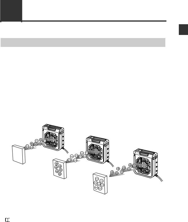
I.C.C. (Ion Current Control) method
This control method calculates the charged level of the target object by sensing the state of ion current that arises due to the potential between the Static Elimination Blower Unit and GND. Optimum static elimination matched to the state of the target object can be performed by rapidly supplying the optimum ions suited to the polarity and charged level of the target object.
Regular state
SJ-F |
010 |
Elimination of (+) ions |
from target object
SJ-F010 |
Elimination of (–) ions |
|
from target object |
|
SJ-F010 |
Target object in non-charged state
Target object (+) charged
Target object (–) charged
Fan speed adjustment function
The blast from the Static Elimination Blower Unit is adjusted. This fulfils a vital role in improving static elimination speed and extends the static elimination area.
"Fan Speed Adjustment Function" (page 3-1)
1
F100W/100/010-SJ Unit Blower Elimination Static the About
1-1
1
F100W/100/010-SJ Unit Blower Elimination Static the About
1-1 Features of the SJ-F100W/100/010
Ion monitor function
●Charge monitor
The integrated ion monitor allows you to learn how much the target object is charged by + or - ions. This monitor also allows you to confirm at a glance how static elimination is being performed.
●Ion level monitor
The ion level currently being generated by the Static Elimination Blower Unit is monitored at all times so that drops in the generated ion level can be diagnosed on the unit. The generated ion level is indicated by LEDs and an alarm can be output when the generated ions fall below a certain level. This allows you to monitor the influence of dirty electrode needles in advance.
"Ion Monitor Functions" (page 3-2)
Alarm output functions
●Alarm output functions
An indicator blinks and an alarm signal is output, for example, when internal circuits are damaged or abnormal discharging occurs. When an alarm signal is output, generation of ions is forcibly stopped.
●Ion level alarm output function
An indicator lights and an alarm signal is output when the amount of generated ions drops due to dirty electrode needles, for example.
●Condition alarm output function
An indicator lights and an alarm signal is output when static elimination performance is influenced by an unstable installation environment (temperature, humidity, surrounding metal objects, etc.)
"Alarm Output Functions" (page 3-3)
Abnormal discharge detection function
Abnormal discharge caused by condensation on the electrode needle tips or adhesion of debris is detected. When abnormal discharge is detected, ion generation is forcibly stopped to prevent trouble at an early stage.
"Abnormal Discharge Detection Function" (page 3-4)
Ion balance adjustment function
The ion balance zero point can be fine-adjusted.  "Ion Balance Adjustment Function" (page 3-4)
Static elimination stop function
Static elimination only can be turned ON/OFF with the device still powered. This is achieved by shorting the 0V terminal with the static elimination stop input terminal on the Controller Unit (I/O terminal section) or by holding down the two ion balance adjustment keys simultaneously for about three seconds.
"Static Elimination Stop Function" (page 3-6)
Low voltage power-saving wiring
Low-voltage wiring eliminates deterioration of cables caused by discharging and eliminates the influence on surrounding devices. This enables you to build a highly reliable system.
1-2

1-2 Checking the Contents of the Package
The package contains the following components and accessories. Before you start using SJ-F100W/100/ 010, make sure that the package contains everything that it is supposed to contain. Mounting fixtures, Replacement Electrode Unit and other accessories are available as options.
"List of Options" (page A-7)
Package Contents
Static Elimination Blower Unit |
Controller Unit |
Instruction Manual |
(SJ-F010) |
(SJ-F100W/100) |
|
SJ-F010
Earth lead
Options
Mounting fixture A (OP-51409)
BALANCE |
ION |
|
SJ-F100W |
|
|
|
|||
+ |
|
|
ALARM |
|
|
|
ION |
|
|
|
|
|
LEVEL |
H |
|
|
|
|
M |
|
|
|
|
L |
0 |
|
|
|
|
|
|
|
COND |
H |
|
|
|
|
M |
|
|
|
|
L |
– |
|
|
DISP |
|
|
|
|
|
|
ION BALANCE |
|
|
|
|
ADJAST |
|
|
FAN SPEED |
|
|
|
|
SLOW |
FAST |
|
|
|
|
|
CONDITION |
ION LEVEL |
|
|
|
24V |
INTERRUPT |
|
||
DC |
|
|
||
|
OV |
ALARM |
|
|
High-speed, High-precision
Compact Static Emilination Blower
SJ-F100W/100/010
Instruction Manual
WARNING labels (Japanese, German, French and Italian)
* Use them as necessary.
Mounting fixture B |
Replacement Electrode |
(OP-51410) |
Unit (OP-51407) |
1
F100W/100/010-SJ Unit Blower Elimination Static the About
*1 |
This fixture is provided with |
*1 |
This fixture is provided with |
||||
|
four M4 screws for mounting |
|
four M4 screws for mounting |
||||
|
the Static Elimination Blower |
|
the Static Elimination Blower |
||||
|
Unit. |
|
Unit. |
||||
*2 |
For details on how to install |
*2 |
For details on how to install |
||||
|
mounting fixture A, see |
|
|
|
mounting fixture B, see |
|
|
|
|
|
|
||||
|
"When using mounting fixture |
|
"When using mounting fixture |
||||
|
A:" (page 2-4). |
|
B:" (page 2-5). |
||||
1-3
1
F100W/100/010-SJ Unit Blower Elimination Static the About
1-3 Names and Functions of Parts
This section describes the names and functions of parts on the SJ-F100W/100/010.
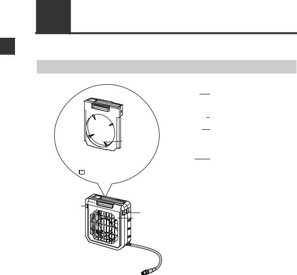
Static Elimination Blower Unit
(1) Electrode Unit |
(1) Electrode Unit |
The electrode needles are fixed on the |
|
|
Electrode Unit. Remove this unit from the |
|
|
Static Elimination Blower during |
|
|
maintenance and inspection. |
(2) |
Electrode needles |
Ion charge is emitted from the tips of these |
|
|
|
needles. |
|
(3) |
Power indicator |
Indicates the operating state of the |
|
|
|
SJ-F100W/100/010. |
|
(2) Electrode |
|
Lit (green): |
Regular operation |
needle |
|
Lit (red): |
Static elimination is stopped. |
|
|
Blinking (red): |
Alarm has occurred. |
For details on how to install and remove |
(4) Lock switch |
Fixes the Electrode Unit to the Static |
|||
the Electrode Unit, see "Performing |
|||||
|
Elimination Blower. |
||||
Maintenance on the Electrode Needles" |
|
||||
|
|
||||
( |
|
page 4-2). |
|
|
|
|
|
|
|||
(3) Power indicator |
SJ- |
|
F010 |
|
(4) Lock switch |
|
Fan guard (metal) |
1-4
1-3 Names and Functions of Parts
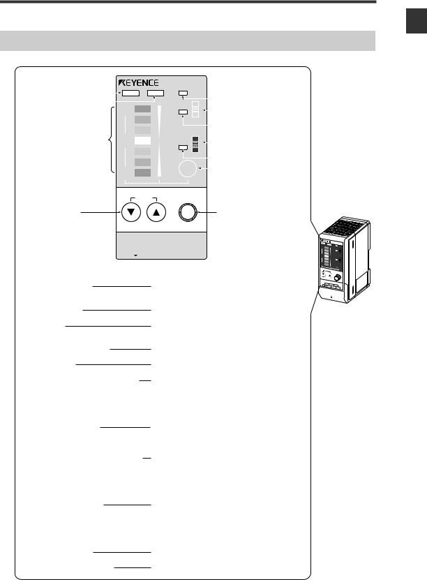
Controller Unit (operation/display section)
|
|
|
|
|
|
|
|
SJ-F100W |
|
|
|
|||
(1) Ion balance indicator |
|
|
|
|
|
|
|
ALARM |
|
|
|
|||
|
|
BALANCE |
|
ION |
|
|
|
(5) |
Alarm indicator |
|||||
(2) Ion level indicator |
|
|
|
|
|
|
|
|
|
|
|
|
||
|
+ |
|
|
ION |
|
H |
|
|
|
|||||
|
|
|
|
LEVEL |
|
M |
|
(6) |
Ion level alarm sensitivity |
|||||
|
|
|
|
|
|
|
||||||||
|
|
|
|
|
|
|
|
|
|
L |
|
|
setup switch |
|
|
|
|
|
|
|
|
|
|
|
|
|
|
|
|
(3) Ion monitor |
0 |
|
|
|
|
|
|
|
|
(7) |
Ion level alarm indicator |
|||
|
|
|
|
|
H |
|
||||||||
|
|
COND |
|
|
(8) |
Condition alarm sensitivity |
||||||||
|
|
|
|
|
M |
|||||||||
|
|
|
|
|
|
|
|
|
|
L |
|
|
setup switch |
|
|
|
|
|
|
|
|
|
|
|
|
|
|
(9) |
Condition alarm indicator |
|
|
|
|
|
|
|
|
|
|
|
|
|
||
|
|
|
– |
|
|
|
DISP |
|
|
(10) Display selector key |
||||
|
|
|
|
|
|
|
|
|||||||
|
|
|
|
|
|
|
|
|
|
|
|
|
||
|
|
|
|
|
|
|
|
|
|
|
|
|
|
|
ION BALANCE |
FAN SPEED |
ADJUST |
|
(4) Ion balance |
(11) Fan speed adjustment knob |
adjustment key |
|
SLOW |
FAST |
|
|
|
CONDITION |
ION LEVEL |
INTERRUPT |
|
|||||
|
|
|
|
|
|
|
|
|
|
|
|
|
|
|
|
|
24V DC |
OV |
ALARM |
|
|||
Enlarged view of front panel display |
|||||||||||
(1) Ion balance indicator |
Lights when the charged level of the target object is |
||||||||||
|
|
|
|
|
|
displayed. |
|||||
BALANCE |
ION |
|
SJ-F100W |
|
|
|
|||
+ |
|
|
ALARM |
|
|
|
ION |
|
|
|
|
|
LEVEL |
H |
|
|
|
|
M |
|
|
|
|
L |
0 |
|
|
|
|
|
|
|
COND |
H |
|
|
|
|
M |
|
|
|
|
L |
– |
|
|
DISP |
|
|
|
|
|
|
ION BALANCE |
|
|
|
|
ADJUST |
|
|
FAN SPEED |
|
|
|
SLOW |
|
|
|
|
|
|
FAST |
24V |
DC |
OV |
|
|
|
ALARM |
|
||
(2) |
Ion level indicator |
Lights when the ion emission level is being displayed. |
|
|
|
||||
|
|
Terminal plate cover |
||
(3) |
Ion monitor |
Indicates the charged level of the target object. Also, |
||
|
|
indicates the ion emission level. |
||
(4) |
Ion balance adjustment key |
Used for adjusting the ion balance. |
||
(5) |
Alarm indicator |
Blinks when an alarm occurs. |
||
(6) |
Ion level alarm sensitivity setup switch |
Changes the threshold at which the ion level alarm is |
||
|
|
output. |
||
|
|
H: High sensitivity |
||
|
|
M: Medium sensitivity |
||
|
|
L: Low sensitivity |
||
(7) |
Ion level alarm indicator |
Blinks when the ion emission level has fallen below |
||
|
|
the set value due to dirt or wear of the electrode |
||
|
|
needles. |
||
(8) |
Condition alarm sensitivity setup switch |
Changes the threshold at which the condition alarm is |
||
|
|
output. |
||
|
|
H: High sensitivity |
||
|
|
M: Medium sensitivity |
||
|
|
L: Low sensitivity |
||
(9) |
Condition alarm indicator |
Blinks when static elimination performance is |
||
|
|
influenced by the instability of the installation |
||
|
|
environment (temperature, humidity, surrounding |
||
|
|
metal objects, etc.), for example, when ions are being |
||
|
|
absorbed by surrounding metal objects. |
||
(10) Display selector key |
Selects the ion monitor display. |
|||
(11) Fan speed adjustment knob |
Adjusts the fan speed. |
|||
1
F100W/100/010-SJ Unit Blower Elimination Static the About
1-5
Loading...