


 Loading...
96M12738
All-Purpose Laser Sensor
LR-TB2000 Series
Instruction Manual
Read this manual before using the product in order to achieve maximum performance. Keep this manual in a safe place after reading it so that it can be used at any time.
The following symbols alert you to important messages. Be sure to read these messages carefully.
|
|
|
It indicates a hazardous situation which, if not avoided, could result in |
|
WARNING |
|
|
|
|
death or serious injury. |
|
|
|
|
|
|
|
|
|
|
NOTICE |
It indicates a situation which, if not avoided, could result in product |
|
|
damage as well as property damage. |
||
|
|
|
|
|
|
|
|
1 Introduction
Safety Information for LR-TB Series
|
|
|
• This product is only intended to detect object(s). Do not use this |
|
|
|
product for the purpose to protect a human body or part of a human |
|
|
|
body. |
|
|
• This product is not intended for use as an explosion-proof product. |
|
|
WARNING |
|
|
|
|
|
Do not use this product in a hazardous location and/or potentially |
|
|
|
|
|
|
|
explosive atmosphere. |
|
|
|
• This product uses DC power. The product may explode or burn if an |
|
|
|
AC voltage is applied. |
|
|
|
|
|
|
|
• Do not wire the cable along with power lines or high-tension lines, |
|
|
|
as the sensor may malfunction or be damaged due to noise. |
|
|
|
• When using a commercially available switching regulator, ground |
|
NOTICE |
the frame ground terminal and ground terminal. |
|
|
|
|
• Do not use this product outdoors or in a location in which its |
|
|
|
light-receiving surface will come in direct contact with stray ambient |
|
|
|
light. |
|
|
|
|
Safety Precautions on Laser Product
This product uses a semiconductor laser as its light source.
•Use of controls or adjustments or performance of procedures other than those specified herein may result in hazardous radiation exposure.
•Follow the instructions mentioned in this manual. Otherwise, injury to the human body (eyes and skin) may result.
•Laser emission from this product is not automatically stopped when it is disassembled. Do not disassemble this product.
•Precautions on Class 2 Laser Product
- Do not stare into the direct or specularly reflected beam.
WARNING |
- Do not direct the beam at people or into areas where people |
|
might be present. |
|
- Be careful of the path of the laser beam. |
|
If there is a possibility that the operator may be exposed to the |
|
specular or diffuse reflections, block the beam by installing a |
|
protective enclosure. |
-Install this product so that the path of the laser beam is not as the same height as that of human eye.
•Precautions on Class 1 Laser Product
-Do not stare into the direct or specularly reflected beam.
|
Item |
|
Description |
||
Model |
|
|
LR-TB2000 |
|
LR-TB2000CL |
|
|
|
|
||
|
|
LR-TB2000C |
|
||
|
|
|
|
|
|
|
|
|
|
|
|
Wavelength |
|
|
660 nm |
|
|
|
|
|
|
|
|
Pulse width |
|
|
4.3 ns |
|
|
|
|
|
|
|
|
FDA(CDRH) |
|
Laser class* |
Class 2 laser product |
|
Class 1 laser product |
Part1040.10 |
|
Output |
1.0 mW |
|
390 μW |
|
|
|
|
|
|
JIS C 6802/ |
|
Laser class |
Class 2 laser product |
|
Class 1 laser product |
IEC 60825-1 |
|
Output |
1.0 mW |
|
390 μW |
|
|
|
|
|
|
*The laser classification for FDA (CDRH) is implemented based on IEC60825-1 in accordance with the requirements of Laser Notice No.50.
Laser warning and explanation labels
-XXXX XX 

 15671234


Laser warning and
explanation label
Laser emission point
zLaser warning and explanation labels
•Attached to the cable
Class 2 (English) |
Class 1 |
•Included with the product
Class 2 (included with the product in each language)
*For a Class 2 laser product, select from the warning and explanation labels included in the package the appropriate warning and explanation label according to the country and region where the Class 2 laser product will be used. Then, affix the warning and explanation label over top of the existing warning and explanation label on the product.
Precautions on Regulations and Standards
CSA Certificate
LR-TB series complies with the following CSA and UL standards and has been certified by CSA (Class 2252 06 / Class 2252 86).
• Applicable standard: CAN/CSA C22.2 No.61010-1 UL61010-1
• Use the following power supply.
CSA/UL certified power supply that provides Class 2 output as defined in the CEC (Canadian Electrical Code) and NEC (National Electrical Code), or CSA/UL certified power supply that has been evaluated as a Limited Power Source as defined in CAN/ CSA-C22.2 No. 60950-1/UL60950-1
•Use this product at the altitude of 2000 m or less.
•Use this product at the level of overvoltage category I.
•Use this product at pollution degree 3.
•Indoor use only.
CE Marking
Keyence Corporation has confirmed that this product complies with the essential requirements of the applicable EC Directive, based on the following specifications.
Be sure to consider the following specifications when using this product in a member state of the European Union.
z EMC Directive (2004/108/EC)
• Applicable standard EMI : EN60947-5-2, Class A EMS : EN60947-5-2
z Low-voltage Directive (2006/95/EC)
•Applicable standard: EN61010-1, EN60825-1
•Use the power supply that has been evaluated as a Limited Power Source as defined in IEC60950-1/EN60950-1.
•Use this product at the altitude of 2000 m or less.
•Use this product at the level of overvoltage category I.
•Use this product at pollution degree 3.
•Indoor use only
Remarks: These specifications do not give any guarantee that the end-product with this product incorporated complies with the essential requirements of the EMC Directive.
The manufacturer of the end-product is solely responsible for the compliance of the end-product itself according to the EMC Directive.
1
Package Contents
•Main unit
•Instruction manual
•Laser warning and explanation labels (LR-TB2000/TB2000C only)
Specifications
|
|
Cable |
LR-TB2000 |
- |
||
Model |
|
Cable with |
LR-TB2000C |
LR-TB2000CL |
||
|
|
connector M12 |
||||
|
|
|
|
|
|
|
Detectable distance*1 |
|
|
60 to 2000 mm |
|||
Spot diameter |
|
|
|
Approx. 4 mm |
||
|
|
|
|
|
|
|
|
|
|
1 ms/10 ms/25 ms/ |
2 ms/20 ms/50 ms/ |
||
Response time |
|
100 ms/1000 ms |
200 ms/2000 ms |
|||
|
|
|
selectable |
selectable |
||
|
|
|
|
|
|
|
|
|
Type |
|
|
Red laser (660 nm) |
|
|
|
|
|
|
|
|
Light source |
|
|
Class 2 laser product |
Class 1 laser product |
||
|
Laser class |
IEC60825-1,FDA(CDRH) |
IEC60825-1,FDA(CDRH) |
|||
|
|
|||||
|
|
|
Part1040.10*2 |
Part1040.10*2 |
||
Mutual interference prevention |
4 units (when using the interference prevention function) |
|||||
function |
|
|||||
|
|
|
|
|
||
|
|
|
|
|
||
Timer |
|
|
OFF/OFF delay/ON delay/One-shot |
|||
|
|
|
|
|||
Power voltage |
|
20 to 30 VDC, including 10% ripple (P-P), Class 2 or LPS |
||||
|
|
|
|
|||
Current consumption |
|
|
45 mA or less (without load)*3 |
|||
|
|
|
NPN open collector/PNP open collector selectable |
|||
|
|
Control output |
|
|
30 VDC or less, 50 mA or less, |
|
|
|
|
residual voltage: 2 V or less, N.O./N.C. selectable |
|||
|
|
|
|
|
|
|
|
|
|
|
|
Transmission OFF / Tuning / |
|
I/O*4*5 |
|
|
Reference surface update selectable |
|||
|
|
|
Short-circuit current: 1 mA or less for both NPN and PNP |
|||
|
|
External input |
For the applied voltage, see the wiring diagrams |
|||
|
|
|
( |
|
page 2 in the instruction manual). |
|
|
|
|
|
|||
|
|
|
For the input times, see the time charts |
|||
|
|
|
( |
|
page 3 in the instruction manual). |
|
|
|
|
|
|||
|
|
|
|
|
|
|
|
|
|
Protection against reverse power connection, |
|||
Protection circuit |
power supply surges, output overcurrent, output surge, |
|||||
|
|
|
|
|
and reverse output connection |
|
|
|
|
|
|
|
|
|
|
Enclosure rating |
|
|
IP65/IP67 (IEC60529) |
|
|
|
|
|
|
||
|
|
Ambient light |
Incandescent lamp/Sunlight: 100000 lux or less |
|||
|
|
|
|
|
|
|
|
|
Ambient |
|
|
-20 to +55°C (no freezing) |
|
Environmental |
|
temperature |
|
|
||
|
|
|
|
|
||
resistance |
|
Ambient humidity |
|
|
35 to 85%RH (no condensation) |
|
|
|
|
|
|
||
|
|
Shock resistance |
1000m/s2 in X, Y, Z axis directions respectively 6 times |
|||
|
|
Vibration resistance |
10 to 55 Hz Double amplitude 1.5 mm in the X, Y, Z axis |
|||
|
|
|
|
directions respectively, 2 hours |
||
|
|
|
|
|
||
|
|
|
|
|
|
|
|
|
|
Case: Zinc die cast (Nickel chrome plating), Indicator cover |
|||
|
|
|
and buttons: PES, Lens cover and display: PMMA |
|||
Material |
|
(scratch-resistant coating specifications), |
||||
|
|
|
Cable bushing: PBT, Cable: PVC, |
|||
|
|
|
|
|
||
|
|
|
M12 connector (only for the cable with connector M12 type): |
|||
|
|
|
|
|
TPE, PBT, Nickel-plated brass |
|
|
|
|
|
|
||
Weight |
|
Cable type: Approx. 125 g (Including cable) |
||||
|
Cable with connector M12 type: Approx. 85 g |
|||||
|
|
|
||||
|
|
|
|
|
|
|
*1 The range for displayable distance is from 50 to 2200.
*2 The laser classification for FDA (CDRH) is implemented based on IEC60825-1 in accordance with the requirements of Laser Notice No.50.
*3 145mA or less (with load)
*4 You can select the I/O from the following combinations. Control output × 2, control output + external input
(For details on the setting method, see  page 3 of the instruction manual.) *5 IO-Link specification v.1.1/COM2 (38.4 kbps) is supported.
You can download a setup file from the KEYENCE website (http://www.keyence.com). If you are using the product in an environment in which you cannot download files over the Internet, contact your nearest KEYENCE office.
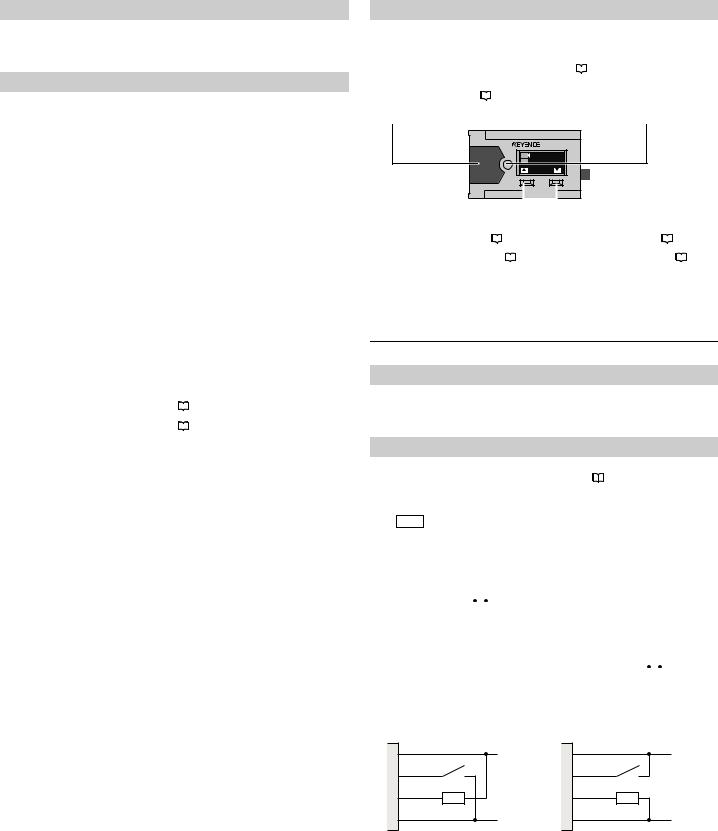
Part Functions
Indicator |
|
|
|
|
[SET] Button |
|||
Output 1 |
ON : Orange* |
|
|
|
|
The operation of this button varies |
||
Output 1 |
OFF : Green* |
|
|
|
|
depending on the detection mode |
||
Error |
: Flashing red |
|
|
|
|
( |
|
page 4). |
|
|
|
|
|
||||
* The indicator flashes when two conditions below |
|
Example: 2-point calibration |
||||||
are met; |
|
|
|
|
1. |
|
Press this button with no workpiece |
|
• Stability output turns ON ( |
|
|
page 9). |
|
|
|
present. |
|
|
|
|
|
|||||
• Output 1 turns OFF when |
output logic is N.O. or |
|
2. |
|
Press this button with a workpiece |
|||
turns ON when output logic is N.C. |
|
|
|
present. |
||||
|
|
|
|
|
|
|
|
|
|
XX-XXXX |
1 |
1567 |
2 |
|
|
1234 |
DISP |
MODE |
|
|
|
|
|
|
|
|
|
|
|
|
|
|
|
|
|
|
|
|
|
|
|
|
|
|
|
|
|
|
|
|
|
|
|
|
|
|
|
|
|
|
|
|
|
|
|
|
|
|
|
[DISP/S] Button |
|
|
|
|
[MODE/T] Button |
|
|
|
|
|
||||||
Pressed for 1 second or less: |
|
|
|
|
Pressed for 1 second or less: |
|
|
|
|
|
||||||
Changes the setting value ( |
|
|
page 6) |
|
|
Changes the setting value ( |
|
|
|
page 6) |
||||||
|
|
|||||||||||||||
Held for 3 seconds or more: |
|
|
|
|
|
|
Held for 3 seconds or more: |
|
|
|
|
|
|
|
|
|
Switches to the display screen ( |
|
page |
|
|
Switches to the setting screen ( |
|
|
|
page |
|||||||
|
|
|||||||||||||||
7) |
|
|
|
|
|
|
8) |
|
|
|
|
|
|
|
|
|
|
|
|
|
|
|
|
|
|
|
|
|
|
|
|
|
|
For a more detailed explanation, see  "Switching between Display Screens" (page 7).
2 Installation and Wiring
Installation
•Tightening torque for the mounting holes: 0.63 N·m (M3 screw)
•If the detecting object has a mirrored surface, install the sensor in a position where specular reflection will not penetrate the optical receiver.
Wiring
With the LR-TB Series, you can select the functions of the I/O wires (black and white) from the combinations shown below during the initial settings. "3 Initial Settings" (page 3) Independently isolate any I/O wires that you will not use.
Load (input device)
Out1+Out2
z NPN |
|
z PNP |
|
||||||||||||
|
|
1, brown |
20 ... 30 V |
|
|
1, brown |
20 ... 30 V |
||||||||
|
|
|
|
||||||||||||
|
|
|
|
|
|
|
|
|
|
|
|
|
|
||
|
|
4, black |
|
|
|
|
|
|
|
4, black |
|
|
|
||
|
|
|
|
|
|
|
|
|
|
|
|
|
|
|
|
|
|
2, white |
|
|
|
|
|
|
|
2, white |
|
|
|
|
|
|
|
|
|
|
|
|
|
|
|
|
|
||||
|
|
|
|
|
|
|
|
|
|
|
|
|
|
|
|
|
|
|
|
|
|
|
|
|
|
|
|
|
|
|
|
|
|
3, blue |
0 V |
|
|
3, blue |
|
|
0 V |
||||||
|
|
|
|
|
|
|
|
|
|
|
|
|
|
||
|
|
|
|
|
|
|
|
|
|
|
|
|
|
|
|
|
Input+Out1 |
|
z |
NPN |
|
|
1, brown |
20 ... 30 V |
|
|
|
|
4, black |
|
|
2, white |
|
|
3, blue |
0 V |
|
|
z |
PNP |
|
|
1, brown |
20 ... 30 V |
|
|
|
|
4, black |
|
|
2, white |
|
|
3, blue |
0 V |
|
|
2
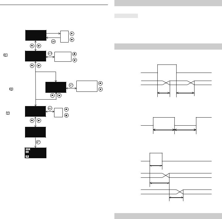
3 Initial Settings
When you turn on the LR-TB Series for the first time after you purchase it or when you have initialized the LR-TB Series, the following initial settings must be configured.
Display Units
 and
and Press for 3 seconds or more
mm
Start Config.
inch feet
3-1. I/O Selection |
Select I/O |
|
|
|
||
( |
page 3) |
Out1+Out2 |
Out1+Out2 |
|
||
|
|
|
Input+Out1 |
|
||
|
|
|
|
|
|
|
|
|
Out1+Out2 |
Input+Out1 |
|
||
|
3-2. External Input |
|
|
Select Input |
Laser Off |
|
|
Selection |
|
|
Laser Off |
Tuning |
|
|
( |
page 3) |
|
|
DATUM Preset |
|
|
|
|
|
|||
3-3. NPN/PNP |
Select Output |
|
|
|||
Selection |
|
|
||||
NPN |
|
NPN |
|
|||
( |
|
page 3) |
|
|
||
|
|
|
PNP |
|
||
|
|
|
|
|
|
|
|
|
|
End Config. |
|
|
|
1
2 1234 RUN
500 
•After you have finished configuring the initial settings, you will not be able to reconfigure the unit, I/O, or NPN/PNP selection. To change any of these settings, you will have to initialize the product.  "Initialization" (page 7).
3-1. I/O Selection
Select from the following table the functions assigned to the I/O wires (black and white).
Options |
Black Wire |
White Wire |
Out1 + Out2 |
Output 1 |
Output 2 |
|
|
|
Input + Out1 |
External input |
Output 1 |
|
|
|
The functions assigned to output 1, output 2, and external input can be changed after you finish configuring the initial settings.  "6 Detailed Settings" (page 8).
3-2. External Input Selection
Transmission OFF [Laser Off]
The laser beam transmission is stopped.
ON
Input
OFF
Transmission |
OFF |
Transmission |
|
< 5 ms |
< 50 ms |
External Calibration [Tuning]
When selected, this external input performs the same function as pressing the [SET] button.
ON
Input
OFF
> 60 ms |
> 60 ms |
Reference surface update [DATUM Preset]
When the detection mode ( "4 Detection Mode" [page 4]) is set to "DATUM mode," this external input updates the reference surface.
ON
Input
OFF
> 5 ms
Updated reference surface
< 60 ms
Updated output
Response
time
3-3. NPN/PNP Selection
You can select between NPN outputs or PNP outputs. For details, see  "Wiring" (page 2).
3

4 Detection Mode
The LR-TB Series has four output modes and three detection modes.
Output Mode ( |
page 9) |
|
|
Detection Mode |
|
Standard (default value) [Standard] |
4-1. DATUM mode (FGS) |
||||
|
|
|
|||
4-2. Distance mode (BGS) |
|||||
|
|
||||
|
|
|
|
||
Window [Window] |
4-3. Window mode |
||||
|
|
|
|
|
|
Stability [Stability] |
( |
|
page 9) |
||
|
|||||
|
|
|
|
|
|
Error [Error] |
( |
|
page 9) |
||
|
|||||
|
|
|
|
|
|
When the output modes for Out1 & Out2 are either [Standard] or [Window], the detection modes can only be set in the below combinations.
[Out1] / [Out2] = [DATUM]/ [DATUM], [Distance]/ [Distance], [Distance]/ [Window], [Window]/ [Distance], [Window]/ [Window]
4-1. DATUM Mode (FGS)
Operation
•In this mode, the change in position from a reference surface (which has a value of 0) is displayed.
•This mode is useful in detecting the passage of workpieces in front of a stationary background.
Reference surface
-A 0 A
|
XX-XXXX |
1 |
1567 |
2 |
|
|
1234 |
DISP |
MODE |
A: Setting value
ON
N.O.
OFF
ON
N.C.
OFF
Hys. |
Hys. Hys: Hysteresis ( |
page 10) |
Setting
•Set the output mode to [Standard], which is the default mode.  "6 Detailed Settings" (page 8)
•For details on setting output 2, see  " 4-5. Switching Out1/Out2" (page 6).
•In DATUM mode, a "±" is displayed in front of the setting value.
Reference surface
1
|
XX-XXXX |
1 |
1567 |
2 |
|
|
1234 |
DISP |
MODE |
Press the set button for 1 second or less.
2
|
XX-XXXX |
1 |
1567 |
2 |
|
|
1234 |
DISP |
MODE |
Press and hold the set button for 3 seconds or more.
Completion
-A A
N.O. ON
OFF
N.C. ON
OFF
4-2. Distance Mode (BGS)
Operation
• In this mode, the distance from the sensor is displayed.
2000 |
A |
0 |
|
|
|
|
|
|
XX-XXXX |
1 |
1567 |
2 |
|
|
1234 |
DISP |
MODE |
A: Setting value
ON
N.O.
OFF
ON
N.C.
OFF
Hys. Hys: Hysteresis ( page 10)
Setting
•Set the detection mode to [Standard], which is the default value.  "6 Detailed Settings" (page 8)
•For details on setting output 2, see " 4-5. Switching Out1/Out2" (page 6)
z 2-point calibration
1
|
XX-XXXX |
1 |
1567 |
2 |
|
|
1234 |
DISP |
MODE |
Press the set button for 1 second or less.
2
|
XX-XXXX |
1 |
1567 |
2 |
|
|
1234 |
DISP |
MODE |
Press the set button for 1 second or less.
Completion
Setting value
|
XX-XXXX |
1 |
1567 |
2 |
|
|
1234 |
DISP |
MODE |
N.O. ON
OFF
N.C. ON
OFF
4
Loading...