


 Loading...
96M1573
High-speed, High-accuracy
CCD Laser Displacement Sensor
LK-G Series
User’s Manual
Read this manual before using the system in order
to achieve maximum performance.
Keep this manual in a safe place for future
reference.

Introduction
This Instruction Manual describes the basic operations and hardware functions of the LK-G Series. Read this manual carefully to ensure the optimum performance and full function of the LK-G Series before use.
Keep this manual in a safe place for future reference.
Be sure that the person who will finally operate this product receives this manual.
■ Symbols
These symbols alert you to matters concerning the prevention of human injury and product damage.
 DANGER
Failure to follow the instructions may lead to death or serious injury.
 WARNING
Failure to follow the instructions may lead to injury.
 CAUTION
Failure to follow the instructions may lead to product damage or failure of the product.
Note
Provides additional information on proper operations that can be easily mistaken.
Reference
Provides advanced and useful information for operation.

Safety Precautions
General Cautions
•At startup and during operation, be sure to monitor the functions and performance of the LK-G Series.
•We recommend that you take substantial safety measures to avoid any damage in the event of a problem occurring.
•Do not attempt to open or modify the LK-G Series or use it in any way other than as described in the specifications. If the LK-G Series is modified or used other than as described, the warranty will be voided.
•When the LK-G Series is used in combination with other devices, functions and performance may be degraded, depending on the operating conditions and surrounding environment.
•Do not use the LK-G Series for the purpose of protecting the human body.
•Do not allow the temperature to change sharply around the LK-G Series, including the accessories. Otherwise, condensation may lead to malfunction.
 WARNING
Follow the safety precautions below to ensure safe operation
•Apply the correct power voltage. Failure to do so may cause fire, electric shock, or malfunction.
•Do not attempt to disassemble or modify the unit. Doing so may cause fire or electric shock.
Handling abnormalities
Turn off the power immediately in the following cases. Using the unit in an abnormal condition could cause fire, electric shock, or accident.
Contact the nearest KEYENCE office for repair.
•If liquid including water, chemicals or debris enters the unit.
•If the unit is dropped or the case is damaged.
•If abnormal smoke or odor is present.
LK-G-M-NO0-E |
1 |

 CAUTION
Follow the safety precautions below to ensure safe operation
•Be sure to turn the power off when you plug/unplug the cable that leads to the unit and its accessories. Not following this caution may result in damage.
•Do not turn off the power while setting items. The data being set or all the data may be lost.
•Do not block the vent holes on the unit. Increase of internal temperature may cause failure.
Installation environment
To use the LK-G Series correctly and safely, avoid installing it in the following locations; doing so may lead to breakdown of the unit.
•Location that is humid, dusty or poorly ventilated
•Location with a high temperature such as a place exposed to direct sunlight
•Location where there are flammable or corrosive gases
•Location where the unit may be directly subjected to vibration or impact
•Location where water, oil or chemicals may splash onto the unit
•Location where static electricity is easily generated
Corrective action for noise
Do not install the LK-G Series near a power source or high-voltage cable, otherwise noise may cause the LK-G Series to malfunction. Take corrective action for noise by using noise filters, laying cables separately, and/or installing insulation on the controller and the measuring unit. Use the single core shielded cable for the analog output cable.
Influence of ambient temperature
A change in the ambient temperature may cause the measurement to fluctuate. Be sure to keep it stabilized. When the ambient temperature changes by 10 °C, it takes 60 minutes for the distribution of internal temperature to equalize.
Operating ambient light intensity level
Do not use the LK-G Series near a lighting system that repeatedly and rapidly turns on and off. If it is unavoidable to use the unit in such a place, install a light shielding board or the like so that the light will not affect the measurement.
Warming up
Before using the LK-G Series, wait approximately 30 minutes after the power is turned on. Otherwise, the measured value may gradually fluctuate because the circuit is not immediately stable after the power is turned on.
2 |
LK-G-M-NO0-E |

Influence of dust or dirt
The measurement may fluctuate due to dirt, dust or fluid such as water or oil in the following cases:
•Adhesion on the protection glass: Blow the dirt off with clean air. If dirt persists, wipe the glass surface gently using a soft cloth moistened with alcohol.
•Adhesion on the surface of the measuring target: Blow the dirt off with clean air or wipe it off.
•Intrusion of floating or sprinkled dust or dirt into the light-axis range: In this case, take corrective action with a protective cover or air purge.
Notes
Influence of vibration
When the measuring target is vibrating, the measured value may fluctuate. In this case, increase the average number of times of measurement to achieve a more accurate value.
Measuring target
The measured value may fluctuate if the shapes or surfaces of the measuring targets vary. In this case, use a known target and perform appropriate correction using the calibration function.
Handling
Do not wipe with a wet cloth, benzene, or thinner. Doing so may change the color or shape of the unit. If the unit has much dirt on it, wipe it off with a cloth moistened with a mild detergent, then wipe with a soft dry cloth.
Effect of atmospheric motions
Slow atmospheric motions may affect the measurement and result in fluctuation of the measured value. In such a case, take the following countermeasures.
•Enclose the measurement portion with an appropriate enclosure.
•Agitate the air between the measurement portion and the workpiece more strongly with a fan.
Precautions on CE Marking
The LK-G Series conforms to the EMC Directive subject to the conditions that the following requirements are satisfied. In order to use this equipment in the EU countries, be sure that the following requirements have already been satisfied beforehand.
The applicable standards are explained below.
LK-G-M-NO0-E |
3 |
EMI: EN61326, class A EMS: EN61326
Length of the power cord that is connected to the Controller, and length of all input/output cords must be limited to shorter than 30 m.
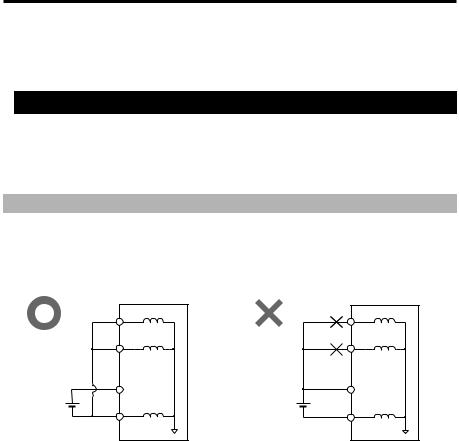
 Precautions for Wiring
Part of the circuits between the inputs and output are internal common. Make sure that a potential difference does not occur between internal common terminals due to a potential difference between wires or external devices. Otherwise, it may cause malfunctions in the unit or external devices.
Examples of Wiring
LK-G3001V/LK-G3001(NPN type)
24 VDC (-), COM OUT (output COM), and COM IN (input COM) are all common via a choke coil. Also, COM OUT and COM IN of the expansion connector are common via a choke coil.
LK-G3001(V) |
LK-G3001(V) |
COM OUT |
COM OUT |
COM IN |
COM IN |
DC24V(+) |
DC24V(+) |
DC24V |
DC24V |
DC24V(-) |
DC24V(-) |
|
The power supply (24 VDC) shorts via the |
|
COM terminals, causing malfunctions. |
4 |
LK-G-M-NO0-E |
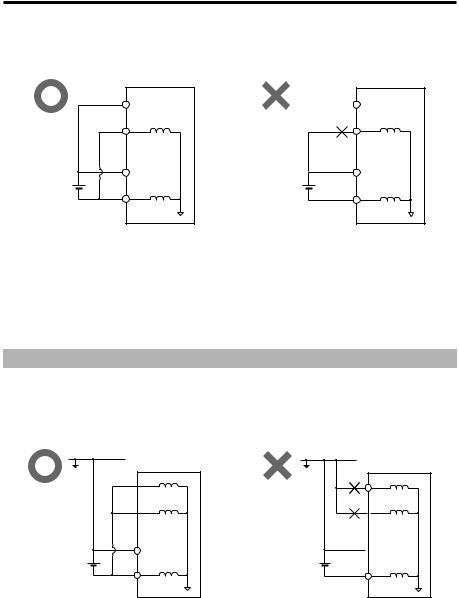
LK-G3001PV/LK-G3001P (PNP type)
24 VDC (-) and COM IN are common via a choke coil. Also, COM IN of the expansion connector is common via a choke coil.
LK-G3001P(V) |
LK-G3001P(V) |
COM OUT |
COM OUT |
COM IN |
COM IN |
DC24V(+) |
DC24V(+) |
DC24V |
DC24V |
DC24V(-) |
DC24V(-) |
|
The power supply (24 VDC) shorts via the |
|
COM terminals, causing malfunctions. |
Common for all types
24 VDC (-), SG (GND) of USB, and SG (GND) of RS-232C are all common via a choke coil. Make sure that a voltage potential difference does not occur with external devices such as computers or PLC. If a voltage potential difference occurs, use the unit with insulation on the LK-G power supply and the I/O terminals other than RS-232C and USB.
Precautions for a Positive Grounding Environment
When using a positive grounding environment, watch out for shorts through the COM terminal.
LK-G3001V/LK-G3001 (NPN type)
GND |
GND |
LK-G3001(V)
 COM OUT
 COM IN
|
DC24V(+) |
DC24V |
DC24V |
LK-G3001(V)
COM OUT
 COM IN
 DC24V(+)
DC24V(-) |
DC24V(-) |
The power supply (24 VDC) shorts via the
COM terminals, causing malfunctions.
LK-G-M-NO0-E |
5 |

LK-G3001PV/LK-G3001P (PNP type)
GND |
GND |
LK-G3001P(V) |
LK-G3001P(V) |
COM OUT |
COM OUT |
COM IN |
COM IN |
DC24V(+) |
DC24V(+) |
DC24V |
DC24V |
DC24V(-) |
DC24V(-) |
|
|
|
The power supply (24 VDC) shorts via the |
|
COM terminals, causing malfunctions. |
Precautions when connecting to computers or other external devices
When working in a positive grounding environment, when the LK-G is connected to a computer through USB in order to use LK-Navigator or when establishing RS-232C communication with a computer, take precautions to avoid shorts in between the SG (GND) terminals for the computer and the LK-G.
24 VDC (-), SG (GND) of USB, and SG (GND) of RS-232C are all common via a choke coil. Make sure that a voltage potential difference does not occur with external devices such as computers or PLC. If a voltage potential difference occurs, use with insulation on the LK-G power supply and the I/O terminals other than RS-232C and USB.
GND
Computer
GND |
RS-232C/ |
RS-232C/ |
|
termin |
USB GND |
||
USB cable |
|||
al |
|
||
|
|
||
|
|
DC24V |
LK-G3001P(V)
RS-232/
USB GND
 DC24V(+)
DC24V(-)
The power supply (24 VDC) shorts via the SG (GND) terminals for LK-G and the computer, causing malfunctions.
Insulate the computer ( in the figure) and LK-G ( in the figure).
* The internal wiring in the computer, PLC, or other device differs depending on the device. For details, refer to the instruction manual for each device.
6 |
LK-G-M-NO0-E |

Safety Precautions on Laser Products
The models of the LK-G Series are classified in terms of laser class as follows:
Model |
|
LK-G35/LK-G30 |
LK-G37/LK-G32 |
LK-G15/LK-G10 |
|
|
|
LK-G85/LK-G80 |
LK-G87/LK-G82 |
|
|
|
|
LK-G155/LK-G150 |
LK-G157/LK-G152 |
|
|
|
|
LK-G405/LK-G400 |
LK-G407/LK-G402 |
|
|
|
|
LK-G505/LK-G500 |
LK-G507/LK-G502 |
|
|
|
|
|
|
|
|
Wavelength |
|
650 nm |
|
|
|
|
|
|
|
|
|
FDA (CDRH) |
Maximum output |
4.8 mW |
0.95 mW |
0.3 mW |
|
Part 1040.10 |
|
|
|
|
|
Class |
Class3a |
Class2 |
Class2 |
||
|
|
|
|
|
|
IEC60825-1: |
Maximum output |
4.8 mW |
0.95 mW |
0.3 mW |
|
1993 + A1: |
|
|
|
|
|
Class |
Class 3R |
Class 2 |
Class 1* |
||
1997 + A2: 2001 |
|||||
|
|
|
|||
|
|
|
|
||
|
|
|
|
|
|
JIS C6802: 1997 |
Maximum output |
4.8 mW |
0.95 mW |
0.3 mW |
|
|
|
|
|
||
Class |
Class 3A |
Class 2 |
Class 1 |
||
|
|||||
|
|
|
|
|
*LK-G15/LK-G10 is a class 1 laser product according to IEC60825-1.
 WARNING
Use of controls or adjustments or performance of procedures other than those specified herein may result in hazardous radiation exposure.
Cautions on class 3a/3R/3A laser products
Observe the following instructions. Otherwise, injury to the human body (eyes and skin) may result.
•Do not direct the laser beam at other persons.
•Never look at the laser beam through optical instruments such as a microscope, magnifier or telescope.
•Make the laser path as short as possible and be sure to terminate the laser path with a diffusion reflector or diffusion absorber so that the laser beam does not diffuse. (It is recommended to install the protection enclosure.)
•Install the laser product so that the laser beam be located well above or below eye level.
•Install the laser product carefully so that the laser beam is not unitentionally directed at mirrorlike surfaces.
•It is recommended to wear protective eye goggles.
•Do not disassemble the LK-G Series.
•Do not look directly at the laser beam.
LK-G-M-NO0-E |
7 |

Cautions on Class 2/ 2 laser products
Observe the following instructions. Otherwise, injury to the human body (eyes and skin) may result.
•Do not direct the laser beam at other persons.
•Do not disassemble the LK-G Series.
•Do not stare at the laser beam.
Cautions on Class 1 laser products
•Do not look directly at the laser beam for an extended period of time.
•Do not disassemble the LK-G Series.
8 |
LK-G-M-NO0-E |
The LK-G Series is equipped with the following safety features based on IEC60825-1 and CDRH Part 1040.10 (Safety of laser products).
■ Laser radiation emission warning indicator
Lights or flashes while the LK-G Series is in operation.
Laser emission |
Laser emission |
Laser emission |
warning indicator |
warning indicator |
warning indicator |
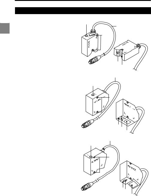
■ Laser remote interlock connector
The laser beam stops radiation emission upon opening the circuit between the REMOTE terminal and the COM IN terminal.
 Refer to "12-pin I/O terminal block" (page 4-2) for connecting terminals.
■ Beam stop or attenuator
The laser beam stops radiation emission by the following operations :
•NPN type: Short-circuiting between the LASER OFF terminal and COM IN terminal.
•PNP type: Apply the voltage between the LASER OFF terminal and COM IN terminal.
Refer to "Expansion Connector" (page 4-5) for connecting terminals.
NPN type
LASER
OFF A
LASER
OFF B
COM IN
REMOTE
COM IN
PNP type
LASER
OFF A
LASER
OFF B
COM IN
*The laser remote interlock connector is delivered with the wire for short-circuiting installed.
Short-circuiting wire
LK-G-M-NO0-E |
9 |
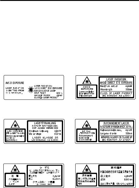
■ Warning labels
The contents of warning indications and locations for attaching warning labels are described below.
The FDA (CDRH) warning labels are attached to the unit when shipped from the factory. Labels other than the FDA (CDRH) label are supplied with the unit. Attach the other label(s) to the locations as shown in the figure on page 9 according to the destinations of the product.
Warning label are not supplied with LK-G15/LK-G10, because these models are IEC class 1 and JIS class 1 products.
■Label contents
●LK-G35/LK-G30/LK-G85/LK-G80/LK-G155/LK-G150/LK-G405/LK-G400/LK- G505/LK-G500
FDA (CDRH) |
|
|
|
|
|
|
|
|
|
|
|
IEC (English) |
||||||||||||||
|
|
|
|
|
|
|
|
|
|
|
|
|
|
|
|
|
|
|
|
|
|
|
|
|
|
|
|
|
|
|
|
|
|
|
|
|
|
|
|
|
|
|
|
|
|
|
|
|
|
|
|
|
|
|
|
|
|
|
|
|
|
|
|
|
|
|
|
|
|
|
|
|
|
|
|
|
|
|
|
|
|
|
|
|
|
|
|
|
|
|
|
|
|
|
|
|
|
|
|
|
|
|
|
|
|
|
|
|
|
|
|
|
|
|
|
|
|
|
|
|
|
|
|
|
|
|
|
|
|
|
|
|
|
|
|
|
|
|
|
|
|
|
|
|
|
|
|
|
|
|
|
|
|
|
|
|
|
|
|
|
|
|
|
|
|
|
|
|
|
|
|
|
|
|
|
|
|
|
|
|
|
|
|
|
|
|
|
|
|
|
|
|
|
|
|
|
|
|
|
|
|
|
|
|
|
|
|
|
|
|
|
|
|
|
|
|
|
|
|
|
|
|
|
|
|
|
|
|
|
|
|
|
|
|
|
|
|
|
|
|
|
|
|
|
|
|
|
|
|
|
|
|
|
|
|
|
|
|
|
|
|
|
|
|
|
|
|
|
|
|
|
|
|
|
|
|
|
|
|
|
|
|
|
|
|
|
|
|
|
|
|
|
|
|
|
|
|
|
|
|
|
|
|
|
|
|
|
|
|
|
|
|
|
|
|
|
|
|
|
|
|
|
|
IEC (German) |
|
|
|
|
|
|
|
|
|
IEC (French) |
||||||||
|
|
|
|
|
|
|
|
|
|
|
|
|
|
|
|
|
|
|
|
|
|
|
|
|
|
|
|
|
|
|
|
|
|
|
|
|
|
|
|
|
|
|
|
|
|
|
|
|
|
|
|
|
|
|
|
|
|
|
|
|
|
|
|
|
|
|
|
|
|
|
|
|
|
|
|
|
|
|
|
|
|
|
|
|
|
|
|
|
|
|
|
|
|
|
|
|
|
|
|
|
|
|
|
|
|
|
|
|
|
|
|
|
|
|
|
|
|
|
|
|
|
|
|
|
|
|
|
|
|
|
|
|
JIS (Japanese) |
|
|
|
|
|
|
|
|
|
|
|
GB (Simplified Chinese) |
|
|||||||
|
|
|
|
|
|
|
|
|
|
|
|
|
|
|
|
|
|
|
|
|
|
|
|
|
|
|
|
|
|
|
|
|
|
|
|
|
|
|
|
|
|
|
|
|
|
|
|
|
|
|
|
|
|
|
|
|
|
|
|
|
|
|
|
|
|
|
|
|
|
|
|
|
|
|
|
|
|
|
|
|
|
|
|
|
|
|
|
|
|
|
|
|
|
|
|
|
|
|
|
|
|
|
|
|
|
|
|
|
|
|
|
|
|
|
|
|
|
|
|
|
|
|
|
|
|
|
|
|
|
|
|
|
|
|
|
|
|
|
|
|
|
|
|
|
|
|
|
|
|
|
|
|
|
|
|
|
|
|
|
|
|
|
|
|
|
|
|
|
|
|
|
|
|
|
|
|
|
|
|
|
|
|
|
|
|
|
|
|
10 |
LK-G-M-NO0-E |

●LK-G37/LK-G32/LK-G87/LK-G82/LK-G157/LK-G152/LK-G407/LK-G402/LK- G507/LK-G502
FDA (CDRH) |
|
|
|
|
|
|
IEC (English) |
||||
|
|
|
|
|
|
|
|
|
|
|
|
|
|
|
|
|
|
|
|
|
|
|
|
|
|
|
|
|
|
|
|
|
|
|
|
|
|
|
|
|
|
|
|
|
|
|
|
|
|
|
|
|
|
|
|
|
|
|
|
|
|
|
|
|
|
|
|
|
|
|
|
|
|
|
|
|
|
|
|
|
|
|
|
|
|
|
|
|
|
|
|
|
|
|
|
|
|
|
|
|
|
|
|
|
|
|
|
|
|
|
|
|
|
|
|
|
|
|
|
IEC (German) |
|
|
|
|
|
|
IEC (French) |
|
|
|
|
|
|
|
|
|
|
|
|
|
|
|
|
|
|
|
|
|
|
|
|
|
|
|
|
|
|
|
|
|
|
|
|
|
|
|
|
|
|
|
|
|
|
|
|
JIS (Japanese) |
|
|
|
|
|
|
|
|
|
GB (Simplified Chinese) |
|||
|
|
|
|
|
|
|
|
|
|
|
|
|
|
|
|
|
|
|
|
|
|
|
|
|
|
|
|
|
|
|
|
|
|
|
|
|
|
|
|
|
|
|
|
|
|
|
|
|
|
|
|
|
|
|
|
|
|
|
|
|
|
|
|
|
|
|
|
|
|
|
|
|
|
|
|
|
|
|
|
|
|
|
|
● LK-G15/LK-G10
FDA (CDRH)
|
|
|
|
|
|
|
|
|
|
|
|
|
|
|
|
|
|
|
|
|
|
|
|
|
|
|
|
|
|
|
|
|
|
|
|
|
|
|
|
|
|
|
|
|
|
|
|
|
|
|
|
|
|
|
|
|
|
|
|
|
|
|
|
|
|
|
|
|
|
|
|
|
|
|
|
|
|
|
|
|
|
|
|
|
|
|
|
|
|
|
|
|
|
|
|
|
|
|
|
|
|
|
|
|
|
|
|
|
|
|
|
|
|
|
|
|
|
|
|
|
|
|
|
|
|
|
|
|
|
|
|
|
|
|
|
|
|
|
|
|
|
|
|
|
|
|
|
|
|
|
|
|
|
|
|
|
|
|
|
|
|
|
|
|
|
|
|
LK-G-M-NO0-E |
11 |
||||||||||||||||||||||
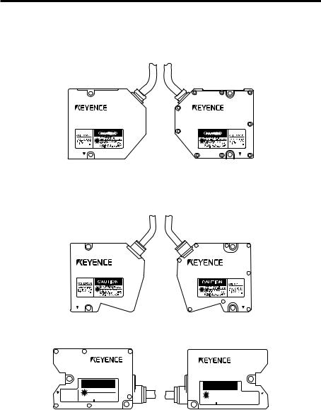
■Label attachment locations
●LK-G35/LK-G30/LK-G37/LK-G32 LK-G85/LK-G80/LK-G87/LK-G82
●LK-G155/LK-G150/LK-G157/LK-G152 LK-G405/LK-G400/LK-G407/LK-G402 LK-G505/LK-G500/LK-G507/LK-G502
● LK-G15/LK-G10
CAUTION
|
LASER RADIATION- |
|
|
AVOID EXPOSURE |
DO NOT STARE INTO BEAM |
||
LASER RADIATION |
SEMICONDUCTOR LASER |
|
|
WAVELENGTH |
650nm |
||
IS EMITTED FROM |
|||
THIS APERTURE. |
MAXIMUM OUTPUT |
0.3mW |
|
|
CLASS LASER PRODUCT |
|
|
12
CAUTION
LASER RADIATION- |
|
|
|
DO NOT STARE INTO BEAM |
AVOID EXPOSURE |
||
SEMICONDUCTOR LASER |
|
|
|
WAVELENGTH |
650nm |
LASER RADIATION |
|
MAXIMUM OUTPUT |
0.3mW |
IS EMITTED FROM |
|
THIS APERTURE. |
|||
CLASS LASER PRODUCT |
|
|
|
LK-G-M-NO0-E

Organization of this Manual
Chapter |
|
Before Use |
|
1 |
|
|
|
Chapter |
|
Operations and Functions |
|
2 |
|
during Measurement |
|
Chapter |
|
Function Settings |
|
3 |
|
|
|
Chapter |
|
Input/Output |
|
|
|
||
4 |
|
Terminals |
|
Chapter |
|
RS-232C |
|
|
|
||
5 |
|
|
|
Chapter |
|
Specifications |
|
6 |
|
|
|
Appendices |
|
Appendices |
|
|
|
|
|
|
|
|
|
Describes cautions and preparations before use.
Describes the operations that can be performed during displacement measurement and their functions.
Describes the functions and setting procedures of the Head settings, Output settings, Common settings, and Environment settings.
Describes the specifications of the input/output terminals and timing chart.
Describes the functions of the RS-232C interface and the setting procedures.
Describes the specifications of the controller and the head, outside dimensions, and characteristics.
Describes the troubleshooting methods, contents of error messages and optional products.


 1
1


 2
2


 3
3


 4
4


 5
5 

 6
6
LK-G-M-NO0-E |
13 |

14 |
LK-G-M-NO0-E |

Table of Contents
Safety Precautions .................................. |
1 |
||
|
General Cautions ............................... |
1 |
|
|
|
WARNING ..................................... |
1 |
|
|
CAUTION |
2 |
|
|
||
|
Notes.................................................. |
3 |
|
|
Precautions on CE Marking ............... |
3 |
|
|
|
Precautions for Wiring................... |
4 |
|
Safety Precautions on Laser Products..... |
7 |
|
Organization of this Manual .................. |
13 |
||
Table of Contents .................................. |
14 |
||
Chapter 1 Before Use
System Configuration ........................... |
1-2 |
Checking the Package Contents ......... |
1-3 |
LK-G3001V/LK-G3001PV |
|
(Single Unit Type Controller)........... |
1-3 |
LK-G3001/LK-G3001P |
|
(Separate Type Controller) ............. |
1-3 |
LK-GD500 |
|
(Separate Type Controller) ............. |
1-4 |
Head (LK-G15/LK-G10) .................. |
1-4 |
Head (Model other than LK-G15/ |
|
LK-G10) .......................................... |
1-4 |
LK-GC2/GC5/GC10/GC20/GC30 ... |
1-5 |
Identifying Part Names and Functions .... |
1-6 |
Controller ........................................ |
1-6 |
Head ............................................... |
1-8 |
Installing and Connecting the Heads and |
|
Optional Parts ...................................... |
1-9 |
Installing the Head.......................... |
1-9 |
Attaching the ND Filter (Option) ... |
1-15 |
Installations Depending on the |
|
Measurement Target..................... |
1-16 |
Installing the Controller ................. |
1-17 |
Connection.................................... |
1-22 |
Outline of Measurement and Settings 1-24 |
|
Switching Modes .......................... |
1-24 |
14
Setting Mode................................. |
1-25 |
Returning the LK-Series to the Factory |
|
Default Settings .................................. |
1-26 |
Chapter 2 Operations and Functions
during Measurement
Switching the Measurement |
|
Value Displays ..................................... |
2-2 |
Setting the Tolerance |
|
Comparator Value ................................ |
2-3 |
The Function of the |
|
Tolerance Settings .......................... |
2-3 |
Hysteresis ....................................... |
2-5 |
Setting the Display Value Instantaneously |
|
to Zero (Auto-Zero) .............................. |
2-6 |
Program Function ................................ |
2-8 |
Switching Program Nos. ...................... |
2-9 |
Performing Statistical Computation |
|
with the Measurement Value .............. |
2-10 |
Chapter 3 Function Settings
Measurement, Data Flow and |
|
Functions ............................................. |
3-2 |
Setting the Head .................................. |
3-3 |
List of Functions and Function Nos.... |
3-3 |
List of Default Values and Setting |
|
Ranges............................................ |
3-3 |
List of the Head Setting Screens .... |
3-4 |
Setting ABLE ................................... |
3-5 |
Setting the Measurement Mode |
|
According to the Measuring |
|
Target.............................................. |
3-7 |
Specifying the Process When |
|
Measurement is Not Possible |
|
(Alarm Process) .............................. |
3-8 |
Automatically Teaching the Adjustment Range |
|
of ABLE According to the Target.......... |
3-10 |
Setting the Mounting Mode........... |
3-12 |
Setting the Conditions of the Measurement |
|
Value Output ...................................... |
3-13 |
LK-G-M-NO0-E

List of Functions and Function Nos. . |
3-13 |
List of Default Values and Setting |
|
Ranges .......................................... |
3-15 |
List of the OUT Setting Screens .... |
3-16 |
Calculating Between the Heads.... |
3-18 |
Setting the Scaling for Measurement |
|
(Calibration)................................... |
3-20 |
Stabilizing the Measurement by |
|
Filtering.......................................... |
3-22 |
Using the Hold Function |
|
(Measurement Mode) .................... |
3-25 |
Setting the Trigger Condition ........ |
3-31 |
Measuring with Offset.................... |
3-32 |
Setting the Unit and the Minimum |
|
Display Unit ................................... |
3-33 |
Scaling the Analog Output ............ |
3-34 |
Outputting the Analog Output Without |
|
Holding .......................................... |
3-36 |
Setting the Common Function ............ |
3-37 |
List of Functions and Function Nos..... |
3-37 |
List of Default Values and Setting |
|
Ranges .......................................... |
3-37 |
List of the Common Function Setting |
|
Screens ......................................... |
3-38 |
Setting the Sampling Rate of |
|
Measurement Value....................... |
3-39 |
Setting the Mutual Interference |
|
Prevention Function....................... |
3-40 |
Setting the External Timing Input .. |
3-41 |
Setting the Output Form of the |
|
Tolerance Comparator .................. |
3-42 |
Setting the Strobe Output Time ..... |
3-43 |
Accumulating the Measurement Value in the |
|
Memory (Data Storage Function) ....... |
3-44 |
Setting the Operations of the Equipment |
|
(Environment Settings) ....................... |
3-46 |
List of Functions and Function Nos..... |
3-46 |
List of Default Values and Setting |
|
Ranges .......................................... |
3-47 |
List of the Environment Setting Screens
.......................................................3-48
Setting the Communication |
|
Specifications of the RS-232C...... |
3-49 |
Setting the Program Switching Method |
|
...................................................... |
3-50 |
Copying/Initializing the Program .. |
3-51 |
Preventing Erroneous Operation on the |
|
Panel (Panel Lock) ....................... |
3-53 |
Reducing the Power Consumption |
|
(Eco Mode) ................................... |
3-54 |
Chapter 4 Input/Output Terminals
Identifying Names and Functions of the
Input/Output Terminals ........................ |
4-2 |
Functions of the Input/ |
|
Output Terminals ............................ |
4-2 |
Functions of the Input and Output |
|
Signals ............................................ |
4-7 |
Timing Chart ...................................... |
4-13 |
Chapter 5 RS-232C
Specifications ...................................... |
5-2 |
Pin Layout ....................................... |
5-2 |
Communication Specifications ....... |
5-2 |
Communication Performance and |
|
Communication Mode in the |
|
Measurement State ........................ |
5-3 |
Overview of the Settings According to |
|
External Devices............................. |
5-3 |
Outputting Measurement Values and |
|
Changing Settings through Commands .... |
5-4 |
Connecting the PC or PLC Link Unit5-4 |
|
Mode Change Command ............... |
5-7 |
Measurement Control Command |
|
Format ............................................ |
5-8 |
Change Parameter Command ..... |
5-13 |
Check Parameter Command Format.. |
5-20 |
Timing Chart ................................. |
5-21 |
Outputting Measurement Values in External |
|
Synchronization ................................. |
5-22 |
Environment Settings Parameters ... |
5-22 |
LK-G-M-NO0-E |
15 |

Output ........................................... |
5-22 |
Timing Chart ................................. |
5-23 |
Output Format............................... |
5-24 |
ASCII Code Table (Reference) ..... |
5-24 |
Chapter 6 Specifications of the LK-G
Series
Specifications ...................................... |
6-2 |
Specifications of the Controller....... |
6-2 |
Specifications of the Head.............. |
6-4 |
Specifications of the Head-to-Controller |
|
Cable ............................................ |
6-15 |
Status Table .................................. |
6-15 |
Response Delay Time................... |
6-17 |
Outside Dimensions...................... |
6-17 |
Characteristics ................................... |
6-25 |
Spot Dimension............................. |
6-25 |
Mutual Interference....................... |
6-27 |
Appendices
Troubleshooting .................................... |
A-2 |
Error Messages..................................... |
A-5 |
List of Optional Products ...................... |
A-6 |
Index ..................................................... |
A-8 |
16 |
LK-G-M-NO0-E |

17 |
LK-G-M-NO0-E |
|
|
|
Before Use |
1 |
|
This chapter describes the configuration of the LK-G Series, cautions |
||
and required preparation before use. Be sure to read this section thor- |
||
oughly before using the LK-G Series. |
||
|
|
|
System Configuration ............................................................ |
1-2 |
Checking the Package Contents ........................................... |
1-3 |
Identifying Part Names and Functions .................................. |
1-6 |
Installing and Connecting the Heads and Optional Parts ...... |
1-9 |
Outline of Measurement and Settings ................................. |
1-24 |
Returning the LK-Series to the Factory Default Settings..... |
1-26 |
LK-G-M-NO1-E |
1-1 |
1 Before Use
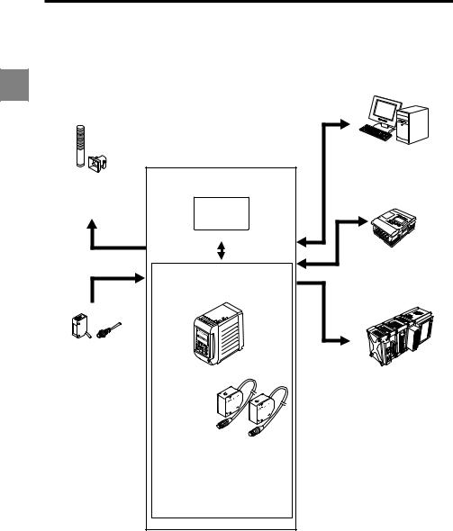
System Configuration
The LK-G Series can be used for various purposes in combination with commercially available 1 devices.
LK-G Series
Indicator light/Buzzer
Issues an alarm depending on the comparator result output.
LK Navigator
Photoelectric/Proximity sensor Transmits a signal to the TIMING input when the target is detected.
Setup support software (LK-H1W) *2 USB/RS-232C
Controller *1
LK-G3001V/LK-G3001PV
LK-G3001/LK-G3001P
Head (two heads max.)
LK-G15/LK-G10
LK-G35/LK-G30
LK-G85/LK-G80
LK-G155/LK-G150
LK-G405/LK-G400
LK-G505/LK-G500
PC
Enables control and acquisition of the measurement value from the RS-232C or the parallel I/O board.
Programmable controller Enables timing control of the measurement and the switching of program No. as well as the control output and the measurement value acquisition.
Recorder
Records the measurement result.
*1: The controller (LK-G3001V/LK-G3001PV) can be separated into the display panel and the controller main unit. You can also purchase them separately.
*2: For the details of the setup support software (LK-H1W) "LK-Navigator", refer to "LK-Navigator User’s Manual" (The PDF file stored in the CD-ROM).
1-2 |
LK-G-M-NO1-E |
1 Before Use
Checking the Package Contents
The LK-G Series consists of the following models. Check if the parts and equipment listed |
1 |
|||
below are included in the package of the model you purchased before using the unit. |
||||
|
||||
|
|
|
|
|
|
|
|||
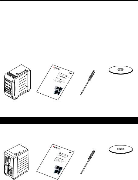
|
LK-G3001V/LK-G3001PV (Single Unit Type Controller) |
|
|
|
|
|
|
|
|
Controller |
User’s Manual |
Screwdriver |
Packed separately |
LK-G3001V/ |
(this manual): 1 |
: 1 |
LK-H1W (CD-ROM) |
LK-G3001PV: 1 |
|
|
|
• Setup support software "LK-Navigator"
• Setup support software User’s Manual (PDF file)
USB cable (3m)
LK-G3001/LK-G3001P (Separate Type Controller)
Controller |
User’s Manual |
Screwdriver |
Packed separately |
LK-G3001/ |
(this manual): 1 |
|
LK-H1W (CD-ROM) |
LK-G3001P/: 1 |
|
|
|
• Setup support software "LK-Navigator"
• Setup support software User’s Manual (PDF file)
USB cable (3m)
LK-G-M-NO1-E |
1-3 |
1 Before Use
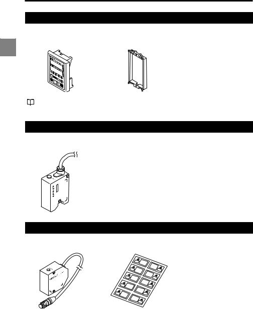
LK-GD500 (Separate Type Controller)
Display panel |
Panel attachment ring |
LK-GD500: 1 |
: 1 |
1 |
|
The communication cable between the controller and the separate type display panel is sold separately. Refer to page A-6 for details.
Head (LK-G15/LK-G10)
Head: 1
LK-G10
Head (Model other than LK-G15/LK-G10)
Head: 1 |
Laser sticker sheet: 1 |
1-4 |
LK-G-M-NO1-E |
|
|
1 Before Use |
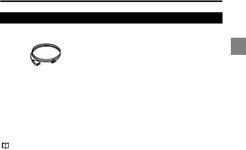
LK-GC2/GC5/GC10/GC20/GC30 |
|
|
Head-to-controller cable: 1 |
|
|
LK-GC2 |
: 2-m cable |
1 |
LK-GC5 |
: 5-m cable |
|
LK-GC10 |
: 10-m cable |
|
LK-GC20 |
: 20-m cable |
|
LK-GC30 |
: 30-m cable |
|
*We have thoroughly inspected the package contents before shipment. However, in the event of defective or broken items, contact your nearest KEYENCE office (address listed in the end of this manual).
For the optional products,refer to "List of Optional Products"(page A-6).
LK-G-M-NO1-E |
1-5 |

1 Before Use
Identifying Part Names and Functions
This section describes the name and function of each part.
1
Controller
Display panel
1Display panel fixing case
2Display panel fixing screw
3Measurement value indicators
Display the measurement value, tolerance comparator value, and various statistical results. The setting items are displayed during setting.
Green: Within the tolerance Red: Outside the tolerance
4Comparator output indicator
Lights during the comparator output (HI, GO, or LO).
5Timing input indicator
Lights when the timing signal is being input.
6Head status display indicator
Displays the laser emission status and the measurement status.
LASER ON |
Laser emission LED. Lights while |
|
the LK-G Series is in operation. |
|
|
STABILITY |
Lights in green or orange within the |
|
measurement range. Lights in red outside |
|
the measurement range, alarm, or laser-off. |
|
|
BRIGHT |
Lights at the exceeding light intensity alarm. |
|
|
DARK |
Lights at the light intensity shortage alarm. |
|
|
7 Operation keys
1 |
4 |
|
5 |
3 |
|
6
7
2
Displays and descriptions of the measurement value indication
Display |
Description |
Numerical value (±999999) |
Displays the measurement result in numerical value. |
|
The display unit, decimal point position, and minimum |
|
display unit vary depending on the settings. |
|
|
FFFFFF (HI output: ON. Monitor output: + 10.8 V) |
Displayed when the value exceeds the display range. |
|
|
–FFFFFF (LO output: ON. Monitor output: –10.8 V) |
Displayed when the value drops below the display range. |
|
|
- - - - - - |
Displayed during the comparator standby state. |
(HI, GO and LO outputs: OFF. Monitor output: –10.8 V) |
|
|
|
1-6 |
LK-G-M-NO1-E |
1 Before Use
Operation keys
Key |
Function |
|
|
|
• During measurement it calls the Program switch mode. |
1 |
|
|
|
|
|
|
• During measurement it calls the Tolerance setting mode.
• When pressed for one second, it calls the Operation setting mode.
•During setting it cancels the setting content and returns to the previous setting.
•During measurement it calls the Statistics display mode.
•During setting it determines the content.
•During measurement it sets the measurement value to zero.
• When pressed for three seconds it cancels auto-zero.
•When pressed for three seconds while inputting the value, it initializes the selected item.
•During setting it switches the display to the next setting item.
• While inputting the value it shifts one digit right.
•When pressed for one second or more it shifts in higher speed.
•During measurement it changes the display for OUT1, OUT2 or both at the same time.
• During setting it switches the setting content.
•While inputting the value it switches symbols or sets numerical values.
•When pressed for one second or more it shifts in higher speed.
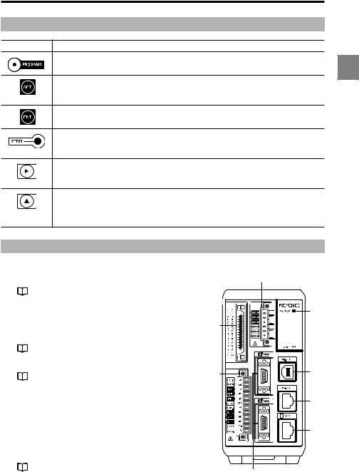
Terminal panel
1RS-232C connector
Establishes communication with a PC or a PLC.
Refer to "Pin Layout" (page 5-2).
2USB connector
Used when connecting the PC via USB.
Refer to "LK-Navigator User’s Manual" for details.
36-pin terminal block
Refer to "6-pin I/O terminal block" (page 4-4).
4 Expansion connector
Refer to "Expansion connector" (page 4-5).
5Head connectors
6Laser emission LED.
Lights while the LK-G series operates.
7Display panel connector
Connects the communication cable between the display panel and the controller.
812-pin terminal block
Refer to "12-pin I/O terminal block" (page 4-2).
3
6
4
8 |
2 |
|
|
|
1 |
|
7 |
5
LK-G-M-NO1-E |
1-7 |
1 Before Use
|
Head |
|
|
1 |
Sensor (emitter) |
6 |
|
1 |
Emits the laser beam for measurement. It |
||
5 |
|||
is protected with a glass cover. |
|||
|
|
||
2 |
Sensor (receiver) |
4 |
|
|
|
Receives the laser beam for measurement. It is protected with a glass window.
3 Attachment holes for the ND filter
|
Used for attaching the ND filter (LK-F1/ |
|
|
LK-F2). |
|
4 |
Installation holes |
|
5 |
Connecting cable |
|
|
Connected to the head-to-controller |
|
|
cable. |
|
6 |
Laser radiation emmission LED |
|
|
Lights or flashes while the LK-G Series is |
|
|
in operation. |
6 |
2
1
5
Status |
LED |
|
Center of the |
Lights in green |
|
measurement range |
||
|
||
|
|
|
Within the |
Lights in orange |
|
measurement range |
||
|
||
|
|
|
Outside the |
|
|
measurement range |
Flashes in |
|
Alarm |
orange |
|
Laser off |
|
|
|
|
4 |
3
1
2
5
6
4 |
3 1
2
1-8 |
LK-G-M-NO1-E |
1 Before Use
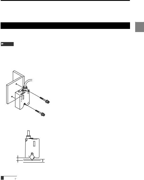
Installing and Connecting the Heads and Optional Parts
Installing the Head |
1 |
|
Adjust the distance between the head and the measuring target, and fix the head with the screws at the two installation holes.
Note
Insulated mounting is recommended when using the head under the positive grounding environment.
■LK-G15/LK-G10
•Installation procedure
LK-G10
M4r35 mm or more
The measurement range is shown in the figure below.
|
G10-LK |
|
Reference |
|
|
distance |
|
|
10 mm |
+1mm |
|
Reference |
||
distance |
Measurement range |
|
0 mm |
–1 mm |
|
(–0.37mm) |
||
|
* The value inside the parentheses ( ) is when the sampling rate is 20 µs.
Reference
The laser emission LED at both diffuse reflection and specular reflection lights in green within ±0.05 mm of the reference position, and lights in orange in the other positions in the measurement range.
LK-G-M-NO1-E |
1-9 |
1 Before Use
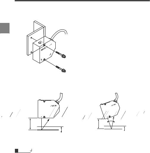
■LK-G35/LK-G30/LK-G37/LK-G32
•Installation procedure
1
M4r35 mm or more
The measurement range is shown in the figure below.
• Diffuse reflection setup |
• Specular reflection setup |
Reference |
|
|
|
|
distance |
|
Reference |
40° |
|
30 mm |
|
|||
|
distance |
|
||
|
|
|
||
Reference |
+5mm |
23.5 mm |
|
|
Measurement range |
|
+4.5mm |
||
distance |
Reference |
|||
0 mm |
–5 mm |
Measurement range |
||
(–1.8 mm) |
distance |
|||
|
–4.5mm |
0 mm |
(–1.6 mm) |
|
* The value inside the parentheses ( ) is when the sampling rate is 20 µs.
Reference
•The laser emission LED at both diffuse reflection and specular reflection lights in green within ±0.25 mm of the reference position, and lights in orange in the other positions in the measurement range.
1-10 |
LK-G-M-NO1-E |
Loading...