


Ultra High-Speed/High-Accuracy
Laser Displacement Sensor
SETUPGUIDE
LK-G5000
INDEX
This guide explains basic setting methods for the LK-G5000. For more detailed information, refer to the User’s Manual.
1Introduction
•Core component layout
•Mounting the Sensor Head
2Setup using LK-Navigator 2 (LK-H2)
•What is LK-Navigator 2?
•Launching LK-Navigator 2
•Sending settings
•Receiving settings
•Displaying measurement values
3Sensor head-related settings
•Head settings
•Measurement mode
•Mounting mode
4OUT settings
P. 2
P. 2
P. 4
P. 4
P. 5
P. 5
P. 5
P. 6
P. 6
P. 7
|
• OUT settings |
P. 8 |
|
• Calculation method |
P. 8 |
|
|
|
|
• Measurement/Tolerance-Measurement type |
P. 9 |
|
|
|
|
• Measurement/Tolerance-Filter |
P. 9 |
|
|
|
|
• Measurement/Tolerance - Tolerance Evaluation |
P. 9 |
|
|
|
5 |
Measurement setup examples |
|
|
• Eccentricity/Vibration Measurement Setting Methods |
P. 10 |
|
|
|
|
• Thickness Measurement Setting Methods |
P. 12 |
|
|
|
|
• Setting methods for measuring the thickness of transparent objects |
P. 15 |
|
|
|
|
• Data storage function setting methods |
P. 17 |
|
|
|
6 |
FAQ's |
|
|
• Common questions |
P. 20 |
|
|
|
|
• Connecting a PC/PLC link unit |
P. 21 |
|
|
|
|
• Wiring guide |
P. 22 |
|
|
|
|
• Optional parts |
P. 23 |
|
|
|
1 
 Introduction
This section contains information related to the component layout and installation of this device.
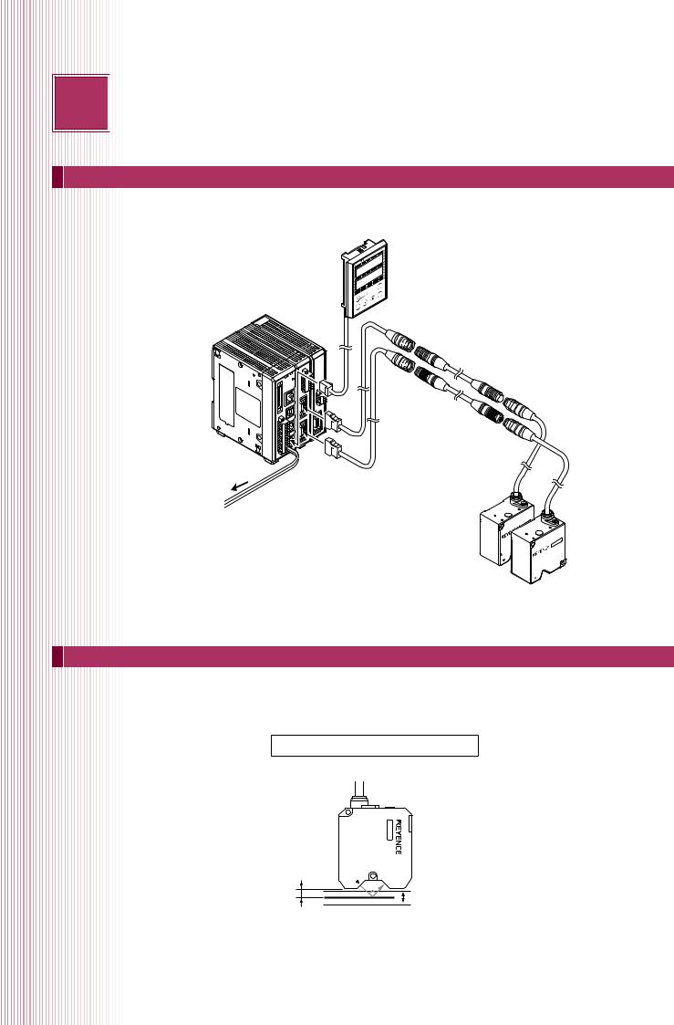
Core Component Layout
Display panel cable (0.33 m/3 m/10 m)
|
|
GO |
|
LK-HD500 |
Display panel |
|
|
|
TIM |
||
|
|
|
LO |
|
|
|
HI |
|
|
|
(When using a separate controller) |
OUT1 |
|
GO |
LO |
TIM |
|
|
HI |
|
|
DARK |
|
OUT2 |
|
|
|
|
|
|
|
BRIGHT |
DARK |
|
|
|
|
STABILITY BRIGHT |
|
|
|
|
ON |
STABILITY |
ZERO |
|
|
|
LASERON |
|
|
|
|
HEAD1 |
LASER |
|
|
|
|
HEAD2 |
PROGRAM |
|
|
ENT |
|
|
|
|
|
|
|
SET |
|
|
|
|
|
Sensor head-to-controller extension cable optional
-HA100 LK POWER
STABILITY
BRIGHT
DARK
1
Sensor head-to-controller cable (0.7 m/2 m/5 m/10 m/20 m/30 m)
24 VDC power supply
Head 02
Head 01
Mounting the Sensor Head
In order to accurately measure a target, mount the sensor head so that the top surface of the target enters the measurement range.
LK-H008
Diffused target/specular reflection target
Reference position |
Measurement range |
|
|
||
8 mm |
+0.5 mm |
|
0 mm |
||
-0.5 mm |
||
|
2

DIFFUSE TARGET
LK-H02x
Reference position
20 mm 
0 mm
LK-H05x
Reference position 50 mm
0 mm
LK-H08x
Reference position 80 mm
0 mm
LK-H15x
Reference position 150 mm
0 mm
Measurement range
+3 mm -3 mm
Measurement range +10 mm
-10 mm
Measurement range
+18 mm
-18 mm
Measurement range +40 mm
-40 mm
SPECULAR TARGET
LK-H02xK
Reference position |
|
|
16.1 mm |
Measurement range |
|
|
||
0 mm |
+2.8 mm |
|
-2.8 mm |
||
|
LK-H05xK
46.3 mm
Reference position
0 mm
LK-H08x+LK-F3
76.7 mm Reference position
0 mm
LK-H15x+LK-F2
147.5 mm Reference position
0 mm
Measurement range +5.2 mm
-5.2 mm
Measurement range +17.6 mm
-17.6 mm
Measurement range +39.5 mm
 -39.5 mm
MEASURING A SPECUL AR TARGET
When measuring specular targets like glass or mirrors, mount the sensor head at an angle so that reflected laser light returns to the receiver. When using the LK-H08x or the LK-H15x, use the LK-F3 or LK-F2 neutral density filter.
3
2 
 Setup using LK-Navigator 2 (LK-H2)
This section will cover basic setup using LK-Navigator 2.
What is LK-Navigator 2?
LK-Navigator 2 is a software package that can be used to set up the LK-G5000 and acquire measurement values.
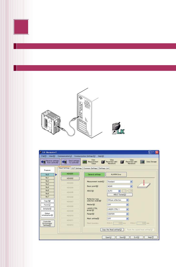
Launching LK-Navigator 2
Connect the sensor head to the controller and turn on the power. Prepare the PC that has had LK-Navigator (LK-H2) installed on it and then connect the controller to the PC via USB cable.
Double click the LK-Navigator 2 icon to launch LK-Navigator 2.
Connecting the PC and the controller
LK-Navigator 2 settings screen
4

Sending settings
Once the button for “Send settings to controller” is clicked, the settings that have been created in LK-Navigator 2 will be applied to the controller.
Receiving settings
Once the button for “Receive settings from controller” is clicked, the controller settings will be downloaded to LK-Navigator 2. This is useful when checking the settings that are currently being used.
Displaying measurement values
Using LK-Navigator 2, it is possible to check the current measurement values. Once the “View Measurement Value” button has been clicked, the Measurement Value Display window will appear.
Once the button for “Measurement value acquisition start” in this window is clicked, it will be possible to check the measurement values.
Once the window is opened, the "Measurement Value Display" screen will be on standby. By clicking the "Measurement value acquisition start” button, it will be possible to acquire measurement values from the controller. By clicking the "Select Display" button, it will be possible to select the OUT number that will be displayed in the Measurement Value Display window.
5

3 
 Sensor head-related settings
This section covers basic head level processing settings.
Head settings
This section controls head level target optimisation processes. This makes it possible to select measurement modes that are optimised for specific target surface conditions and materials, and allows for corrections to compensate for sensor head mounting.
Measurement mode
Selects settings that have been optimised for various target surfaces.
Standard mode
The measurement mode that has been set as default and is optimal for the vast majority of diffuse targets. Measurement is normally performed in this mode.
Translucent object mode
Used when measuring target that scatter light such as translucent resin.
Transparent object mode
Used when performing displacement or thickness measurement for transparent objects like glass or transparent films. Used when the reflectivity of the different surfaces of a transparent object are the same.
6
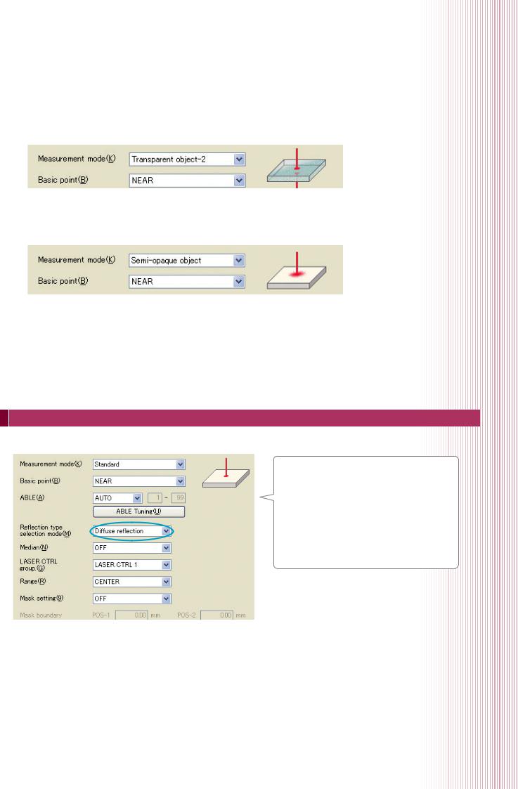
Transparent object 2 mode
Used when measuring transparent object target that have multiple surfaces that differ in reflectivity such as when measuring metal-deposited glass.
Semi-opaque object mode
Used when measuring diffuse targets with strong surface luster.
Mounting mode
Selects settings in response to the mounting method for the sensor head.
“Diffuse reflection”
As listed in P.2 of this guide, this setting is used when the sensor head is mounted perpendicular to the target. “Specular reflection mounting”
A method where the sensor head is mounted at an angle to the target. By performing specular reflection mounting, measurement is possible after correcting physical errors caused by the angle.
7
4 
 OUT settings
These settings related to measurement value processing.
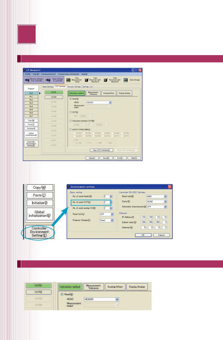
OUT settings
With the LK-G5000, measurement values can be calculated and displayed for each OUT. At default, the number of used OUTs is 2, and up to 12 can be set. The number of used OUTs can be set in the environment settings.
*Once the “No. of used OUT” is changed, all programs will be initialised. The number of used OUTs must be the first thing to be set.
Calculation method
Sets which sensor head will display measurement values to which OUT and performs calculations between these measurement values.
With the settings listed above, measurement values that have been measured with head 01 will be displayed at OUT1.
8
 Loading...