


 Loading...
96M1825
Multipurpose Digital Contact Sensor
GT-70A Series Instruction Manual
Safety Precautions
■ General cautions
•At startup and during operation, be sure to monitor the function performance of the GT-70A Series.
•Do not modify the GT-70A Series or use it in any way other than described in the specifications. The function performance of products used or modified in this way cannot be guaranteed.
•When the GT-70A Series is used in combination with other instruments, function performance may be degraded, depending on operating conditions and the surrounding environment. Use the GT70A Series after fully studying the effect of combined use with other instruments.
•Do not use the GT-70A Series for the purpose of protecting the human body.
•Do not expose the GT-70A Series and peripheral devices to sudden temperature change. This may cause condensation, damaging the equipment.
If the following conditions are encountered, immediately turn OFF the power. Continuing to use the GT-70A Series under these abnormal conditions may cause equipment failure.
WARNING • When water or foreign matter enters the controller
• When the GT-70A Series is dropped or the housing is damaged
• When the GT-70A Series produces smoke or an abnormal smell
• Do not use the GT-70A Series with a voltage other
than specified voltage, as this may cause fire,  WARNING electric shock or equipment failure.
•Do not disassemble or modify the GT-70A Series. This may cause fire or electric shock.
•Be sure to turn OFF the power of the GT-70A Series and any connected devices before connecting or
CAUTION |
disconnecting the cables. Otherwise, there may be a risk |
|
of damage. |
||
|
•Do not turn OFF the power while setting parameters. Otherwise, the settings may be partially or completely lost.
●Environmental conditions
To use the GT-70A Series properly and safely, do not install the GT-70A Series in the following locations. Use of this equipment in an improper environment may cause equipment failure.
•Locations with high humidity, a large amount of dust, or poor ventilation
•Locations where the temperature rises excessively due to direct sunlight, etc.
•Locations near corrosive or flammable gas
•Locations where the GT-70A Series is directly subjected to vibration or impact
•Locations where water, oil or chemicals may come into contact with the GT-70A Series
•Locations where static electricity may easily occur
●Noise countermeasures
Installation near the noise source such as a power source and a power cable may cause malfunction or failure of the equipment. Adopt appropriate countermeasures against noise by using a noise filter or wiring cables in separate ducts, attaching insulation to the amplifier or the sensor head, etc.
●Effects of ambient temperature
Change in ambient temperature may cause detection errors. Keep ambient temperature at a constant level.
It will take about 40 minutes for the internal temperature distribution of the equipment to completely adjust when the ambient temperature has changed by 10°C.
●Warming up
Wait about 30 minutes after the power is turned ON before beginning operation. Immediately after the power is turned ON, the circuit becomes unstable, possibly causing the indicated value to slightly fluctuate.
●Handling of the sensor head
•The GT-70A Series and peripheral devices are precision machines. Do not drop, or cause any other impact to these devices.
•Do not apply weight greater than what is listed below to the spindle part. Do not apply torque in the rotation direction. Otherwise the spindle may break.
•Although the sensor head has a waterproof structure, avoid using in water or in the place where liquid such as water and oil may come into contact with the sensor head.
30 N |
100 N |
1 N |
|
●Extending cable between amplifier and sensor head
Do not cut or extend the cable between the amplifier and the sensor head. This may change the characteristics, causing the specifications not to be satisfied.
●Power supply
•Noise superimposed on the power supply may cause malfunction. Be sure to use the DC stabilized power supply provided with an insulation transformer.
•In the case of a commercially available switching regulator, be sure to ground the frame ground terminal or the ground terminal.
●Effects of vibration
Vibrating the detection target may cause fluctuation in the indicated value. In this case, extend the response time. This ensures more accurate detection values.
●Effects of magnetic fields
Contact by an external magnetic field to the sensor head will influence the output. Avoid installing the GT-70A Series near motors or other equipment and devices that generate strong magnetic fields.
●About dust protective boot
An optional dust protective boot is available (GT-H10: OP-78041, GTH22: OP-78042) for when the included dust protective boot has been cracked or damaged. Please note that we cannot guarantee the protection rating IP67 when the optional part is used. If you need a guarantee for the protection rating IP67, replace the sensor head itself.
1 |
GT-M-E |
CE Mark
The GT-70A Series conforms to CE regulations in Europe. The applicable regulations (EMC directive) are as follows.
EMI EN61326, classA
EMS EN61326
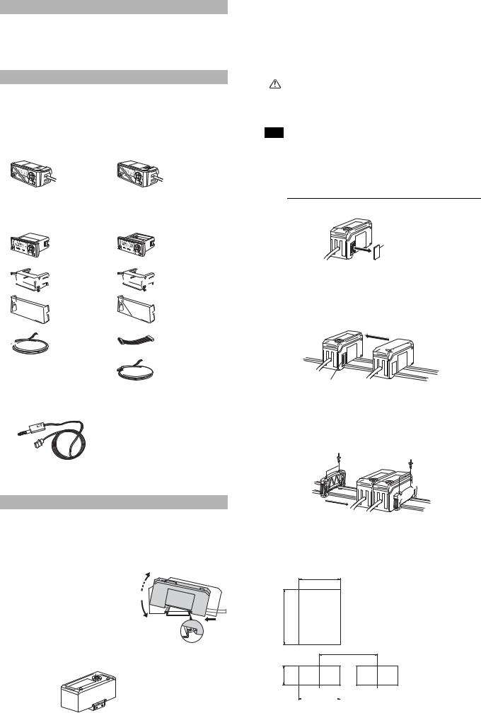
Package Contents
The product package of each model should include the following items. Check that all items are included before use.
■ Amplifier parts
● DIN rail mounting type
GT-71A/GT-71AP (Main unit) |
GT-72A/GT-72AP (Expansion unit) |
||||||||||||||
HI |
P-H |
B-H |
P-P |
|
|
|
|
HI |
P-H |
B-H |
P-P |
|
|
|
|
GO |
|
|
C |
ALC |
|
|
GO |
|
|
C |
ALC |
|
|
||
LO |
|
|
|
|
|
|
LO |
|
|
|
|
|
|
||
SET |
1 |
|
|
|
|
|
|
SET |
1 |
|
|
|
|
|
|
|
23 |
|
|
|
|
|
|
|
23 |
|
|
|
|
|
|
|
TIM |
|
|
|
|
|
SET |
|
TIM |
|
|
|
|
SET |
|
|
|
HI |
|
|
PV |
|
|
|
HI |
|
|
PV |
|
||
|
|
|
|
LO |
|
|
|
|
|
|
LO |
|
|
||
|
|
|
|
|
|
SERIES |
MODE |
|
|
|
|
|
|
SERIES |
MODE |
|
|
|
|
|
|
|
|
|
|
|
|
|
|
||
Amplifier x 1 Instruction manual x 1 |
Amplifier x 1 |
||||||||||||||
● Panel mounting type |
|
|
|
|
|
|
|
|
|||||||
GT-75A/GT-75AP (Main unit) |
GT-76A/GT-76AP (Expansion unit) |
||||||||||||||
GOHI |
P-H |
B-H |
P-P |
CALC |
|
Amplifier x 1 |
GOHI |
P-H |
B-H |
P-P |
CALC |
|
|
Amplifier x 1 |
|
LO |
|
|
|
|
|
|
LO |
|
|
|
|
|
|
||
|
TIM |
HI |
|
|
|
|
|
TIM |
HI |
|
|
|
|
||
|
|
LO |
RV |
|
|
|
|
|
LO |
RV |
|
|
|||
|
|
|
|
|
|
|
|
|
|
|
|
|
|||


 Panel mounting bracket x 1


 Front protective cover x 1

 Power cable (2 m) x 1
  (Number of conductors: 8)
Instruction manual x 1


 Panel mounting bracket x 1


 Front protective cover x 1
Expansion cable (50 mm) x 1

 Power cable (2 m) x 1 (Number of conductors: 6)
■ Sensor head parts
GT-H10/GT-H22 GT-H10L/GT-H22L
Sensor head x 1
Handling instruction x 1
We have taken all possible precautions in packaging; however, if any parts are found to be defective or broken, please contact your nearest KEYENCE sales office.
Mounting the Amplifier and Wiring
■ Mounting the amplifier
●DIN rail mounting type (Main unit)
This section describes how to mount the DIN rail mounting type: GT71A/71AP (Main unit).
1 Fit the tab of the lower part of the main unit to the DIN rail. While inserting the main unit in the direction of Arrow (1), push the body down in the direction of Arrow (2).
2 To detach the amplifier, while pushing the main unit in the direction of Arrow (1), pull the body up in the direction of Arrow (3).
(3)
(1)
(2)
When using a fixture (OP-76877), mount as shown below.
 Fixture: OP-76877
GT-M-E |
2 |
●DIN rail mounting type (Expansion unit)
This section describes how to mount the DIN rail mounting type: GT72A/72AP (Expansion unit).
The expansion unit can only be used in addition to the main unit. Up to nine expansion units can be added to one main unit.
|
|
• When adding an amplifier (expansion unit), be |
|
|
sure the power of both main and expansion |
CAUTION |
units is OFF before operation. Mounting when |
|
the power is ON may damage the equipment. |
||
|
|
• Be sure to completely contact an expansion unit |
|
|
to a main unit. Oblique or improper connections |
|
|
may damage the equipment. |
|
|
|
|
|
|
Note • When adding an expansion unit(s), be sure to use a 24 VDC power supply.
• An expansion unit of different output type cannot be added (for example, an expansion unit of NPN output cannot be added to a main unit of PNP output).
• An expansion unit of the DIN rail mounting type cannot be added to a main unit of the panel mounting type.
1 Detach the expansion cover of the main unit.
Main unit 
Expansion cover
2 Mount the expansion unit to be added to the DIN rail.
Refer to page 2, "DIN rail mounting type (Main unit)", for details about how to mount.
3 Push and fix the expansion unit to the connector of the main unit until it clicks.
Main unit


 Expansion unit
Connector
4 Mount the end units (OP-26751: a set of two pieces) on both sides of the amplifiers (the main unit and the expansion unit), then fix the end units with screws on the upper part of each end unit (2 points x 2 units).
The mounting method of the end unit is the same as that of the amplifier.
End unit 

 End unit
●Panel mounting type (Main unit)
This section describes how to mount the panel mounting type: GT- 75A/GT-75AP (Main unit).
1 Create a panel opening for mounting referring to the dimensions below.
45
(unit: mm)
X=24 x (Number of amplifier unit -1)+21
X
63 min.
+0.4 21 -0
45 |
|
Panel cut dimension |
2 Insert the main unit, back end first, into the opening of the panel.

3 Insert the panel mounting bracket in the direction shown below into the main unit from the back, then fit the front protective cover to the main unit face.
Front protective cover
Amplifier
Panel
Panel mounting bracket
To detach the panel mounting bracket, pull it while pushing apart the tabs provided on its both ends.
Tab
●I/O cable
The following illustrates the I/O power cable (also applicable to the panel mounting type).
Refer to page 10 of this manual for details about I/O circuits.
Brown *1
Blue *1 |
|
12-24 VDC |
Black
HIGH output
White
LOW output
Gray
GO output
Pink
PRESET input
Violet
BANK A, or RESET input *2
Pink/Violet
BANK B, or TIMING input *3
*1 Expansion units (GT-72A/72AP/76A/76AP) do not include brown and blue cables. Power supply is 24 VDC when an expansion unit(s) is added.
*2 Default: BANK A input
*3 Default: TIMING input
●Panel mounting type (Expansion unit)
This section describes how to mount the panel mounting type: GT76A/76AP (Expansion unit).
The expansion unit can only be used in addition to the main unit. Up to nine expansion units can be added to one main unit.
Connecting and Mounting the Sensor Head
■ Names of parts of the sensor head
•Turn OFF the power before connecting the expansion cable. Inserting or pulling the cable when the power is turned ON may damage the
CAUTION |
equipment. |
|
• Be sure to completely connect the expansion |
|
cable. Oblique or improper connections may |
|
damage the equipment. |
Indicator |
|
Dust protective boot |
Connection |
|
plug |
Spindle |
|
|
Dust protective boot* |
Note |
• |
When adding an expansion unit(s), be sure to use a |
|
Contact point |
Contact point |
|
|
24 VDC power supply. |
|
* Not included in the GT-H10L and GT-H22L. |
|
|
• |
An expansion unit of different output type cannot be |
■ |
Connecting the sensor head |
|
|
|
added (for example, an expansion unit of NPN output |
|||
|
|
|
|
|
|
cannot be added to a main unit of PNP output). |
● DIN rail mounting type |
•An expansion unit of the panel mounting type cannot
be added to a main unit of the DIN rail mounting type. 1 Switch the connection plug of the sensor head to "unlocked",
1 Create panel openings for mounting according to the number of expansion units to be mounted (the expansion unit to be added).
Refer to page 2, "Panel mounting type (Main unit)", for details about panel cut dimensions.
2 Mount the amplifier (the expansion unit to be added) to the panel.
Refer to page 2, "Panel mounting type (Main unit)", for details about how to mount.
3 Connect the amplifiers (the main unit and the expansion unit) with an expansion cable.
Expansion cable
then insert it into the connector on the side face of the amplifier.
Unlocked
2 Turn the round end of the connection plug clockwise until it clicks to switch to "locked".
click
Locked
•To detach the connection plug of the sensor head, follow the above procedures in the opposite order.
■ Wiring of amplifier
●How to connect the power cable to the panel mounting type
The accessory power cable (I/O cable) must be connected to the amplifier of the panel mounting type.
click |
|
Power cable |
|
(When connecting the power cable) |
(When disconnecting the power cable) |
Note • The number of power cable conductors is different between the main unit and the expansion unit (Main unit: 8 conductors, Expansion unit: 6 conductors).
•The power of the expansion unit is supplied through the expansion cable being connected to the main unit. If the I/O line of the expansion unit is not used, cut the cable at the edge of the connector.
● Panel mounting type
1 Switch the connection plug of the sensor head to "unlocked", then insert it into the connector on the back face of the amplifier.
Unlocked
2 Turn the round end of the connection plug clockwise until it clicks to switch to "locked".
click Locked
•To detach the connection plug of the sensor head, follow the above procedures in the opposite order.
3 |
GT-M-E |
Loading...